Note: Descriptions are shown in the official language in which they were submitted.
CA 02275338 2003-10-31
AERIAL CABLEWAY LEADING TO AN AEROSTATIC AIRBORNE BODY
TECI;NICAL FIELD
The invention relates to a system for transporting
passengers and goods on a cableway between the ground and
an aerostatic buoyancy body.
BACKGROUND OF TFiE INVENTION
Similar transport channels, though only for
transporting goods, are known e.g. from SU 18 087 65 A1
and in a somewhat extended sense also from SU 58 60 22.
Passenger and goods cableways are also known per se.
In the case of the cableways known from the
citations, the main purpose is to transport heavy goods
such as tree-trunks, building material or the like
substantially horizontally in areas where no runways,
railways or similar structures can or may be constructed.
The solutions found may therefore be adequate to solve
the problems posed. In the known devices the aerostatic
buoyancy body also serves as a support or a suspension
tower but not as a cableway station.
Cableway construction between two stationary sites
for transport of passengers and goods is a highly-
developed branch .of the art. In the art of captive
aerostats for monitoring space by electronic means, there
are known structures and devices for anchoring, lowering
and drawing in captive balloons of the kind in question,
e.g. in the pamphlet "71 M.TM. Aerostat" published by
Messrs TCOM, L.P., Columbia, Md., USA.
However, when constructing a cableway to an
aerostatic buoyancy body, problems occur which cannot be
- 1 -
CA 02275338 2003-10-31
solved by transferring known solutions from the sector of
terrestrial cableway construction to the special features
of the art of captive balloons. The term "captive
balloon" here and hereinafter will basically stand for an
aerostatic buoyancy body which is anchored to ground by a
line and can also comprise components of an aerodynamic
buoyancy means.
The problem in the present case is to construct a
cableway between the ground and a captive balloon so as
to allow for the limited carrying capacity of aerostats
and for all the relevant safety aspects. Another aim is
to transport groups of passengers quickly and provide
them with a safe stopping place on a platform carried by
a captive balloon.
SU1~1ARY OF THE INVENTION
As embodied and broadly described herein, the
present invention provides an aerostatic buoyancy body in
the form of a captive balloon, such as a tethered
dirigible or blimp, that has a gondola suspended directly
underneath it for housing people and goods. The
aerostatic buoyancy body is moored with a cable to a
rotatable ground station, which rotates to control the
orientation of the aerostatic buoyancy body and which
controls the altitude of the aerostatic buoyancy body by
reeling the mooring cable in or out . One or more cabins
ride on cableways in order to shuttle passengers and
goods back and forth from the ground station to the
aerostatic buoyancy body. The system may also have more
than one aerostatic buoyancy body or redundant mooring
cables.
- 2 -
CA 02275338 2003-10-31
The mooring cable, which is wound on and off a drum,
has a core which contains lines for conveying energy and
exchanging information between the ground station and the
gondola and is surrounded by a jacket of high-strength
plastics material fibres and earth wires.
The transport system includes at least two
additional transport cables usually movable in opposite
directions extending between the ground station and the
gondola and at least one cabin is fastened to each cable.
A substantially horizontal frame is suspended on
ropes from the aerostatic buoyancy body and bears a shaft
which is disposed so as to be movable at right angles to
the direction in which it extends and in turn supports
the gondola on suspension components. The transport
cables in the gondola are received by a drive device
which, together with the means fastening the mooring
cable are fastened to the shaft so that the tensile
forces exerted by them can be received without torque by
the shaft.
The transport system further has components for
moving the shaft parallel to its original position so
that the line of action of the tensile forces exerted by
the at least three cables always extends through the
centre of buoyancy of the aerostatic buoyancy body.
The gondola includes a computer for monitoring and
controlling all mechanical processes. The ground station
also has a computer for monitoring and controlling all
mechanical processes and is linked for data transfer
purposes to the computer in the gondola. The ground
station also includes means for anchoring the aerostatic
CA 02275338 2003-10-31
buoyancy body and means for continually rotating the
anchored aerostatic buoyancy body to windward.
Both the gondola and the cabins have life-saving
means which, in the event of a loss of buoyancy by the
aerostatic buoyancy body and/or a breakage of one of the
cables, ensure a safe return to the ground.
BRIEF DESCRIPTION OF THE DRAWINGS
The invention will be explained in further detail
with reference to the accompanying drawings, in which:
FIG. 1 is a diagrammatic general view of a first
exemplified embodiment;
FIG. 2 is a slanting top view of the ground station;
FIG. 3 is a side view of the captive balloon
anchored in the ground station;
FIG. 4 is a plan view of FIG. 3;
FIG. 5 is a side view of the balloon gondola;
FIG. 6 is a plan view of the gondola;
FIG. 7 is a slanting top view of the captive
balloon;
FIG. 8a is a side view of a cabin, partly in
section;
FIG. 8b is a plan view of a cabin;
FIG. Sc is a front view of a cabin;
FIG. 9 is a perspective view of a cabin with
extended life-saving devices;
FIG. 10 shows a detail of the cable guidance;
FIG. 11 is a perspective view of an additional
embodiment of a gondola; and
FIG. 12 shows a detail of the suspension device.
- 4 -
CA 02275338 2003-10-31
DETAILED DESCRIPTION OF THE PREFERRED E1~ODIMENT
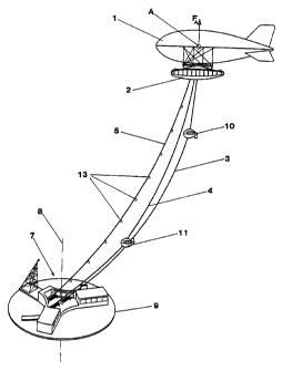
FIG. 1 is a very simplified view of a cableway
according to the invention in a first embodiment. A
captive balloon 1 carries a gondola 2 to which three
cables are attached, two transport cables 3, 4 and a
mooring cable 5. The two transport cables 3, 4 end at a
ground station 7 which is rotatable around a vertical
axis 8 and can rotate on a circular rail 9. Each
transport cable 3, 4 bears a cabin 10, 11 for carrying
passengers. Although details are referred to in
subsequent drawings, the basic features can be explained
with reference to FIG. 1. The transport cables 3, 4, both
in the gondola 2 and in the ground station, run on and
off drums.
The ground station 7, which will be described in
further detail with reference to FIG. 2, can be actively
tracked with reference to the prevailing wind direction
or the site of the captive balloon 1, with the result
that the ground station 7 is always to windward of the
captive balloon 1 and the cables 3, 4, 5 extend to
leeward.
The mooring cable 5 is secured to the gondola 2 at a
suitable place and runs on a drum 19 in the ground
station 7. The captive balloon 1 can therefore be
released to any desired height, whereas the unused length
of the transport cables 3, 4 remains on drums 17, 18 in
the ground station 7.
Basically, the cabins 10, 11 are coupled in shuttle
operation, driven by the traction motors provided in the
gondola 2. For safety reasons, however, the coupling can
be disconnected, so that the two cabins 10, 11 can move
- 5 -
CA 02275338 2003-10-31
downwards separately. In the ground station 7 the
transport cables 3, 4 are wound up at the same speed as
they are unwound in the gondola 2 and vice versa; however
the motors driving the cable drums in the ground station
7 are used only for slowing down the cables 3, 9 when
paid out and for compensating the length of the cables
when drawn in, whereas the actual traction motors are in
the gondola 2 as already described. The mooring cable 5,
like the transport cables 3, 9, is preferably made of
aramid fibres or synthetic fibres of similar quality. It
has an "umbilical" construction, wherein the core of the
mooring cable 5 contains lines for conveying energy and
for transmitting information between the gondola 2 and
the ground station 7, surrounded by a jacket made of the
said materials and receiving the tensile forces, and
suitable electric earth wires.
In an advantageous embodiment the captive balloon 1
has photovoltaic cells 45, so that the plant, even at
night, can be operated with neutral energy. In addition
to the individual conventional captive balloon 1 shown in
FIG. 1, embodiments with two or three such captive
balloons are included in the inventive idea, or
embodiments comprising different shapes of balloon or a
number of balloons. Likewise the invention includes
buoyancy bodys with dynamic buoyancy in addition to
aerostatic members.
The invention also includes equipping the mooring
cable 5 with beacons 13 which are illuminated at least at
night and comprise passive reflectors or transponders for
radar signals, to meet the requirements of safety in
flight and reliability of the balloon cableway.
- 6 -
CA 02275338 2003-10-31
FIG. 2 is a detailed representation of the ground
station 7. A circular, single or double rail 9 is e.g.
surrounded by an annular road 14 giving access to two
waiting rooms 15, 16. The waiting rooms 15, 16 are entry
and exit bays for cabins 10, 11 respectively. In the
present case, cabin 10 is on the ground. The drawing also
shows the three cable drums 17, 18, 19, one for each
cable 3, 4, 5. It does not show motors, transmissions and
other known equipment, for operating the cable drums 17,
18, 19 or for rotating the entire ground station. The
axis 8 extends approximately through the middle of the
arrangement of the three cable drums 17, 18, 19. A tower
with a device 21 for receiving the captive balloon 1
is disposed at the windward end of the ground station 7.
15 The diameter of the rail 9 is about equal to the length
of the captive balloon 1, so that when moored, the
balloon does not take up more space than the entire
installation in the operating state.
The positioning of the cable drum 17, 18, 19 towards .
20 the middle of the ground station 7, with each waiting
room 15, 16 at the periphery, is not per se essential to
the invention. Alternatively the cable drums 17, 18 can
be on the periphery and the two waiting rooms 15, 16 can
be at the centre or if necessary combined in a single
group.
The ground station 7 also contains control rooms 22
for machinery and administration.
The ground station is actively tracked by
determining the position of the gondola 2 and forming the
difference from the position of the ground station 7. The
position can be determined either via an inertial
_ 7 _
CA 02275338 2003-10-31
platform or GPS location on the gondola 2. Data are
transmitted by the data line in the captive part 5 or by
radio, and the same applies to synchronisation of the
cable speeds in the gondola 2 and the ground station 7.
These and other tasks are performed by a computer (not
shown) in the control rooms 22, exchanging data with a
computer (likewise not shown) in the gondola 2.
FIG. 3 shows the captive balloon 1 and gondola 2, as
described in FIG. 5, moored to the tower 20. As before,
the vertical forces due to buoyancy are taken by the
mooring cable 5. Horizontal forces due to wind are taken
by the tower 20, provided the nose of the captive balloon
1 is exactly to windward. Since the position of a moored
captive balloon substantially coincides with the position
of the ground station 7, the said difference formation
between positions is not suitable in this case for
tracking the ground station 7.
For this purpose, the following components are
provided: The entire ground station 7, which can rotate
around the axis 8 when the cableway is in operation, is
made pivotable around an axis 25 extending through the
tower 20. All the engineering equipment of the ground
station 7, such as waiting rooms 15, 16, cable drums 17,
18, 19 and control rooms 22, rotates on an additional
rail 26 in the form of a circular sector. The radius of
the rail depends on the weight and the centre of gravity
of the ground station 7 and is approximately equal to the
radius of the circular first rail 9. FIG. 4 shows the
ground plan thereof.
If the captive balloon 1 is moored and in a side
wind, the entire ground station 7, under the influence of
_ g _
CA 02275338 2003-10-31
the wind forces, preferably rotates around the axis 25 on
the second rail 26. This motion is detected by sensors in
the region of the ground station 7 and is processed by
the computer in the control rooms 22, which actuates the
motors for rotating the entire ground station 7 on the
first rail 9 until the captive balloon 1 is again moored
in the ground station 7 in a symmetrical position and
subject to symmetrical forces. The said sensors, based on
ultrasound, infrared or measurement of force, are known
and installation thereof is prior art. Consequently
neither sensors or motors are shown. The procedure
described avoids large lateral wind forces and also
ensures that the ground station 7 has to be tracked only
occasionally, i.e. when the captive balloon 1 goes
outside a defined limiting position.
One embodiment (not illustrated) of the ground
station 7 is in the form of a moored floating member. If
the floating member is moored by a chain or rope to the
bottom of the water, there will be no need for pivoting
or tracking devices. The captive balloon 1 and the ground
station 7 will then swing round the point of anchorage to
the bottom of the water. Of course, the floating member
can be a seaworthy ship and if required can be actively
guided in accordance with the direction of the prevailing
wind.
No especial mention is made of the devices and
precautions generally known in the art of cableways.
FIG. 5 shows the gondola 2. It is suspended from a
continuous shaft 32 via four suspension components 31
(only two of which are visible). A11 the drive devices
and securing means for the captive cable 5, shown in
_ g _
CA 02275338 2003-10-31
simplified form, are contained in a casing 33, so that
the tensile forces originating from the cables 3, 4, 5
can be received without torque by the shaft 32. The
shaft, together with the casing 33, is movable on
horizontal rails 34 e.g, by hydraulic means, and
accordingly a hydraulic cylinder 35 is shown. The rail 34
and the casing 33 are supported by a frame 36 secured by
ropes 37 to the captive balloon 1, as also shown in FIG.
6. The shaft 32 can be moved so as to guide the line of
action (marked 41 in FIG. 3) of the cable forces through
the centre of buoyancy of the captive balloon, so that
positive or negative restoring moments on the captive
balloon can be immediately compensated under computer
control. To this end the frame 36 is equipped with a
diagrammatically indicated clinometer 38. The gondola 2,
which is suspended from and swings under the frame 36,
has shock-absorbers 39, which can either be passive in
the form of vibration absorbers or active in the form of
hydraulic cylinders. These can absorb swings of the
gondola 2 or actively keep it horizontal.
In its central region the. gondola 2, which is e.g.
round or oval in cross-section, has openings for the
cables 3, 4, 5 and for the entrance and exit from the
cabins 10, 11. To enable passengers to enter and leave,
the opening under the cabin when retracted (cabin 10 in
FIG. 3) can be closed by a foldable or insertable floor
40.
FIG. 6 is a top view of the frame 36 and gondola 2.
All components in this drawing have already been
introduced and explained with reference to FIG. 5.
- 10 -
CA 02275338 2003-10-31
In an installation according to the invention and
described here, there are risks to the safety of persons
and things. The risks can be classified as follows:
a) The captive balloon 1 loses gas.
b) The captive balloon 1 is completely torn open by
external action.
c) The mooring cable 5 breaks.
d) One of the transport cables 3, 4 breaks
either over cabin 10 or 11,
or under cabin 10 or 11.
These safety risks are eliminated according to the
invention by the following constructions.
a) In view of the large volume of gas, of the order
of 10,000 to 40,000 m3, and an excess pressure in the
range from 500 Pa to 1,000 Pa the loss of buoyancy per
unit time, even in the case of fist-size holes, is so
small that if a loss of gas of this kind is detected the
captive balloon can be hauled in by the normal procedure.
b) In view of the existing technology for captive
balloons, a sudden loss of gas is conceivable only as a
result of deliberate destructive external action. Even in
this case, however, methods are provided for a safe
return of the gondola 2 to ground. In FIGS. 3 and 4, box
like components 42 are mounted on the gondola 2. These
each contain a parachute with a release device. In the
assumed case of a substantial loss of buoyancy forces, as
measured by a dynamometer at the suspension points 43 of
the frame 36, the computer on the gondola 2 will activate
the mechanisms for releasing the parachutes. Depending on
the size and weight of the gondola 2, cabins 10, 11 and
cables 3, 4, 5, four to eight cargo parachutes of
- 11 -
CA 02275338 2003-10-31
standard diameter 100 feet (approx. 30 m) are provided,
enabling the load to descend at a maximum rate of about 7
to 8 m/sec. If, in case b), one of the cabins 10, 11 is
in the gondola 2, it will remain there and glide
therewith to ground on the said parachutes. Suspension,
connection and release of such combined cargo parachutes
is prior art and need not be further explained here.
Also, in the safety system according to the invention,
the gondola 2 suspended from parachutes floats downwards
on cables hauled in from the ground station 7 and remains
to leeward of the ground station, i . a . is hauled against
the wind, which enables the hauling process to be
efficiently controlled. This does not place any special
requirements on the drives of the cable drums 17, 18,
since during normal operation the transport speed of the
cabins 10, 11 is about 10 to 15 m/sec, compared with a
provided rate of descent of the gondola 2 in an emergency
of about 7-8 m/sec as stated. In order to cushion the
impact on the ground, the gondola 2 has a collapsible
zone 49 e.g. in the form of an air bag, diagrammatically
shown in FIG. 3. Honeycomb structures or pneumatic spring
legs are other possible collapsible zones according to
the invention.
c) If the mooring cable 5 breaks the gondola 2 will
still be anchored to the two transport cables 3 and 4,
which are dimensioned to bear the additional stress by
themselves. In this emergency, however, both the energy
and the data connection by wire or glass fibre will fail,
and consequently the following precautions must be taken:
self-sufficiency in energy, as described with
reference to FIG. 7, and
- 12 -
CA 02275338 2003-10-31
a redundant data connection is provided by radio.
Since there is no pressure of time in an emergency
of this kind, the hauling-in process can be interrupted
when one of the cabins 10, 11 enters the ground station
7. Either the cabin can be disconnected from the
corresponding transport cable 3, 4 or the balloon-side
part of the transport cable can be hauled into the
gondola 2.
d) If the balloon-side part of one of the transport
cables 3, 4 breaks, this emergency will be dealt with by
the means described with reference to FIG. 8. If the
break is in that part of a transport cable 3, 4 which
connects the corresponding cabin 10, 11 to the ground
station 7, the cabin 10, 11 can either be pulled into the
gondola 2 or can be left on the ground, depending on
which solution is safer in view of the position of the
cabin 10, 11 in question between the ground and the
captive balloon 1.
FIG. 7 is a perspective view of the captive balloon
1 from above, with some components which have hitherto
not been described or not in detail. On the one hand the
balloon carries a number of photovoltaic cells 45, which
are given an area such that the energy required by the
airborne part of the installation can be covered at least
during the day. If in a sample calculation it is assumed
that
on the ane hand the cabins 10, 11 are in shuttle
operation and are mechanically coupled and under the same
load, so that in this case only the loss by friction
needs to be compensated, amounting to about 10~,
- 13 -
CA 02275338 2003-10-31
if a cabin weighs 800 kg and rises vertically at 15
m/sec, a power of 120 kW is necessary in order to raise a
cabin (without shuttle operation),
consequently the loss through friction is about 12
kW, and
about 10-15 kW are required for lighting, auxiliary
equipment and controls,
a total power of about 30 kW will be appropriate. If
the photovoltaic cells 45 are assumed to have an
efficiency of 10~ (relative to the solar constant), about
300 m3 of solar cells 45 will be necessary. Compared with
the approximately 3,500 mz surface area of a captive
balloon 1, this is only a small part of the total
surface, and can also be increased without difficulty to
obtain a more reliable supply. The captive balloon 1 can
also carry a helicopter landing platform 46, e.g. on a
pneumatic pad 47, closed by a hatch 48. If the captive
balloon 1 is at an excess pressure of e.g. about 750 Pa,
it will withstand a load of 750 N/m3 without buckling, so
that a landing platform measuring about 150 m2 will have a
gross carrying power of about 112 kN. Of course, the
landing weight of a helicopter is limited not only by the
aerostatic load-bearing power of the balloon shell, but
also and at least equally by the net buoyancy of the
captive balloon 1. Furthermore when a helicopter lands
the relative position of the centre of gravity and the
centre of buoyancy are altered, and consequently the
restoring moment of the captive balloon 1 and the gondola
2 is affected. This also limits, the maximum.weight of a
helicopter.
- 14 -
CA 02275338 2003-10-31
FIG. 8 shows an embodiment of the cabin 10; FIG. 8a
is a side view, partly in section, FIG. 8b is a plan
view, partly in section, and FIG. 8c is a front view.
The cabin 10 has an aerodynamic profile, both to
reduce the wind resistance and always to keep the cabin
to windward. The prevailing wind also includes the
relative wind. The wind vector therefore always has an
appreciable vertical component. For improved
stabilisation against the total wind, the cabin 10
10 carries a stabilising fin 65 which can be swung around an
approximately horizontal axis 66. The fin 65 is bent
downwards when the cabin 10 rises and upwards when the
cabin descends, as shown in FIG. 8a.
In the interior the cabin l0 has a conical shaft 59,
the opening angle of which includes all inclinations of
the transport cable 3 which occur in practice. The wall
57 of the shaft 59 is e.g. the load-bearing construction
for the cabin 10, to which all other components are
directly or indirectly fastened. The transport cable runs
through the shaft 59 and is tightly clamped in a sleeve
54 The sleeve, e.g. at its top end, is connected by a
universal suspension 55, supported by a shaft 60. The
universal suspension 55 enables the cabin 10 to swing in
any vertical plane.
Such swinging motion is absorbed by a
diagrammatically-indicated shock-absorber 49. A second
shock-absorber at right angles to the shock-absorber 49
and to the plane of the drawing, is also provided but is
omitted for clarity in the drawings.
The axis 60 is in the vertical line of action of the
centre of gravity S of the cabin 10. The cabin 10 has
- 15 -
CA 02275338 2003-10-31
external windows 52. Over the glazed part, the cabin 10
has a hood 50 which extends over the shaft 59 and has an
opening 62 for the transport cable 3. The hood 50 also
covers a number (three in the present case) of containers
53 holding parachutes, on which the cabin 10 can float
downwards if the transport cable 3 breaks above the cabin
10. A cable break of this kind will be detected e.g. by a
dynamometer along the axis 60. Alternatively the
containers 53 can be disposed underneath the passenger
space.
Underneath the glazed part 52, the cabin has a floor
cap 51 in which a collapsible zone 58, e.g. in the form
of an air bag, is fastened. In addition, four legs 67 for
example can be swung out after being simultaneously
triggered, like the parachutes in the containers 53. Each
leg can have an air bag-like pneumatic shock-absorption
member 68 and can be connected to the other legs e.g. by
a cable 69, as shown in FIG. 9. Also, safety can be
increased and weight can be saved by providing seating
facilities, which additionally absorb the shock of an
emergency descent on parachutes.
The drawings omit obvious features such as
telecommunication equipment, computers, emergency aid
equipment, energy accumulators and the like.
The cabin can be shaped to ensure that even in a
complete calm, the cabin 10 is to windward and does not
begin to rotate around the transport cable. Of course any
twisting of the transport cables 3, 4 is carefully
eliminated before starting.
Any slope of the cabin 10 through an asymmetrical
distribution of weight can be counteracted, at least in
- 16 -
CA 02275338 2003-10-31
the sagittal plane, if either the axis 60 of the
universal suspension 55 is movable or if an electric
energy accumulator, which is provided in any case for
operating the on-board and the safety equipment, can be
moved in the sagittal plane. Of course the two
precautions can be combined to obtain an optimum trimming
device.
In another embodiment of the invention, which is
only partly illustrated by drawings since the main
features of the invention have already been described,
the transport cables 3, 4 in the gondola 2 each run round
a pulley 70, 71 as shown in FIG. 10. The two pulleys 70,
71 are coupled and usually run in opposite directions;
the coupling can be e.g. mechanical, hydraulic or
electric. The coupling means are diagrammatically shown
as a box 72 in FIG. 10 and are known per se. In this
embodiment each transport cable 3, 4 extends from the
ground station 7 to the corresponding pulley 70, 71 and
back to the ground station 7 and is driven by a traction
motor in the ground station 7. The two traction motors
can also be coupled. The means for coupling the cable
motion, both in the gondola 2 and in the ground station
7, can also be used to break the coupling, so that the
two cabins 10, 11 can descend separately.
The invention also includes a third embodiment,
using a number of cabins 80 instead of two single cabins
10, 11. The number is restricted by the carrying power of
a single endless rotating transport cable 81 and by the
buoyancy of the captive balloon 1. The transport cable 81
is therefore technically equivalent to the combined
transport cables 3, 4, though this does not exhaust the
- 17 -
CA 02275338 2003-10-31
process of manufacturing the transport cable 81. FIG. 11
shows one of the cabins 80 and FIG. 12 shows a detail of
the means fastening the cabin 80 to the transport cable
81.
The cabin 80 in FIG. 11 has a substantially
horseshoe-shaped cross-section, aerodynamically modified.
The transport cable 81 runs between the two parts of the
cabin 80 and also completely outside it. Modifications
are also made to the sleeve 54 and the universal
suspension 55, as shown in FIG. 12. The universal
suspension 55 supports the cabin 80 on a holder 82. A
plate 83 fastened to the sleeve 54 has regular-spaced
perforations 84 which are adapted to receive hooks which
can take the weight of the cabin 80 in the gondola 2.
The modified suspension of the cabin 80 comprises
the sleeve 54, which here is longitudinally divided and
provided with a locking means 86. On the side remote from
the observer, the sleeve 54 has e.g. hinge joints, so
that after the lock 86 has been opened the upper part of
the sleeve 54 can be swung open.
The sleeve 54 is mounted on a supporting
construction 87 which carries the plate 83 underneath so
that in the front, in the direction of the cable, it
carries the universal suspension 55 to which the cabin 80
on the holder 82 is fastened.
If the cabin 80 on the cable 81 moves upwards and
reaches the gondola 2, a chain equipped with the said
hooks engage in the perforations 84 in the plate 83.
Initially the chain moves at the same speed as the
transport cable 81. As soon as the hook engages, the lock
_ 18 _
CA 02275338 2003-10-31
86 is released externally and the sleeve 54 is opened,
thus freeing the cabin 80 from the transport cable 81.
The chain is then slowed down, as known in cableway
technology, and the cabin 80 is transferred to a second
cable, rotating slowly and horizontally in the gondola 2.
The second chain slowly conveys the gondola 80 to the
suitably-equipped transfer station on the transport cable
81, which is moving faster. An exit for passengers can
likewise be provided in this embodiment. A number of
cabins 80 can simultaneously be present in the gondola 2.
The transfer of cabin 80 from the transport cable 81
to the plate 83, which is in the gondola, on a transport
system based on a chain or a belt, and is provided with a
hook and perforations 84, is not in itself essential to
the invention. Other solutions will be available to the
cableway engineer. According to the invention, the
sleeves 54 can be opened around the transport cable 81.
At the ground station 7, the cabins 80 are
transferred to a stationary transport system completely
similar to that in the gondola 2. The unused length of
the transport cable 81 in the ground station runs into a
cable storage means, so that the height of ascent is
technically limited only upwards by the length of the
transport cable, as is the case in all other embodiments
described.
The transport cable 81, like the transport cables 3,
4 in FIG. 10, runs round a guide pulley in the gondola 2.
The drive of the transport cable 81 can be either in the
gondola 2 or in the ground station 7.
- 19 -