Note: Descriptions are shown in the official language in which they were submitted.
CA 02276071 2006-01-04
REMOTE CONTROL OPERATING SYSTEM AND SUPP01tT STRUCTURE
FOR A RETRACTABLE COVERING FOR AN ARCHITECTURAL OPENING
BACKGROUND OF THE INVENTION
a. Field of the Invention
The instant invention is directed toward a support structure and remotely
controllable
operating system for a retractable covering for an architectural opening. More
specifically, it
relates to the hardware for supporting a retractable covering for an
architectural opening, and
includes a control system that may be controlled manually or by use of a
remote control
transmitter.
b. Background Art
It is well known that it is frequently desirable to place retractable
coverings for
architectural openings in remote locations that are not easily accessible
(e.g., coverings over
windows that are substantially above ground level). In order to take advantage
of the benefits
inherent in such retractable coverings, it is necessary to be able to operate
the coverings from
a distance, and possibly without physically touching the actual hardware that
retracts and
extends the covering.
Although various attempts have been made to address the problems presented by
such
a remotely mounted covering, there remains a need for an improved apparatus
for permitting
remote operations of such remotely mounted retractable coverings for an
architectural
openings.
Prior attempts to control the retraction and extension of a covering using an
electric
motor have employed mechanical limit switches to stop the extension or
retraction of the
1
CA 02276071 2006-01-04
covering. It is, however, desirable to eliminate the presence of such
mechanical limit
switches.
SUMMARY OF THE INVENTION
It is an object of the disclosed invention to provide an improved retractable
covering for an architectural opening.
In one aspect the invention provides a remotely-controllable system for
selectably
covering an architectural opening, said system comprising: a head rail; a
bottom rail; an
adjustable covering attached between said head rail and said bottom rail; a
control system
mounted in said headrail, wherein said control system may be operated using a
remote
control; and a power supply, wherein said power supply includes a battery
pack, wherein
said battery pack is substantially hidden from view on a back side of said
head rail and is
mounted to said head rail using at least two battery pack mounting brackets,
each said
battery pack mounting bracket comprising a tongue having a base, wherein said
tongue
has a substantially rectangular port in it, and wherein a flexible arm extends
from a side
of said port nearest said base of said tongue and substantially fills said
port; and at least
one upper leg attached to said base of said tongue so as to define a lip slot.
In another aspect there is provided a remotely-controllable system for
selectably
covering an architectural opening, said system comprising: a head rail; a
bottom rail; an
adjustable covering attached between said head rail and said bottom rail; a
control system
mounted in said headrail, wherein said control system may be operated using a
remote
control; and a power supply, wherein said power supply comprises a battery
pack that is
mounted to said head rail using a battery pack mounting apparatus, said
battery pack
mounting apparatus comprising a first battery pack mounting bracket; a second
battery
pack mounting bracket; and a distancing strip, wherein said distancing strip
establishes an
appropriate distance between said first and second battery pack mounting
brackets,
wherein said distancing strip includes a first end having a first downward
projecting lip
and a second end having a second downward projecting lip, and wherein said
first lip
clips over said first battery pack mounting bracket and said second lip clips
over said
second battery pack mounting bracket.
2
CA 02276071 2006-01-04
It is yet a further object of the disclosed invention to improve the
retractable covering
with an improved battery pack mounting bracket for attaching a power supply to
a head rail of
the retractable covering. In one form of the battery pack mounting bracket, it
inclndes a
tongue having a base, and at least one upper leg attached to the base of the
tongue so as to
define a lip slot. This battery pack mounting bracket may be part of a battery
pack mounting
apparatus for attaching a battery pack to a head rail. The apparatus includes
at least two
battery pack mounting brackets and a distancing strip. The distancing strip
establishes an
appropriate distance between the two battery pack mounting brackets. In a
preferred form,
the distancing strip includes downward projecting lips that clip over the
battery pack
mounting brackets. Alternatively, the distancing strip may include one or more
holes that
server to position the distancing strip relative to the two battery pack
mounting brackets. In
another form, the battery pack mounting apparatus includes a first battery
pack holding means
to removably secure the battery pack to one of the battery pack mounting
brackets, and a
second battery pack holding means to removably secure the battery pack to the
other of the
battery pack mounting brackets.
It is a further object of the disclosed invention to improve the retractable
covering
with an improved control system that, if desired, may be operated at a
location remote from
the actual hardware attached to the retractable covering. In one form of the
control system, it
includes a means for mounting the retractable covering adjacent to an
architectural opening, a
power source, means for rotating an element on which the covering is rolled,
means for
commanding the means for rotating the element, means for preventing over-
extension of the
covering, and means for preventing over-retraction of the covering.
It is still a further object of the disclosed invention to improve the
retractable covering
with an improved method of using a wireless remote control or a manually
operated switch to
activate a motor to control the configuration of the covering, including the
extension or
retraction of the covering, and the transmissivity of the covering. If a
wireless remote
control, having an up button and a down button, is used, the method includes
monitoring an
amount of extension of the covering, monitoring an amount of transmissivity of
the covering,
monitoring a speed of the covering, and monitoring a signal from the remote
control for an
3
CA 02276071 1999-08-30
indication of a pressing of either the up button or the down button. Then, the
method
includes commanding the motor to make a predetermined adjustment to the
covering upon
recognizing a single press and release of either the up button or the down
button, wherein the
predetermined adjustment is based upon the monitored amount of extension, the
monitored
amount of transmissivity, the monitored speed, and the monitored signal. If a
manual
operating switch is used, the method includes monitoring an amount of
extension of the
covering, monitoring an amount of transmissivity of the covering, monitoring a
speed of the
covering, and monitoring a signal from the manual operating switch for an
indication of a
pressing of the manual operating switch. Then, the method includes commanding
the motor
to make a predetermined adjustment to the covering upon recognizing a single
press and
release of the manual operating switch, wherein the predetermined adjustment
is based upon
the monitored amount of extension, the monitored amount of transmissivity, the
monitored
speed, and the alternating treatment of the press of the manual operating
switch as either an
up request or a down request.
It is a further object of the disclosed invention that the remote control
aspects of the
control system be field retrofittable.
A more detailed explanation of the invention is provided in the following
description
and claims, and is illustrated in the accompanying drawings.
BRIEF DESCRIPTION OF THE DRAWINGS
Fig. 1 is a fragmentary isometric view of the top and front of a retractable
covering
according to the present invention;
Fig. lA is an isometric view of a remote control comprising part of the
present
invention;
Fig. 2 is a fragmentary end view taken along line 2-2 of the apparatus
depicted in Fig.
1;
Fig. 3 is a fragmentary isometric view taken along line 3-3 of Fig. 1,
depicting a
section of the apparatus displayed in Fig. 1;
Fig. 4 is a cross-sectional view taken along line 4-4 of Fig. 3 through one of
the main
mounting brackets;
4
CA 02276071 1999-08-30
t ~
Fig. 5 is a fragmentary top view taken along line 5-5 of Fig. 4, depicting a
portion of
one of the main mounting brackets;
Fig. 6 is a partial cross-sectional view taken along line 6-6 of Fig. 5,
depicting
engagement of a main mounting bracket with the arcuate cover;
Fig. 7 is a partial cross-sectional view taken along line 7-7 of Fig. 5,
depicting a
locking tab engaging a pressure strip comprising a portion of a main mounting
bracket;
Fig. 8 is an exploded isometric view of two components comprising part of a
main
mounting bracket;
Fig. 9A is an exploded isometric view of a limit stop;
Fig. 9B is an isometric view of the underside of the working half of the limit
stop
depicted in Fig. 9A;
Fig. 10 is a fragmentary cross-sectional view of the power supply taken along
line 10-
of Fig. 2;
Fig. 11A is an exploded fragmentary isometric view of the power supply
depicted in
Fig. 10;
Fig. 11B is a cross-sectional view of the head rail taken along line 11B-11B
of Fig. 3
through the first battery pack mounting bracket;
Fig. 11C is an exploded isometric view of the adjustable conductor-end anchor
plate
and the battery tube support piece shown in Figs. 10 and 11 A;
Fig. 11D is an exploded isometric view of the compression spring slider piece
and the
compression spring anchor piece shown in Figs. 10 and 11 A;
Fig. 12 is a fragmentary cross-sectional view of the drive end (the right end
as
depicted in Fig. 1) of the apparatus, showing placement of the gear motor;
Fig. 13 is a cross-sectional view taken along line 13-13 of Fig. 12;
Fig. 14 is an exploded isometric view of the back side of the drive end taken
along
line 14-14 of Fig. 1;
Fig. 15 is an exploded isometric view of the gears driven by the gear motor;
Fig. 16 is an exploded isometric view of the circuit board housing and
components
attached thereto;
Fig. 17 is an isometric view of the top side of the remote control;
5
CA 02276071 1999-08-30
Fig. 18 is an exploded isometric view of the back side of the remote control
depicted
in Fig. 17;
Fig. 19 is a top planform view of the remote control depicted in Fig. 17;
Fig. 20 is an end view of the remote control depicted in Fig. 19 taken along
line 20-20
of Fig. 19;
Fig. 21 is a partial cross-sectional view taken along line 21-21 of Fig. 3
through a
limit stop and shows the limit stop capturing the stop rib when the
retractable covering
attempts to over extend;
Fig. 22 is a view similar to Fig. 21 and shows the relative position of a
limit stop with
respect to the roll bar when the covering is in a normal, fully extended and
fully open
configuration;
Figs. 23 is a cross-sectional view of the head rail through a limit stop as
the bottom
rail is drawn upward toward the head rail as the covering approaches a fully
retracted
configuration;
Fig. 24 is a cross-sectional view of the head rail similar to Fig. 23, but
wherein the
covering is in its fully retracted configuration;
Fig. 25A is a block diagram of the remotely-controllable operating system;
Figs. 25B and 25C are circuit diagrams of the electronics that control
operation of the
control system; and
Figs. 26, 27, 28, 29, 30, 31, and 32 together comprise a flow chart of the
logic used by
the control system of the present invention.
DESCRIPTION OF THE PREFERRED EMBODIMENTS
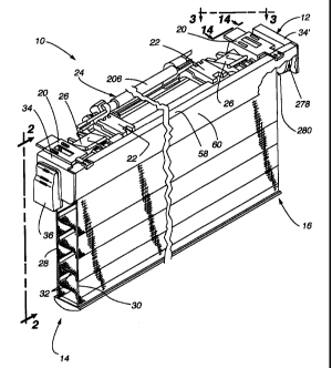
In general, the instant invention relates to a remotely-controllable
retractable covering
for architectural openings 10. As depicted in Figs. 1 and 1A, the apparatus
comprises a
control system mounted in a head rail 12 for extending, retracting, and
otherwise adjusting a
covering 14 attached between the head rail 12 and a bottom rail 16, wherein
the control
system mounted in the head rail may be operated using a remote control 18. In
a preferred
embodiment, two main mounting brackets 20 attach the head rail 12 to a desired
mounting
surface (e.g., a wall above the opening), two battery pack mounting brackets
22 attach a
power supply 24 to the head rail 12, and two limit stops 26 prevent over-
retraction and over-
6
CA 02276071 1999-08-30
extension of the covering 14. A particularly preferred covering 14 for use
with the present
invention comprises a first flexible sheet 28 and a second flexible sheet 30
with vanes 32
attached between these first and second flexible sheets 28, 30, respectively.
The first and
second flexible sheets 28, 30, respectively, are secured to the bottom rail
16. Left and right
end caps 34, 34', respectively, support components, aesthetically shield
various internal
components from view, and include auxiliary support pockets 36 that may be
used in select
applications to position the head rail 12 above an architectural opening to be
covered. As
depicted in Fig. 2, the power supply 24 is hidden from view in the preferred
embodiment
when the head rail 12 is attached to a mounting surface.
Referring next to Figs. 3, 4, 5, 6, 7, and 8, details concerning the elements
comprising
each main mounting bracket 20 are described. Fig. 3 depicts the main mounting
bracket 20
supporting the right end of the apparatus as depicted in Fig. 1. As shown in
Figs. 3 and 4,
each main mounting bracket 20 includes an upper break away tab 38 and a lower
break away
tab 40. These upper and lower break away tabs 38, 40, respectively, may be
used to properly
distance the head rail 12 from the mounting surface. If the tabs 38, 40 are
not required, they
may be broken away from the remainder of the main mounting brackets 20. As
shown to best
advantage in Fig. 3, each main mounting bracket 20 comprises four adjustable
mounting
slots 42, two on a top surface 43 and two on a back surface 45.
Mounted in the center of each main mounting bracket 20 is a pressure strip 44,
which,
in the preferred embodiment, is metallic. The pressure strip 44 is shown to
best advantage in
Figs. 5 and 8. In Fig. 8, it is clearly shown that the pressure strip 44
includes a pair of holes
including a locking tab hole 46 and a second hole 48. Near a distal end 50 of
the pressure
strip 44, a notch 52 is formed on each side of the pressure strip 44, and the
pressure strip 44 is
slightly bent downward adjacent the notches 52 on the side of the notches 52
closest to the
second hole 48.
Fig. 8 also includes an isometric view of a retention clip 54. The retention
clip 54
comprises a downward projecting portion 56, which snaps over the front of a
top edge 58 of
an arcuate cover 60 (Fig. 1) when the mounting bracket 20 is positioned on the
arcuate
cover 60 (see Figs. 3, 4, and 6). The retention clip 54 also includes a first
upper guide 62, a
second upper guide 64, and a lower guide 66. When the retention clip 54 is
slid onto the
distal end 50 of the pressure strip 44, the portion of the pressure strip 44
between its distal
7
CA 02276071 1999-08-30
end 50 and the notches 52 is guided into the slot defined between the lower
guide 66, and the
first and second upper guides 62, 64, respectively, (see Figs. 5 and 6). Fig.
5 shows the first
and second upper guides 62, 64, respectively, in position over the top surface
of the section
between the distal end 50 and the notches 52. Fig. 6 shows the same
relationship between the
first and second upper guides 62, 64, respectively, and the section between
the distal end 50
and the notches 52; and Fig. 6 also depicts the lower guide 66 of the
retention clip 54 riding
on the bottom surface, as depicted, of the pressure strip 44 between its
distal end 50 and the
notches 52 in the pressure strip 44.
As seen to best advantage in Figs. 5 and 8, a pair of detents 68 are formed in
the
retention clip 54 beneath the first upper guide 62. When the pressure strip 44
is inserted into
the retention clip 54, these detents 68 snap into the notches 52 in the
pressure strip 44. Once
the retention clip 54 is thereby retained on the distal end 50 of the pressure
strip 44, the
opposite end of the pressure strip 44 is inserted under a retention bridge 69
and into a slot 70
formed in the top surface 43 of the main mounting bracket 20. This slot 70 in
the top
surface 43 of the main mounting bracket 20 may be seen to best advantage in
Figs. 3 and 5.
When the pressure strip 44 is inserted completely into the slot 70 in the top
surface 43, a
locking tab 72 snaps through the locking tab hole 46 in the pressure strip 44
(see Figs. 3 and
7), thereby retaining the pressure strip 44 in the slot 70 in the top surface
43 of the main
mounting bracket 20.
Once the main mounting bracket 20 is assembled by slipping the distal end 50
of the
pressure strip 44 into the retention clip 54, and then slipping the opposite
end of the pressure
strip 44 into the slot 70 in the top surface 43 of the main mounting bracket
20, the main
mounting bracket 20 may be attached to the head rail 12. As may be seen to
best advantage
in Figs. 4 and 6, the main mounting bracket 20 attaches to a mounting lip 74
of the arcuate
cover 60. Each main mounting bracket 20 includes an upper leg 76 and a lower
leg 78
defining a slot 80 therebetween (Fig. 6). As seen to best advantage in Fig. 5,
both the upper
leg and the lower leg (shown in phantom) extend laterally from side-to-side of
the main
mounting bracket 20. When the main mounting bracket 20 is forced onto the
arcuate
cover 60, it snaps into and retains its position thereon. In order to more
clearly understand
how each main mounting bracket 20 snappingly attaches to the arcuate cover 60,
several
features of the arcuate cover 60 must first be described.
8
CA 02276071 1999-08-30
t r
Referring to Figs. 4, 6, and 21, the elements of the arcuate cover 60 (labeled
in Fig. 1)
are described. Each of these figures shows the cross section of the arcuate
cover 60. The
arcuate cover 60 includes a top edge 58 that is substantially perpendicularly
joined to a front
surface 82 that is curved toward the covering 14 at the arcuate cover's 60
bottom edge 84.
Moving toward the rear of the head rail 12 (to the right in Figs. 4, 6, and
21) from the
intersection of the top edge 58 with the front surface 82 of the arcuate cover
60 along the
bottom or inside portion of the top edge 58, a downward ridge 86 is first
encountered.
Continuing toward the rear of the head rail 12, the top edge 58 slopes
downward at a
shoulder 88 to the mounting lip 74, which extends along the full longitudinal
length of the
back side of the top edge 58 of the arcuate covering 60. The lowest point of
the downward
ridge 86 and the under side of the mounting lip 74 are substantially coplanar
as seen to best
advantage in Fig. 6. Moving downward, as depicted, along the front surface 82
of the arcuate
cover 60 from the intersection of the front surface 82 with the top edge 58, a
support ledge 92
is encountered on the inside, as depicted, of the front surface 82. Continuing
substantially
horizontally from the support ledge 92, a support ridge 94 is next
encountered. The support
ledge 92 and the support ridge 94 are substantially coplanar. A sloped channel
96 is defined
between the support ledge 92 and the support ridge 94. An upper trough 98 is
defined below
the support ledge 92 between the back side of the front surface 82 and one
side of the sloped
channel 96. Near the bottom edge 84 of the front surface 82 of the arcuate
cover 60 a lower
trough 100 is defined. The left and right end caps 34, 34', respectively, each
has an arcuate
portion (not shown) defined on its inside surfaces that engages the upper and
lower
troughs 98, 100, respectively, on the inside of the front surface 82 of the
arcuate cover 60.
Thus, the end caps 34, 34' are frictionally held onto the arcuate cover 60 by
the upper and
lower troughs 98, 100, respectively.
Referring again to Figs. 4 and 6, attachment of the main mounting brackets 20
to the
arcuate cover 60 is now described. The lower leg 78 of each main mounting
bracket 20
includes a split tongue 102 having a compression slot 104 across its entire
width. In other
words, the compression slot 104 shown in cross section in Figs. 4 and 6
extends through the
lower leg 78 from one lateral edge of the lower leg 78 to the other lateral
edge. When the
mounting bracket 20 is forced onto the arcuate cover 60, the split tongue 102
portion of the
lower leg 78 is inserted into the "pocket" formed by the underside of the
mounting lip 74, the
9
CA 02276071 1999-08-30
4 y
downward ridge 86, the support ledge 92, and the support ridge 94. Since the
top-to-bottom
thickness of the split tongue 102 of the lower leg 78 is slightly greater than
the vertical
distance between the plane defined by the downward ridge 86 and the inside of
the mounting
lip 74, and the plane defined by the support ledge 92 and the support ridge
94, the split
tongue 102 is compressed slightly as it is inserted into the previously
defined pocket. The
compression slot 104 thereby decreases in size as the split tongue 102 is
forced into the
pocket. Since the upper and lower portions of the split tongue 102 resist this
compression,
this resistance helps maintain the main mounting bracket 20 in position.
While the split tongue 102 is being inserted into the above-defined pocket,
the slot 80
defined between the upper leg 76 and the lower leg 78 of the main mounting
bracket 20 slides
over the mounting lip 74 on the top edge 58 (see Fig. 6). When the mounting
lip 90 is
completely seated into the slot 80, the downward projecting portion 56 of the
retention
clip 54 snaps over the corner of the top edge 58. The main mounting bracket 20
is thus held
securely in position by the split tongue 102, slot 80, and retention clip 54.
In particular, the
main mounting bracket 20 cannot move further leftward in Fig. 6 because the
base of the
mounting lip 74 is pressing against the bottom of the slot 80, and the main
mounting
bracket 20 will not move rightward in Fig. 6 because of the downward
projecting portion 56
of the retention clip 54. Similarly, up-and-down motion of the main mounting
bracket 20 is
inhibited by the interaction between the lower leg 78, the upper leg 76, the
retention clip 54,
and the arcuate cover 60. If it becomes desirable to remove the main mounting
bracket 20
from the arcuate cover 60, the downward bias generated by the pressure strip
44 that keeps
the retention clip 54 clipped over the arcuate cover 60 may be overcome by
lifting upward on
the retention clip 54, for example, by pressing a thumb upward against the
downward
projecting portion 56 of the retention clip 54 to force it onto the top edge
58 of the arcuate
cover 60. When the downward projecting portion 56 of the retention clip 54 is
thus
disengaged from the arcuate cover 60, the main mounting bracket 20 may be
pulled rightward
in Figs. 4 and 6 with sufficient force to completely remove the main mounting
bracket 20
from the arcuate cover 60.
Referring next to Figs. 1, 3, 9A, 9B, 21, 22, 23, and 24, construction of a
limit stop 26
and attachment of the limit stop 26 to the arcuate cover 60 is described next.
As clearly
depicted in the preferred embodiment of Figs. 1 and 3, the present invention
includes two
CA 02276071 1999-08-30
, t+
limit stops 26 that prevent over-retraction and over-extension of the covering
14. Fig. 9A is
an exploded, isometric view of one limit stop 26. As shown in this figure,
each limit stop 26
comprises four main components: a mounting half 106, a working half 108, a
biasing
spring 110, and a hinge pin 112.
Looking first at the working half 108, one edge comprises a plurality of
alternating
hinge portions 114. In the preferred embodiment, these hinge portions 114 each
comprise
approximately half of a hinge section. Corresponding hinge portions 116 are
located on the
mounting half 106. The hinge portions 114 on the working half 108 interlock
with the hinge
portions 116 on the mounting half 106, thereby forming a hinge channel to
accommodate the
hinge pin 112. When the mounting half 106 and the working half 108 of the
limit stop 26 are
assembled, the hinge pin 112 is slid through the channel defined by the hinge
portions 114,
116, and the hinge pin 112 is slid through a loop in the central portion of
the biasing
spring 110 to maintain the spring's position between the mounting half 106 and
the working
half 108. A spring groove 118 is cut in the top portion, as depicted, of the
main body 113 of
the working half 108, and a similar spring groove (not shown) may be formed in
the middle
one of the retention fingers 122 on the mounting half 106. Two pivot stops 124
are mounted
on the working half 108 of the limit stop 26. These pivot stops 124 comprise
plate-like
surfaces near the hinge edge of the working half 108. Two of the hinge
portions 116 on the
mounting half 106 comprise extensions 126 that impact the pivot stops 124 if
the assembled
limit stop 26 starts to flex too greatly in one direction about the hinge pin
112. For example,
in Figs. 9A and 21, if the mounting half 106 were held stationary and the
working half 108
were rotated far enough counter-clockwise, the extensions 126 on the mounting
half 106
would impact the pivot stops 124 on the working half 108 of the limit stop 26,
thereby
preventing excessive upward or counter-clockwise rotation of the working half
108 of the
limit stop 26.
Referring to Fig. 9A, the mounting half 106 of the limit stop 26 includes
three
retention fingers 122 in the preferred embodiment. The retention fingers 122
are suspended
above the main body 128, thereby forming a "pocket" between the main body 128
and the
retention fingers 122. On a distal edge of the main body 128 is a
substantially vertical
projection 130.
11
CA 02276071 1999-08-30
. r
Referring now to Fig. 21, when the mounting half 106 of the limit stop 26 is
slid onto
the top edge 58 of the arcuate cover 60, the substantially vertical projection
130 on the distal
edge of the main body 128 snaps into an upper channel 132 (clearly visible in
Figs. 4 and 6)
defined by the front surface 82 of the arcuate cover 60 and the downward ridge
86 on the
underside of the top edge 58 of the arcuate cover 60, while the retention
fingers 122
frictionally engage the top surface of the mounting lip 74 and the main body
128 slides under
the mounting lip 74 and the downward ridge 86. The limit stop 26 is thereby
attached to the
arcuate cover 60 in close frictional engagement therewith.
As shown in Figs. 9A, 9B, and 21, the working half 108 of the limit stop 26
includes
two bottom rail stop arms 134. The function of the bottom rail stop arms 134
will be
described further below with reference to Fig. 24. The underside of the
working half 108 (see
Fig. 9B) includes two curvilinear portions 136, which ride on the outer
surface of the
covering 14 as it is rolled onto a roll bar 138 (see Fig. 23). Where these
curvilinear
portions 136 intersect the main body 113, a pocket 140 is defined (most
clearly visible on the
right-hand edge of Fig. 9A). As shown in Fig. 21, this pocket 140 helps
prevent over-rotation
of the roll bar 138 and over-extension of the covering 14. If, for some
reason, the apparatus
attempts to over extend the covering 14, a forward extending stop rib 142 of
the roll bar 138
gets trapped in the pocket 140 defined behind the curvilinear portions 136
(Fig. 21). When
the forward extending stop rib 142 is thus captured by the pocket 140, a motor
144 (Fig. 12)
rotating the roll bar 138 is stalled, preventing over-rotation of the roll bar
138. From the
direction depicted in Fig. 21, the roll bar 138 rotates clockwise during
extension of the
covering 14 and counter-clockwise during retraction of the covering 14.
Starting from the position shown in Fig. 21, when it is time to retract the
covering 14,
the roll bar 138 is caused to rotate counter-clockwise by the gear motor 144
(the gear motor is
clearly visible in Fig. 12, for example). The curvilinear portions 136 of the
working half 108
of the limit stop 26 are designed to permit retraction of the covering 14 even
after the
apparatus has attempted to overly extend the covering 14. The shape of the
forwarding
extending stop rib 142 also helps in this regard since it has an arched back
surface that
impacts the curvilinear portions 136 during retraction of the covering 14
(i.e., during the first
counterclockwise rotation of the roll bar 138 as depicted in Fig. 21).
12
CA 02276071 1999-08-30
~ =
Referring now to Figs. 1, 3, 11A, 11B, 11C, and 11D, attachment of the power
supply 24 to the head rail 12 is described next. Referring first to Figs. 3,
11A, and 1 1B, the
portions of each battery pack mounting bracket 22 that mounts it to the
arcuate cover 60 are
described next. First and second upper legs 146, 148, respectively, extend
over a
substantially longer tongue 150 having a substantially rectangular port or
window 152 in it
(Fig. 11A). A pair of slots 154 are formed where the first and second upper
legs 146, 148,
respectively, intersect the base of the tongue 150 (Fig. 11A). A flexible arm
156 (Fig. 11B)
extends from the side of the port 152 nearest the base of the tongue 150 and
substantially fills
the port 152. Near the free end of the flexible arm 156, a pair of ridges 158,
160 on the
underside of the flexible arm 156 define a channel 162. When the battery
mounting
bracket 22 is in position on the arcuate cover 60, the tip 151 (see Fig. 11A)
of the tongue 150
extends into the "pocket" defined by the downward ridge 86, the underside of
the mounting
lip 74, the support ledge 92, and the support ridge 94 (the support ledge 92
and the support
ridge 94 are clearly shown in Fig. 6). The two slots 154 between the first and
second upper
legs 146, 148, respectively, and the tongue 150 frictionally engage the
mounting lip 74, and
the channel 162 in the flexible arm 156 captures the support ridge 94, with
the second
ridge 160 of the flexible arm 156 being accommodated by the sloped channel 96
integrally
formed in the arcuate cover 60 (Fig. 11B).
Referring next to Figs. 1, 2, 10, 11 A, 11 C, and 11 D, the power supply 24
and
hardware for mounting it to the head rail 12 are next described. As shown to
best advantage
in Figs. 1 and 2, the power supply 24 is mounted on the back side of the head
rail 12 and is
thereby substantially hidden from view. Fig. 11 A is an exploded view of the
components
comprising the power supply 24. The battery pack mounting brackets 22 are
attached to the
arcuate cover 60 as previously described. The appropriate distance, which is a
function of the
length of the battery tube (or battery pack) 206 which itself is a function of
the energy
requirements of the control system, is established between the mounting
brackets 22 using a
distancing strip 164 (see Figs. 10 and 11A). As shown in Figs. 10 and 11A, the
distancing
strip 164 has a lip 166 on each end of it and a hole 168 near each end of it.
The lip 166 on
one end of the distancing strip 164 clips over one mounting bracket 22, while
the lip 166 on
the opposite end of the distancing strip 164 clips over the edge of the other
battery pack
mounting bracket 22. The distancing strip 164 in position with the lips 166 so
arranged with
13
CA 02276071 1999-08-30
respect to the battery pack mounting brackets 22 is most clearly shown in Fig.
10. A strip
bed 170 (Fig. 11A) is defined in the bottom of each battery pack mounting
bracket 22, and a
placement pin 172 projects from the bottom of the strip bed 170. The strip bed
170 is
approximately as deep as the distancing strip 164 is thick. Thereby, when the
distancing
strip 164 is properly placed, the placement pin 172 in each battery pack
mounting bracket 22
is accommodated by the holes 168 in the distancing strip 164, and the strip
bed 170 in each
battery pack mounting bracket 22 is substantially filled by the distancing
strip 164.
Once the first and second battery pack mounting brackets 22 are attached to
the
arcuate cover 60, and are arranged the appropriate distance apart by the
distancing strip 164,
the remainder of the power supply 24 may be assembled. A first conductor
terminal plate 174
is attached to a conductor plate bed 176 in an adjustable, conductor-end
anchor piece 178
(Figs. 11A and 11C). The first conductor terminal plate 174 is metal, while
the adjustable,
conductor-end anchor piece 178 is plastic in the preferred embodiment. The
first conductor
terminal plate 174 may be snapped onto pins extending from the conductor plate
bed 176, or
it may be bolted onto the conductor plate bed 176, or the first conductor
terminal plate 174
may be glued directly onto the conductor plate bed 176. Subsequently, a
battery tube support
piece 180 is attached to the adjustable, conductor-end anchor piece 178 (best
seen in Fig.
11C). In the preferred embodiment, the battery tube support piece 180 snaps
onto the
adjustable, conductor-end anchor piece 178. The battery tube support piece 180
includes a
conductor port 182 (Fig. 1 1A). A second conductor terminal plate 184 is
riveted to the
battery tube support piece 180 in the preferred embodiment (see Fig. 1 1C).
Once the adjustable, conductor-end anchor piece 178 and the battery tube
support
piece 180 are fixed to one another in the manner described further below, a
first locking
lug 186 is attached to the adjustable, conductor-end anchor piece 178. The
locking lug 186 is
inserted into a lug hole 188 in the adjustable, conductor-end anchor piece
178. The first
locking lug 186 includes a screwdriver slot 190 in a cylindrical portion 192,
and an irregular,
enlarged portion 194 is adjacent the cylindrical portion 192. The lug hole 188
includes an
expansion slot 196 through the center of it. When the first locking lug 186 is
rotated using a
screwdriver inserted into the screwdriver slot 190, the enlarged portion 194
of the first
locking lug 186 tends to expand the expansion slot 196, thereby preventing the
adjustable,
conductor-end anchor piece 178 from sliding in the first battery pack mounting
bracket 22.
14
CA 02276071 1999-08-30
The adjustable, conductor-end anchor piece 178 includes a first lip 198 and a
second lip 200
near its bottom surface (Fig. 11C). Once the first locking lug 186 is inserted
into the lug
hole 188 in the adjustable, conductor-end anchor piece 178, and after the
first conductor
terminal plate 174 has been attached to the adjustable, conductor-end anchor
piece 178, and
the battery tube support piece 180 has been attached to the adjustable,
conductor-end anchor
piece 178, the first lip 198 may be slid into a first groove 202 of the first
battery pack
mounting bracket 22, while the second lip 200 is slid into a second groove 204
of the first
battery pack mounting bracket 22. When the adjustable, conductor-end anchor
piece 178 is
thus slid into the first battery pack mounting bracket 22, the anchor piece
178 rides on top of
the distancing strip 164, thereby keeping the distancing strip 164 in its
strip bed 170, and
keeping the first locking lug 186 in the lug hole 188 in the anchor piece 178.
Once the anchor
piece 178 is positioned at a desired location, the first locking lug 186 may
be rotated to
expand the expansion slot 196 and thereby nonpermanently fix the anchor piece
178 to the
first battery pack mounting bracket 22.
The power supply 24 on the preferred embodiment also includes a side-by-side
battery
tube 206, which, in the preferred embodiment, holds eight AAA batteries 208.
One end of
the battery tube 206 includes a fixed end cap 210 having two external
conductor strips on it.
The second external conductor 212 is visible in Fig. 11 A. The opposite end of
the battery
tube includes a removable end cap 214 having a conductive strip 216 on its
inner surface to
connect the four batteries 208 in one side of the battery tube 206 in series
with the four
batteries 208 on the opposite side of the battery tube 206. The removable end
cap 214 also
includes a figure eight portion 218, which fits into an end of the side-by-
side battery tube 206
until the conductive strip 216 contacts the batteries 208 in the battery tube
206. The
removable end cap 214 also includes a cylindrical portion 220 that is cradled
by a
compression spring slider piece 222 (see Fig. 11D). When the fixed end cap 210
of the
battery tube 206 is properly inserted into the battery tube support piece 180,
the external
conductors on the fixed end cap 210 make electrical contact with the first and
second
conductor terminal plates 174, 184, respectively (both may be seen in Fig.
11C). In
particular, the second external conductor 212 on the fixed end cap 210 makes
electrical
contact with the second conductor terminal plate 184, which is riveted to the
conductor
port 182 in the battery tube support piece 180. Similarly, the first external
conductor on the
CA 02276071 1999-08-30
fixed end cap 210 makes electrical connection with the first conductor
terminal plate 174
mounted in the conductor plate bed 176 of the adjustable, conductor-end anchor
plate 178.
As shown in Fig. 11C, a first wire lead 224 is soldered to the first conductor
terminal
plate 174, and a second wire lead 222 is soldered to the second conductor
terminal plate 184.
The cylindrical portion 220 of the removable end cap 214 is supported by the
compression spring slider piece 222 (Figs. 10 and 11D). The compression spring
slider
piece 222 includes an arcuate support surface 228 that cradles the cylindrical
portion 220 of
the removable end cap 214. An arcuate outer wa11230 also engages the
cylindrical
portion 220 of the removable end cap 214. An abutment surface 232 extends
between the
arcuate support surface 228 and the arcuate outer wa11230, and this abutment
surface 232
presses against the end of the removable end cap 214, holding it in position.
One side of the compression spring slider piece 222 includes a range-limiting
bracket
234. The range-limiting bracket 234 extends around and behind an upright
wa11236 of a
compression spring anchor piece 238. A compression spring 240 maintains
pressure between
the compression spring anchor piece 238 and the compression spring slider
piece 222. The
compression spring slider piece 222 and the compression spring anchor piece
238 each
includes a spring-mounting pin 242 having an outside diameter that is
substantially the same
size as the inside diameter of the compression spring 240. The compression
spring 240 may
be thereby slid onto the spring-mounting pins 242.
To assemble the three primary components that support the removable end cap
214, a
second locking lug 244 (which is the same as the first locking lug 186 in the
preferred
embodiment) is inserted into a lug hole 246 in the compression spring anchor
piece 238. This
lug hole 246 (visible in Figs. 11A and 1 1D) similarly is divided by an
expansion slot 248 in
the base of the compression spring anchor piece 238. The compression spring
anchor piece
238 includes a first lip 250 and a second lip 252. The first lip 250 is
slidably engaged in a
first groove 254 of the second battery pack mounting bracket 22, while the
second lip 252 of
the compression spring anchor piece 238 is slidable engaged in a second groove
256 of the
second battery pack mounting bracket 22. Since the first and second battery
pack mounting
brackets 22 are the same in the preferred embodiment, the first groove 254 of
the second
battery pack mounting bracket is the same as the first groove 202 of the first
battery pack
mounting bracket. Similarly, the second groove 256 of the second battery pack
mounting
16
CA 02276071 1999-08-30
bracket is the same as the second groove 204 of the first battery pack
mounting bracket.
When the anchor piece 238 is thus slid into the second battery pack mounting
bracket 22, the
underside (not labeled) of the anchor piece 238 keeps the distancing strip 164
in the strip bed
170 of the second battery pack mounting bracket 22, and the second locking lug
244 is held in
the lug hole 246. The compression spring slider piece 222 also includes a
first lip 258 and a
second lip 260. The compression spring 240 is slid over the mounting pin 242
of the anchor
piece 238, and then the first and second lips 258, 260, respectively, of the
compression spring
slider piece 222 are slid into the first and second grooves 254, 256,
respectively, of the
second battery pack mounting bracket 22, while ensuring that the range-
limiting bracket 234
is placed around the upright wa11236 of the compression spring anchor piece
238. Once the
anchor piece 238 and the slider piece 222 are each inserted into the grooves
254, 256 of the
second battery pack mounting bracket 22, and the compression spring 240 is
properly placed
between these two pieces 238, 222, they may be placed in a desired position
along the first
and second grooves 254, 256, respectively. Once the anchor piece 238 is
properly positioned,
a screwdriver blade is inserted into the screwdriver slot of the second
locking lug 244, and the
second locking lug 244 is rotated to spread the expansion slot 248 and thereby
hold the
compression spring anchor piece 238 in the desired position in the first
groove 254 and
second groove 256 of the second battery pack mounting bracket 22. The
compression spring
anchor piece 238 thereby also keeps the compression spring slider piece 222
from falling out
of the first groove 254 and second groove 256 of the second battery pack
mounting bracket
22.
If the slider piece 222 slides in a first direction, it eventually compresses
the
compression spring 240 enough that the slider piece 222 cannot slide any
further in the first
direction. If, on the other hand, the slider piece 222 slides in the opposite
direction, the
range-limiting bracket 234 eventually gets caught by the upright wa11236 of
the compression
spring anchor piece 238. When the removable end cap 214 is properly mounted to
the end of
the battery tube 206, it may be slid into the compression spring slider piece
222. In order to
insert the battery tube 206 into position, it may be necessary to manually
force the slider piece
222 toward the anchor piece 238, thereby compressing the compression spring
240 to provide
sufficient space to slip the cylindrical portion 220 of the removable end cap
214 into
frictional engagement with the arcuate support surface 228 and the arcuate
outer wall 230 of
17
CA 02276071 1999-08-30
the compression spring slider piece 222. When the compression spring 240 is
permitted to
force the compression spring slider piece 222 away from the compression spring
anchor piece
238, the pressure generated by the spring 240 maintains the battery tube 206
in the desired
position between the battery tube support piece 180 and the compression spring
slider piece
222.
Figs. 11 C and 11 D show details concerning the hardware that support the ends
of the
battery tube 206 depicted in Fig. 11A. Referring first to Fig. 11C, details
concerning the
adjustable, conductor-end anchor plate 178 and the battery tube support piece
180 are
described next. Fig. 11C shows details of the two pieces that support the
fixed end cap 210
of the battery tube 206, namely the adjustable, conductor-end anchor piece 178
and the
battery tube support piece 180. The conductor-end anchor piece 178 includes a
conductor
plate bed 176 integrally formed therein (see Fig. 11A for a clear view of the
conductor plate
bed 176). As shown in Fig. 11C, the first conductor terminal plate 174 is
mounted in the
conductor plate bed 176, and a first wire lead 224 is soldered to the first
conductor terminal
plate 174. Near the mid section of the conductor end anchor piece 178 are two
upright
support arms 262, each having a hole in its distal end (see Fig. 11C). These
substantially
vertical upright support arms 262 flex outward slightly so that the holes in
the support arms
262 will snap over the mounting pins 264 on the battery tube support piece 180
when the
battery tube support piece 180 is snapped into position.
On the left end of the conductor-end anchor piece 178, as depicted in Fig.
11C, is a
lug hole 188 and expansion slot 186, which are both integrally formed in the
conductor-end
anchor piece 178. The lug hole 188 rotatably accommodates the cylindrical
portion 192 of
the first locking lug 186. The bottom side (not shown) of the conductor-end
anchor piece
178, below the lug hole 188 shown in Fig. 11C, is cut out to accommodate the
enlarged
portion 194 of the first locking lug 186. The cylindrical portion 192 has a
screwdriver slot
190 formed therein. When the first locking lug 186 is positioned in the lug
hole 188 and a
screwdriver is used to rotate the locking lug 186, the enlarged portion 194 of
the locking lug
186 expands the expansion slot 196 in a known manner to force the first lip
198 and second
lip 200 apart. Thus, when the first lip 198 of the conductor-end anchor piece
178 is in the
first groove 202 of the first battery pack mounting bracket 22 and the second
lip 200 is in the
second groove 204 of the first battery pack mounting bracket 22, rotation of
the locking lug
18
CA 02276071 1999-08-30
186 nonpermanently fixes the position of the conductor-end anchor plate 178
relative to the
first battery pack mounting bracket 22.
The battery tube support piece 180 includes a pair of mounting pins 264 that
are
pivotally accommodated by the substantially vertical upright support arms 262
of the
conductor-end anchor piece 178. The mounting pins 264 are positioned below the
conductor
port 182 (visible in Fig. 11 A) of the battery tube support piece 180. The
mounting pins 264,
which define the pivot axis of the battery tube support piece 180 are also
mounted below the
center of the abutment surface 266 of the support piece 180 (the center of the
abutment
surface 266 roughly corresponds to the position of the conductor port 182,
which has the
second conductor terminal plate 184 riveted to it in Fig. 11C). Thus, when the
fixed end cap
210 of the battery tube 206 is positioned against the abutment surface 26 of
the battery tube
support piece 180, pressure exerted by the fixed end cap 210 against the
abutment surface 266
tends to rotate the battery tube support piece 180, if at all,
counterclockwise about the
mounting pins 264 depicted in Fig. 11 C. This counterclockwise rotation of the
battery tube
support piece 180 in the holes in the upright support arms 262 of the
conductor-end anchor
piece 178 rotates the trailing edge 268 of the support piece 180 against the
surface of the
conductor-end anchor piece 178.
As clearly shown in Fig. 11C, the second conductor terminal plate 184 is
riveted in
the conductor port 182 (visible in Fig. 11 A), and the second wire lead 226 is
soldered to the
second conductor terminal plate 184, which is visible in Fig. 11 C. When the
battery tube 206
is correctly positioned in the battery tube support piece 180, and the battery
tube support
piece 180 is snapped into position in the conductor-end anchor piece 178, the
batteries 208 in
the battery tube 206 are connected in series with the first wire lead 224 and
the second wire
lead 226. The first and second lead wires 224, 226, respectively, are then
connected to a plug
270, which may be seen in Fig. 3. Once the power supply 24 is positioned on
the back of the
head rail 12, the plug 270 on the end of the first wire lead 224 and the
second wire lead 226 is
plugged into a power connection port 272 visible in, for example, Figs. 3 and
14.
Focusing now on Fig. 1 1D, the details concerning the hardware components that
support the removable end cap 214 of the battery tube 206 are described next.
The
compression spring anchor piece 238 includes a lug hole 246 divided by an
expansion slot
248. The lateral edges of the bottom portion of the anchor piece 238 comprises
a first lip 250
19
CA 02276071 1999-08-30
and a second lip 252. When the anchor piece 238 is correctly positioned in the
second battery
pack mounting bracket 22 (Fig. 1 1A), the first lip 250 rides in the first
groove 254 and the
second lip 252 rides in the second groove 256. Once the anchor piece 238 is
correctly
positioned in the second battery pack mounting bracket 22, the locking lug 244
is rotated in
the lug hole 246 to expand the expansion slot 248 and frictionally bind the
anchor piece 238
in the second battery pack mounting bracket 22. The anchor piece 238 also
includes a
substantially vertical upright wall 236 that has a spring mounting pin 242
integrally formed
thereon. Once the anchor piece 238 is properly positioned, the compression
spring 240 may
be slipped onto the spring mounting pin 242 of the anchor piece 238. The
spring mounting
pin 242 is designed to frictionally fit into the inside of the compression
spring 240. The
compression spring slider piece 222 is next positioned in the second battery
pack mounting
bracket 22 by placing the range-limiting bracket 234 around the upright wall
236 of the
compression spring anchor piece 238 and slipping the first lip 258 and the
second lip 260 on
the bottom lateral edges of the slider piece 222 into the first groove 254 and
second groove
256 on the second battery pack mounting bracket 22.
The side of the abutment surface 232 that is not visible in Fig. 1 1D has a
spring
mounting pin like the pin 242 integrally formed on the compression spring
anchor piece 238.
This spring mounting pin rides inside the opposite end of the compression
spring 240, thereby
trapping the compression spring 240 between the compression spring anchor
piece 238 and
the compression spring slider piece 222. When thus mounted, the compression
spring slider
piece 222 is prevented from sliding off the second battery pack mounting
bracket 22 by the
interaction between the range-limiting bracket 234 and the upright wall 236,
and the
interaction between the first lip 258 and second lip 260 of the slider piece
222 in the first
groove 254 and second groove 256, respectively, of the second battery pack
mounting bracket
22.
The slider piece 222 may, however, slide toward and away from the compression
spring anchor piece 238 a predetermined amount by applying varying amounts of
pressure to
the abutment surface 232 and thereby compressing the compression spring 240 or
permitting
it to expand. The arrangement depicted in Fig. 11D thereby maintains
longitudinal pressure
on the battery tube end caps 210, 214, which enhances the battery tube's
ability to maintain a
complete electrical circuit.
CA 02276071 1999-08-30
Fig. 12 shows a cross-sectional view of the gear motor 144 and the circuit
board
housing 274, which protects a circuit board 276 (see Fig. 16) that controls
operation of the
gear motor 144. In the preferred embodiment, the gear motor 144, which is
powered through
first and second power terminals, 145, 147, respectively, is a reversible,
direct current (dc)
motor. Also shown in Fig. 12 is a signal receiver 278 and a manual operation
switch 280. As
shown in Fig. 13, the circuit board housing 274 includes ports that
accommodate the signal
receiver 278 and a plug 282. Depending upon the particular mounting of the
retractable
covering 14, the signal receiver 278 and the plug 282 may be interchanged to
facilitate the
clearest line of sight from the remote control 18 to the signal receiver 278.
Referring now to Figs. 14 and 15, additional details concerning the drive end
of the
head rail 12 are visible. A power connection port 272 is visible in Fig. 14.
When the power
supply 24 is properly mounted on the head rail 12 as previously described, a
plug 270 (visible
in Fig. 3) connected to the first wire lead 224 and the second wire lead 226
is plugged into the
power connection port 272 shown adjacent the circuit board housing 274 in Fig.
14. The
power connection port 272 is connected by a ribbon cable 284 to the circuit
board 276 inside
of the circuit board housing 274. The gear motor 144 shown in Fig. 12 has a
gear shaft 286
attached to it. The gear shaft 286 is clearly visible in Fig. 15. The distal
end of the gear shaft
includes a pair of locking tabs 288. Surrounding a portion of the gear shaft
286 is a motor
gear 290. In the preferred embodiment, the motor gear 290 comprises fifteen
teeth or splines.
In the preferred embodiment, three orbiting transfer gears 292 slide onto
corresponding
dowels or pivot pins 294 mounted at equal intervals around the motor gear 290
so as to
meshingly engage the motor gear 290. In the preferred embodiment, the orbiting
transfer
gears 292 each comprises twenty-one teeth or splines. Subsequently, an
internal gear 296 is
slid over the orbiting transfer gears 292 so that the internal gear 296 meshes
with the three
orbiting transfer gears 292. In the preferred embodiment, the internal gear
296 comprises
fifty-eight teeth or splines. When the internal gear 296 is sufficiently slid
onto the orbiting
transfer gears 292, the pair of locking tabs 288 on the distal end of the gear
shaft 286 retain
the internal gear 296 in position. As shown to good advantage in Figs. 14 and
15 (see also
Figs. 21 and 22), the internal gear 296 has extended ribs 297 on its outer
surfaces 299. These
extended ribs 297 ride in an alignment channel 301 comprising part of the roll
bar 138. Thus,
when the gear motor 144 drives the internal gear 296, that in turn drives the
roll bar 138
21
CA 02276071 1999-08-30
through the interaction between the extended ribs 297 and the alignment
channel 301. A
plurality of smaller ribs 303 ride on the inner surface of the roll bar 138
when it is mounted
on the internal gear 296.
Fig. 16 is an exploded isometric view of the circuit board 276 in the circuit
board
housing 274. Clearly visible in Fig. 16 is the signal receiver 278 and the
signal receiver
wiring 298 shown in two selectable positions. The signal receiver 278 may be
mounted in
either side of a circuit board housing cover 300, depending upon the intended
mounting
location for the covering 14. In the preferred embodiment, the signal receiver
wiring 298 has
a plug 302 soldered to it that plugs into an appropriate socket 304 on the
circuit board 276.
The ribbon cable 284 that joins the circuit board 276 to the power connection
port 272 (Fig.
14) may be seen in Fig. 16. Also, a rotator counter 306 that provides required
position
information to the electronics may be seen in Fig. 16.
Figs. 17, 18, 19, and 20 show the primary features of the remote control 18.
Fig. 17 is
an isometric view of the top surface of the remote control 18. Clearly visible
in Fig. 17 is a
frequency selection switch 308. In the preferred embodiment, it is possible to
select one of
two control frequencies so that more than one retractable covering 14 may be
separately
controlled by a single remote control 18. Mounted just below the frequency
selection switch
308, as depicted, is a control rocker switch 310. Also shown in Fig. 17 is a
control signal 312
emanating from the end of the remote control 18. Fig. 18 is an exploded
isometric view of
the back side of the remote control 14 showing a battery housing cover 314 and
a locking tab
316 that holds the battery housing cover 314 in position over the three AAA
batteries 318
used by the remote control 18 in the preferred embodiment. Fig. 19 is a top
view of the
remote control 18 and shows further details of the control switches. In
particular, the control
rocker switch 310 includes a raised up arrow 320 and a recessed down arrow
322. Since the
up arrow 320 is slightly raised and the down arrow 322 is slightly recessed,
it is possible to
use the remote control 18 in low light or no light conditions. Also visible in
Fig. 19 is a
transmission indicator LED 324. When the up arrow 320 or down arrow 322 on the
rocker
switch 310 is pressed, the transmission indicator LED 324 lights so that the
user knows that
the remote control 18 is attempting to transmit a signal 312 to the receiver
278 mounted in
the head rail 12. Finally, Fig. 20 shows an end view of the remote control 18
along line 20-20
of Fig. 19. Clearly visible in Fig. 20 is the control signal transmitter port
326 (this port is also
22
CA 02276071 1999-08-30
shown in phantom in Fig. 19). The control signal 312 emanates from the
transmitter port
326. Thus, the transmitter port 326 must be aimed at the receiver 278 during
transmission.
Fig. 21 depicts the limit stop 26 operating to prevent the roll bar 138 from
over-
rotating and thereby over-extending the covering 14. As previously discussed,
if the gear
motor 144 attempts to over-extend the covering 14, the forward extending stop
rib 142 will
engage the pocket 140 defined by the main body 113 and the curvilinear portion
136 of the
working half 108 of the limit stop 26. The locking engagement between the
forward
extending stop rib 142 and the pocket 140 prevents the roll bar 138 from
continuing to rotate.
When the roll bar 138 is thus stopped from rotating, the electronics continue
to command the
drive motor 144 to rotate the roll bar 138, but no rotation results. After a
short duration, the
electronics realize that the gear motor 144 is stalled and command the gear
motor 144 to stop
attempting to extend the covering 14. Fig. 21 also clearly shows a first sheet-
retention
channel 305 retaining the first flexible sheet 28, and a second sheet-
retention channel 307
retaining the second flexible sheet 30.
When the control system is commanded to retract the covering 14, the forward
extending stop rib 142 is easily rotated out of engagement (counterclockwise
in Fig. 21) with
the pocket 140 on the underside of the limit stop 26 and, as the covering 14
is wound around
the roll bar 138, it rolls over the top of the forward extending stop rib 142,
thereby covering
it. When the covering 14 is not fully extended, the forward extending stop rib
142 is covered
or concealed by the covering 14. Thus, if the system is commanded to extend
the covering
14, and the covering 14 is not yet fully extended, the curvilinear portions
136 of the stop limit
26 slide over the exterior surface of the covering 14, and the forward
extending stop rib 142
does not and cannot become trapped in the pocket 140 behind the curvilinear
portions 136.
When the control system is operating properly, the forward extending rib 142
does not get
caught in the pocket 140 since the control system commands extension of the
covering 144 to
stop before it attempts to over-rotate the roll bar 138 and over-extend the
covering 14. This
latter, more typical, operation of the control system is shown in Fig. 22.
The general operation of the remotely-controllable the retractable covering 10
of the
present invention is described next. The covering 14 may be in the
configuration depicted in
Fig. 24, which is in its most retracted configuration. From this fully
retracted configuration,
the operation of the remotely-controllable retractable covering 10 proceeds as
follows. If the
23
CA 02276071 1999-08-30
down arrow 322 on the remote control 18 is pressed and released one time, the
gear motor
144 begins to drive the roll bar 138 to extend the covering 14 (i.e.,
clockwise as depicted in
Figs. 21-24). If no additional buttons are pressed on the remote control 18,
the motor 144
continues to drive the roll bar 138 until the covering 14 is fully extended,
but in a minimum
transmissivity configuration (i.e., the vanes 32 between the first flexible
sheet 28 and the
second flexible sheet 30 are blocking the maximum amount of light and air
transmission
through the covering). This configuration is not shown separately in the
figures, but the
bottom rail 16 would be in a position similar to that depicted in Fig. 23, and
the covering 14
would be otherwise fully extended. Then, if the down arrow 322 is pressed and
released a
second time while the covering 14 is in the fully extended configuration, the
gear motor 144
again rotates the roll bar 138 (clockwise as depicted in Fig. 21) until the
bottom rail 16 is
horizontal and the transmissivity through the covering 14 is at a maximum
(i.e., the vanes 32
between the first flexible sheet 28 and the second flexible sheet 30 are in a
substantially
horizontal configuration). This configuration of the covering 14 is shown in
Fig. 22. When
the blind is in the resulting "fully opened" configuration, any further
pressing of the down
arrow 322 on the remote control 18 has no effect on the configuration of the
covering 14.
If, instead, the up arrow 320 on the remote control 18 is pressed and released
one time
while the covering 14 is in its fully opened configuration (the Fig. 22
configuration), the gear
motor 144 rotates the roll bar 138 until the covering 14 is in its "fully
closed" configuration
(i.e., until the vanes 32 between the first flexible sheet 28 and the second
flexible sheet 30 are
substantially vertical and block the maximum amount of light or air attempting
to pass
through the covering 14). This latter configuration change involves rotating
the roll bar 138
in a counterclockwise direction as depicted in Fig. 21. The covering 14 then
remains in its
fully extended but minimally transmissive configuration until another button
320, 322 is
pressed on the remote control 18. If the up arrow 320 is again pressed and
released, the gear
motor 144 is commanded to drive the roll bar 138 until the covering 14 is in
its fully retracted
configuration (shown in Fig. 24), which is the configuration from which
operation of the
retractable covering commenced in this example.
Whenever the covering 14 is in motion, that motion may be interrupted by
pressing
and releasing either the up arrow 320 or the down arrow 322 on the remote
control 18. The
up-and-down operation of the covering 14 and the transmissivity-adjustment of
the covering
24
CA 02276071 1999-08-30
14 may both be interrupted by pressing either the up arrow 320 or the down
arrow 322 on the
remote control 18. For example, if the gear motor 144 has been commanded to
extend the
covering 14, and the bottom rail 16 is traveling downward but has not yet
reached its lowest
point of travel (see Fig. 23), if either the up arrow 320 or the down arrow
322 on the remote
control 18 is pressed and released, the gear motor 144 is commanded to cease
all motion of
the covering 14. If the down arrow 322 is then pressed and released, the gear
motor 144 will
be commanded to continue extending the covering 14. If, on the other hand, the
up arrow 320
is pressed and released after the covering 14 was stopped, the gear motor 144
will be
commanded to reverse the direction of rotation of the roll bar 138, and will
begin to retract
the covering 14 onto the roll bar 138 (i.e., the roll bar 138 will be rotated
in the
counterclockwise direction as depicted in Figs. 21-24). Similarly, if the
covering 14 is being
retracted and the up arrow 320 or the down arrow 322 is pressed and released,
retraction of
the covering 14 stops. Then, if the up arrow 320 is pressed and released
again, retraction of
the covering 14 commences. If, on the other hand, the down arrow 322 is
pressed and
released after stopping the retraction of the covering 14, the gear motor 144
will begin to
rotate the roll bar 138 so as to extend the covering 14.
Transmissivity of the extended covering 14 is also fully adjustable using the
remote
control 18. When the covering 14 is in its fully extended configuration, the
transmissivity of
the covering 14 (i.e., the amount of light or air that is permitted to pass
through the covering
14) may be adjusted by selectively pressing and releasing either the up arrow
320 or the down
arrow 322. When the covering 14 is in its fully extended configuration, the
gear motor 144
operates in a second, slower speed. Therefore, the transmissivity adjustments
take place at
the slower speed. The counter 306 used to determine the position of the
covering 14
commands the gear motor 144 to operate at the slower speed for a predetermined
number of
counts from the fully extended configuration of the covering 14. The counter
306 is thus able
to inform the gear motor 144 via the circuit board 276 when the covering 14 is
configured for
maximum transmissivity, minimum transmissivity, or any desired level of
transmissivity
between the maximum and the minimum.
The control system of the present invention uses counting as a primary means
of
controlling the position and orientation of the bottom rail 16 relative to the
head rail 12. In
certain situations, the control system may place the gear motor 144 into a
stall as a means of
CA 02276071 1999-08-30
determining what configuration the covering 14 is in. For example, if the gear
motor 144
attempts to over-extend the covering 14, as depicted in Fig. 21, the forward
extending stop rib
142 on the roll bar 138 will engage the pocket 140 behind the curvilinear
portion 136 of the
working half 108 of the limit stop 26. If such capture of the forward
extending stop rib 142
occurs, the gear motor 144 is thereby placed in a stall, which informs the
circuitry that the
gear motor 144 is attempting to over-rotate the roll bar 138 and over-extend
the covering 144.
After being in a stall for a short period, the gear motor 144 is instructed to
stop attempting to
rotate the roll bar 138. A second scenario where the gear motor 144 may be
placed into a
stall occurs when the covering 14 is fully retracted, as shown in Fig. 24. As
shown, in the
fully retracted configuration, an edge of the bottom rail 16 strikes the
bottom rail stop arms
134 on the working half 108 of the limit stop 26. This interaction between the
bottom rail 16
and the stop arms 134 accomplishes two goals. First, when the gear motor 144
rotates the roll
bar 138 sufficiently to drive an edge of the bottom rail 16 into the stop arms
134, the
curvilinear portions 136 on the underside, as depicted in Fig. 9B, of the
working half 108 of
the limit stop 26 are thereby raised off the roll bar 138 and the covering
material 14 that has
collected thereon. Second, when the bottom rail 16 is captured by the bottom
rail stop arms
134, the gear motor 144 ultimately goes into a stall, and the control
electronics recognize the
stall and shut down the gear motor 144. Thus, the covering 14 takes on its
fully retracted
configuration, wherein the bottom rail 16 holds the working half 108 of the
limit stop 26 off
of the actual covering material 14, which prevents the curvilinear portions
136 which ride on
the covering material 14 as it is retracted or extended from creasing or
denting, which may
otherwise occur if the covering 14 is kept in a fully retracted configuration
over an extended
period of time.
It is also possible to control the retractable covering apparatus of the
present invention
without using the remote control 18. A manual operation switch 280 is mounted
to the circuit
board housing 274 and circuit board housing cover 300 (see Figs. 12 and 13,
for example).
Selective pressing of the manual operation switch 280 permits a user to
configure the
covering 14 in any desired configuration that is obtainable through use of the
remote control
18. In general, with each press of the manual operation switch 280, the
control electronics on
the circuit board 276 treat each press of the manual operation switch 280 as
first a press of the
up arrow 320 on the remote control 18 followed by a press of the down arrow
322 on the
26
CA 02276071 1999-08-30
remote control 18, or vice versa. In other words, each time the manual
operation switch 280
is pressed, the control electronics interpret that as alternating presses of
the up arrow 320 and
down arrow 322 on the remote control 18. An exception to this general rule by
which the
control electronics interpret the presses of the manual operation switch 280
occurs when the
covering 14 is in its fully extended configuration. When the covering 14 is in
the fully
extended configuration, the control electronics must determine whether the
user is attempting
to retract the covering 14 or merely adjust the transmissivity of the fully
extended covering
14. For example, if the covering 14 is in its fully extended configuration and
its minimally
transmissive configuration (i.e., the covering 14 has just reached its fully
extended
configuration and stopped), a subsequent press of the manual operation switch
280 is
interpreted by the control electronics as a command to "open" the extended
covering 14,
increasing the transmissivity thereof by rotating the roll bar 138 to move the
vanes 32 to a
more horizontal configuration. If the manual operation switch 280 is again
pressed during
adjustment of the transmissivity, the gear motor 144 is signaled to stop
movement. If the
covering 14 is thus placed in a configuration somewhere between its maximally
transmissive
configuration and its minimally transmissive configuration, a subsequent press
and release of
the manual operation switch 280 will either increase the transmissivity or
decrease the
transmissivity depending upon whether the transmissivity was increasing or
decreasing when
the manual operation switch 280 was pushed to stop motion of the gear motor
144. If the
transmissivity was being increased when the gear motor 144 was commanded to
stop rotating
the roll bar 138, a subsequent press and release of the manual operation
switch 280 will
instruct the control electronics to command the gear motor 144 to continue
increasing the
transmissivity as long as the maximum transmissivity configuration had not yet
been
achieved. If, on the other hand, the transmissivity was being reduced when the
manual
operation switch 280 was pressed to stop rotation of the roll bar 138, a
subsequent press and
release of the manual operation switch 280 will cause the control electronics
to instruct the
gear motor 144 to rotate the roll bar 138 to continue decreasing the
transmissivity until the
minimum transmissivity configuration is obtained or the manual operation
switch 280 is
again pressed, whichever occurs first.
In summary, if the manual operation switch 280 is pressed while the gear motor
144 is
rotating the roll bar 138 and the covering 14 has not yet reached a fully
extended or fully
27
CA 02276071 1999-08-30
retracted configuration, the gear motor 144 will be commanded to stop rotating
the roll bar
138. A subsequent press and release of the manual operation switch 280 will
reverse the
direction of rotation of the roll bar 138.
For example, if the covering 14 was being extended before the gear motor 144
was
instructed to stop rotating the roll bar 138, a subsequent press and release
of the manual
operation switch 280 will result in the gear motor 144 rotating the roll bar
138 so as to retract
the covering 14. On the other hand, if the gear motor 144 was driving the roll
bar 138 so as
to retract the covering 14 when the manual operation switch 280 was pressed to
stop
retraction of the covering 14, a subsequent press and release of the manual
operation switch
280 will cause the control electronics to command the gear motor 144 to rotate
the roll bar
138 so as to extend the covering 14. When the covering 14 is in the fully
extended
configuration (see Figs. 1 and 22), pressing and releasing the manual
operation switch 280
does not necessarily reverse the direction of rotation of the roll bar 138.
The direction of
rotation of the roll bar 138 is only reversed if the transmissivity has
reached a maximum
before the manual operation switch 280 is pressed and released two times. For
example, if
the transmissivity is being increased, but has not yet reached the maximum
transmissivity
configuration, when the manual operation switch 280 is pressed and released,
rotation of the
roll bar 138 stops. If the manual operation switch 280 is again pressed and
released, the roll
bar 138 is rotated in the same direction that it was previously rotating until
the maximum
transmissivity configuration is obtained. Thus, the direction of rotation of
the roll bar 138 is
not always reversed following an interruption or stopping of the motion of the
roll bar 138
while adjusting transmissivity (i.e., while the covering 14 is in its fully
extended
configuration).
Fig. 25A is a block diagram of the control system electronics. Figs. 25B and
25C are
schematic diagrams of the control system electronics. The electronics are
described next
using Figs. 25A, 25B, and 25C. Input power for the electronics is supplied by
one or more
batteries 208 connected in series. Connected between the battery 208 and the
microprocessor
328 is circuitry 330 that provides battery reversal protection, a voltage
regulator, noise filters,
and a fuse to an H bridge. The voltage regulator is always on, and the
quiescent current for
the regulator is about one micro amp. A resistor R1 and two capacitors C2 and
C5 together
filter motor noise and prevent it from affecting the voltage regulator. A
third capacitor C3
28
CA 02276071 1999-08-30
provides additional power filtering. Finally, the fuse F1 provides fault
protection to the H
bridge circuit. The microprocessor 328 has a built in "watch dog" timer that
is used to wake
up the microprocessor from sleep mode. Resistor R2 and capacitor C4 form an
oscillator at
nominally 2.05 MH ( 25%). Resistor RO allows for in-circuit programming.
The receiver 278 in the preferred embodiment is a 40 KHz infrared receiver
connected
to terminals P3 and P4. Power is supplied to the receiver directly from the
microprocessor
328. The output from the receiver 278 (high when idle, low when a valid signal
is being
received) is connected to the microprocessor 328. An external photo-eye may be
connected
to terminal P2 (to board via jumper J1-2). It is automatically used as soon as
it is connected
(and the internal photo-eye is then ignored). Switch S 1 is the manual
operation switch 280,
which is shown, for example, in Fig. 13. A slotted optical sensor 306 is
mounted for rotation
with the roll bar 138. A light emitter used in conjunction with the slotted
optical sensor 306
is on only when the microprocessor 328 needs to check the sensor 306, and is
driven by the
microprocessor 328 with current limiting resistor R3. The output of the sensor
(an open
collector transistor) is connected to a microprocessor pin with an internal
pull-up resistor.
Three leads from the microprocessor 328 control the H bridge: LEFT (left N
MOSFET), RIGHT (right N MOSFET), and RUN (which turns on the appropriate P
MOSFET). The N MOSFETs (Q1A and B) are turned on by placing five volts on the
gate. A
P MOSFET (Q2A or B) will be turned on when the RUN signal is high and either
LEFT or
RIGHT is low. When this happens, Q3A or B will turn on and pull the gate of
Q2A or B to
ground, which turns it on (R4A or B pulls the gate to the same level as the
source, and keeps
the P MOSFET off). This setup only allows a P MOSFET to be on if the N MOSFET
on the
same side is off. If both LEFT and RIGHT are low when RUN is active, then both
P
MOSFETs will turn on and act as a brake.
Diodes internal to the P MOSFETs provide protection from back EMF from the
motor. The output of the H bridge connects to the motor via jumper J3-4, then
via connector
P5 or P6 depending on left versus right-hand operation. Capacitor C5 filters
some of the high
frequency noise from the motor.
All times discussed in the present specification are nominal; actual times
vary by
25%. Also when the IR receiver is turned on, during the first millisecond
(msec) of the
interval the output is ignored to allow the unit to settle.
29
CA 02276071 1999-08-30
The following discusses the modes of operation of the microprocessor 328.
Normal sleep/wake operation: Microprocessor 328 wakes up and checks the
override
button. If it is not pushed, the IR receiver 278 is turned on for 5.5 msec.
Any active IR signal
will cause the receiver 278 to be turned on again for 55 msec looking for a
valid signal.
In sleep, the N MOSFETs are both on (brake), the P MOSFETs are off, the opto-
sensor LED is off, the IR receiver 278 power and signal leads are driven low,
and the option
and manual switches are driven low. This is the minimal power state. Sleep
lasts nominally
300 msec (210 minimum - 480 maximum). This time is set by an RC timer inside
the
microprocessor 328 and is independent of the clock.
If the override button was pushed, then the IR receiver 278 is not turned on
yet. The
motor will be activated in the opposite direction from the last movement, and
then the IR
receiver 278 will start cycling (see below).
If any signals are present during the 5.5 msec test interval, then the
receiver 278 stays
off for 9.5 msec (during this time no other components are on besides the
microprocessor
328). Then the receiver 278 is turned on for 55 msec. During this time, the
receiver 278 is
checked every 160 ,usec. This data is checked by a state machine. At the end
of the interval,
the receiver 278 is shut off. If a valid sequence (our channel either up or
down) was not
received, then the microprocessor 328 goes back to a sleep mode.
If a valid up (down) command was received, and the upper (lower) limit has not
been
reached, then the motor 144 is turned on going up (down). If the command was
up (down),
and the upper (lower) limit has been reached, then the remote button is
checked to determine
if it is held for more than 1.7 seconds. If so, then the limit is over-ridden
and the motor 144
starts in the appropriate direction. If it later stalls, a new limit will be
set. During this check,
the microprocessor 328 stays on the entire time, and the receiver 278 is
cycled 9.5 msec off,
55 msec on.
Motor running: The receiver 278 is cycled 9.5 msec off, 55 msec on. After the
on
time, the status is checked: (1) the button is still held from when the motor
144 started (leave
motor running); (2) the button has been released (leave motor running); or (3)
the button has
been re-pushed which means stop (see below). In a similar fashion the manual
override
button is checked every cycle. If the opto-sensor 306 changes state, then the
stall timer is
reset and the revolution counter is updated depending on the direction the
motor 144 and
CA 02276071 1999-08-30
hence the covering are moving. If the covering is moving up, then it is
checked to determine
if it reached the upper limit, and if so, then the motor 144 is stopped. If
the lower limit is
reached and the covering is moving down, then the motor 144 is stopped.
Finally, the stall
timer is checked. If it expires, then the motor is stopped and a new limit is
set.
Stop: The P MOSFETs are turned off, and after 1 msec, the N MOSFETs are both
turned on (brake), then the manual pushbutton and the IR remote are checked to
determine
that they are no longer pushed, then the microprocessor 328 reverts to a sleep
mode.
Figs. 26, 27, 28, 29, 30, 31, and 32 together comprise a flow chart
representation of
the logic used by the control system of the present invention. The logic may
be implemented
in software or firmware for execution by the microprocessor 328. All times
shown in the
flow chart are nominal. Actual times may vary in the preferred embodiment by
25%. Items
in a box are actions that are performed. Items in a diamond are tests that are
made and the
possible outcomes are written next to the arrows leaving the diamond. An arrow
to a number
goes to that number on another figure.
The following ten scenarios provide insight into how the control system
electronics
follow the logic depicted in Figs. 26, 27, 28, 29, 30, 31, and 32.
Scenario 1: Batteries 208 first inserted, no buttons pushed. Execution starts
with
item 400 in Fig. 26, then 402 to initialize the system. The system then stays
in the idle loop
with items 404, 410, 416, and 420.
Scenario 2: Covering 14 not fully closed, motor 144 is stopped, the down
button 322
on the transmitter 18 is pushed and released, and the user lets it go to the
transition point. We
are somewhere in the idle loop 404, 410, 426, 420 When item 412 completes, the
result of
the test will be yes, moving to condition 2 (i.e., from element 414 on Fig. 26
to element 432
on Fig. 27. Item 434 (Fig. 27) will cycle the IR sensor 278, which will decode
the button, and
we move to condition 4 (i.e., from element 448 on Fig. 27 to element 458 on
Fig. 28), which
executes items 460 and 462, which starts the motor 144 going down, full speed,
and we move
to condition 7 (i.e., from element 464 on Fig. 28 to element 490 on Fig. 30).
We are now in a
loop doing item 492. As the motor 144 turns, the rotating sensor 306 will
change, causing us
to go to condition 8 (i.e., from element 496 on Fig. 30 to element 512 on Fig.
31), and item
520 where we decrement the rotation counter. Assuming we do not reach the
transition point,
we move back to condition 7 (i.e., from element 546 on Fig. 31 to element 490
on Fig. 30)
31
CA 02276071 1999-08-30
and the loop doing item with the motor 144 running at full speed. Task number
1 in item 492
will cause the system to check if the button 310 on the transmitter 18 is
still pushed. When it
is released, this is noted. The motor 144 continues, and we go back to the
loop doing item
492. Finally, the covering 14 reaches the transition point. We go through
items 514, 520,
524, 532, 536 (Fig. 31) and condition 10 (i.e., we move from element 542 of
Fig. 31 to
element 506 of Fig. 30), and item 508 which stops the motor 144 and puts us
back in the idle
loop 404, 410, 416, 420 (Fig. 26).
Scenario 3: Covering 14 not fully closed, motor 144 is stopped, the down
button 322
on the transmitter 18 is pushed then released, and the user lets it go awhile,
then pushes the
button 322 again to stop the covering 14 partially closed. We got to the loop
doing item 492
(Fig. 30) the same as scenario 2. Task number 1 in item 492 will cause the
system to check if
the button 322 on the transmitter 18 is still pushed. When it is released,
this is noted. The
motor 144 continues, and we go back to the loop doing item 492. When the
button 322 is re-
pushed, this same task takes us to condition 10 where we go to item 508, where
we stop the
motor 144. We stay in item 508 until the button is released. Then we go back
to the idle
loop 404, 410, 416, 420 (Fig. 26).
Scenario 4: Covering 14 not fully closed, motor 144 is stopped, the up button
320 on
the transmitter 18 is pushed and released, and the user lets it go to the top
limit. We are
somewhere in the idle loop 404, 410, 416, 420 (Fig. 26). When item 410
completes, the
result of the test in item 412 will be "yes," moving to condition 2 (i.e., we
move from element
414 of Fig. 26 to element 432 of Fig. 27). Item 434 will cycle the IR sensor
278, which will
decode the button 320, and we move to condition 3 (i.e., we move from element
452 in Fig.
27 to element 454 of Fig. 28), which executes items 456 and 462, which starts
the motor 144
going up, full speed, and we now transfer from element 464 of Fig. 28 to
element 490 of Fig.
30. We are now in a loop doing item 492. As the motor 144 turns, the rotation
sensor will
change, causing us to go to condition 8 (i.e., from element 496 of Fig. 30 to
element 512 of
Fig. 31) and item 518, where we increment the rotation counter 306. Assuming
we do not
reach the top, we go back to the loop doing item 492 (Fig. 30) with the motor
144 running at
full speed. Task number 1 in item 492 will cause the system to check if the
button 320 on the
transmitter 18 is still pushed. When it is released, this is noted. The motor
144 continues and
we go back to the loop doing item 492. Finally, the covering 14 reaches the
upper limit. We
32
CA 02276071 1999-08-30
go through items 514, 518, 526 (Fig. 31) and condition 10 (i.e., from element
530 of Fig. 31
to element 506 in Fig. 30), and item 508, which stops the motor 144 and puts
us back in the
idle loop 404, 410, 416, 420.
Scenario 5: Covering 14 not fully open, motor 144 is stopped, the up button
320 on
the transmitter 18 is pushed then released, and the user lets it go awhile,
then pushes the
button 320 again to stop it partially open. We get to the loop doing item 492
(Fig. 30) the
same as scenario 4. Task number 1 in item 492 will cause the system to check
if the button
320 on the transmitter 18 is still pushed. When it is released, this is noted.
The motor 144
continues, and we go back to the loop doing item 492. When the button 320 is
re-pushed,
this same task takes us to condition 10 where we go to item 510, where we stop
the motor
144. We stay in item 510 until the button 320 is released. Then we go back to
the idle loop
404, 410, 416, 420 (Fig. 26).
Scenario 6: Covering 14 at top limit, motor 144 is stopped, the up button 320
on the
transmitter 18 is pushed and held until the limit is over-ridden, and the user
lets it go to the
top stall (or stalls it partially open to set a new upper limit). We are
somewhere in the idle
loop 404, 410, 416, 420 (Fig. 26). When item 410 completes, the result of the
test in item
412 will be "yes," moving to condition 2 (i.e., from element 414 in Fig. 26 to
element 432 in
Fig. 27). Item 434 will cycle the IR sensor 278, which will decode the button
320, and we
move to condition 4 (i.e., from element 448 in Fig. 27 to element 458 in Fig.
28), which
executes item 460 and 462, which starts the motor 144 going down, full speed.
We are now
in a loop doing item 492 (Fig. 30). As the motor 144 turns, the rotation
sensor will change,
causing us to go to condition 8 (i.e., from element 496 on Fig. 30 to element
512 on Fig. 31)
and item 520, where we decrement the rotation counter 306. Assuming we do not
reach the
bottom, we go back to the loop doing item 492 with the motor 144 running at
full speed.
When the motor 144 reaches the top, or for any other reason stops rotating
(stalls), the stall
timer will time-out, and we go to condition 9 (i.e., from element 500 in Fig.
30 to element
548 in Fig. 32). We execute item 552 to set the new upper limit, then go to
item 508 (Fig.
30), where we stop the motor 144. Then we go back to the idle loop 404, 410,
416, 420 (Fig.
26). Task number 1 in item 492 (Fig. 30) will cause the system to check if the
button on the
transmitter 18 is still pushed. When it is released, this is noted. The motor
144 continues and
we go back to the loop doing item 492.
33
CA 02276071 1999-08-30
Scenario 7: Brand new covering 14 not at bottom, motor 144 is stopped, the
down
button 322 on the transmitter 18 is pushed and released, and the user lets it
go to the bottom
stall. We are somewhere in the idle loop 404, 410, 416, 420 (Fig. 26). When
item 410
completes, the result of the test in item 412 will be "yes," moving to
condition 2 (i.e., from
element 414 in Fig. 26 to element 432 of Fig. 27). Item 434 will cycle the IR
sensor 278,
which will decode the button 322, and we move to condition 4 (i.e., from
element 448 of Fig.
27 to element 458 of Fig. 28). which executes item 460 and 462, which starts
the motor 144
going down, full speed. We are now in a loop doing item 492 (Fig. 30). As the
motor 144
turns, the rotation sensor will change, causing us to go to condition 8 (i.e.,
from element 496
bf Fig. 30 to element 512 of Fig. 31) and item 520, where we decrement the
rotation counter
306. Assuming we do not reach the bottom, we go back to the loop doing item
492 (Fig. 30)
with the motor 144 running at full speed. When the motor 144 reaches the
bottom, or for any
other reason stops rotating (stalls), the stall timer will time-out, and we go
to condition 9 (i.e.,
from element 500 of Fig. 30 to element 548 of Fig. 32). We execute item 554
(Fig. 32) to set
the new lower limit and transition point, then go to item 508 (Fig. 30) where
we stop the
motor 144. Then we go back to the idle loop 404, 410, 416, 420 (Fig. 26). Task
number 1 in
item 492 (Fig. 30) will cause the system to check if the button 322 on the
transmitter 18 is
still pushed. When it is released, this is noted. The motor 144 continues and
we go back to
the loop doing item 492.
Scenario 8: Covering 14 fully closed, motor 144 is stopped, the down button
322 on
the transmitter 18 is pushed unintentionally and released quickly. We are
somewhere in the
idle loop 404, 410, 416, 420 (Fig. 26). When item 410 completes, the result of
the test in
item 412 will be "yes," moving to condition 2 (i.e., from element 414 of Fig.
26 to element
432 of Fig. 27). Item 434 will cycle the IR sensor 278, which will decode the
button 322, and
we move to condition 5 (i.e., from element 446 of Fig. 27 to element 466 of
Fig. 29), which
starts the loop running item 468. When the user realizes the covering 14 is
already down and
releases the button 322, we go to the idle loop 404, 410, 426, 20 (Fig. 26).
Scenario 9: Covering 14 fully open, motor 144 is stopped, the up button 320 on
the
transmitter 18 is pushed unintentionally and released. We are somewhere in the
idle loop
404, 410, 416, 420 (Fig. 26). When item 410 completes, the result of the test
in item 412 will
be "yes," moving to condition 2 (i.e., from element 414 of Fig. 26 to element
432 of Fig. 27).
34
CA 02276071 1999-08-30
Item 434 will cycle the IR sensor 278, which will decode the button 320, and
we move to
condition 6 (i.e., from element 450 in Fig. 27 to element 478 in Fig. 29),
which starts the loop
running item 480. When the user realizes the covering 14 is already down and
releases the
button 320, we go to the idle loop 404, 410, 416, 420 (Fig. 26).
Scenario 10: Same as scenarios 2-6 but the manual button 280 is pushed instead
of
the IR button 310. Instead of moving to condition 2 we go to condition 1(i.e.,
from element
408 in Fig. 26 to element 422 in Fig. 27). We then go the opposite way that we
moved last
time. We then go to condition 3 (i.e., from element 428 in Fig. 27 to element
454 in Fig. 28)
or 4 (i.e., from element 430 in Fig. 27 to element 458 in Fig. 28) just like
we pushed the
appropriate button on the remote 18. We get to loop doing item 492 (Fig. 30),
and the
scenarios are the same except we note the manual button 280 is released
instead of the remote
button 310. If the manual button 280 is re-pushed (as in scenario 3 or 5),
then we execute
item 508, which stops the motor 144, and then we go to the idle loop 404, 410,
416, 420 (Fig.
26).
Although preferred embodiments of this invention have been described above,
those
skilled in the art could make numerous alterations to the disclosed
embodiments without
departing from the spirit or scope of this invention. Further, all directional
references (e.g.,
up, down, leftward, rightward, bottom, top, inner, outer, above, below,
clockwise, and
counterclockwise) used above are to aid the reader's understanding of the
present invention,
but should not create limitations, particularly as to the orientation of the
apparatus. It is
intended that all matter contained in the above description or shown in the
accompanying
drawings shall be interpreted as illustrative only and not limiting.