Note: Descriptions are shown in the official language in which they were submitted.
CA 02278389 2007-05-04
GLOVE FOR PREVENTING CARPAL TUNNEL SYNDROME
BACKGROUND OF THE INVENTION
1. FIELD OF THE INVENTION
The invention relates to a glove which is
adapted to inhibit or prevent carpal tunnel syndrome.
Particularly, the present invention relates to a glove
assembly which inhibits or prevents carpal tunnel
syndrome while providing increased flexibility and
ease of movement to the wearer of the glove assembly.
2. DESCRIPTION OF RELATED ART
Carpal tunnel syndrome is a common condition
which occurs due to the compression of the median
nerve. It is sometimes referred to as median
compression neuropathy within the carpal canal.
Carpal tunnel syndrome is a particular problem for
workers in industries which require manual operations
with hand held implements or tools or in office
situations wherein a worker may be required to spend
several hours a day resting their hands on a
typewriter or computer terminal and may also be sports
related.
Carpal tunnel syndrome is a clinical syndrome
characterized by numbness, weakness, paraesthesia or
atrophy in the territory of the median nerve distal to
the course through the carpal tunnel in the wrist.
The transverse carpal ligament forms over the median
nerve and may compress the median nerve as a result of
pressure on the hand, producing the above described
symptoms. Traumatic injury is exacerbated because of
the narrowness of the carpal canal. There is no
-1-
CA 02278389 2007-05-04
opportunity for the nerve to be displaced away from
any compressive forces. Compressive injury can be
exacerbated by the development of edema in the tissues
within the canal, which because of the relatively
fixed size, can cause added injury due to compression
of the nerve within the canal. An additional
component of the injury is associated with friction
between the nerve and the adjacent tendons caused by
repetitive motions (injury) which may be worsened by
compression and further reduce the available space
within the canal.
Two types of injury can occur due to
compression of the median nerve. The milder, earlier
form is a demyelination of the median nerve within the
is canal. This type of demyelination occurs early in the
course of compressive injury. However, this form of
injury is also more readily reversible and recovery
can occur in four to six weeks after compression is
relieved. This form of injury can cause motor
weakness due to acute conduction block in the nerve,
however, this weakness is readily reversible.
The second major form of injury includes damage
to the axons themselves. This form of injury occurs
in more severe or prolonged cases and has more
significant implications in that it often leads to
motor weakness. This type of motor weakness tends to
be poorly reversible and often irreversible. Loss of
strength in the thenar muscles can lead to major
disabilities due to the loss of ability to grip or
perform fine dexterous manipulations. This second
form of injury is generally seen in long-standing
cases, many of which, first clinically manifest in a
manner suggestive of the demyelinating form.
-2-
CA 02278389 2007-05-04
If the median nerve is injured at the wrist, as
by wounds or by a dislocation of the lunate bone,
sensation may be lost in the skin on the front of the
index finger and adjacent part of the thumb and over
the back of the distal phalanges of the thumb, index
finger, and middle fingers, and is diminished over a
large area. The brunt of the paralysis falls on the
muscles of the thenar eminence which, in time,
flattens and wastes.
Treatment of carpal tunnel syndrome varies
according to the severity of the condition. Severe
conditions usually require hand surgery to sever the
transverse carpal ligament, whereas in less severe
cases, a splint may be utilized to immobilize the
wrist .
In order to prevent or inhibit a person from
development carpal tunnel syndrome, a number of gloves
and wrist braces have been designed. One such glove
is disclosed in United States Patent Number 4,850,341
to Fabry et al., issued July 25, 1989, which discloses
a glove for inhibiting or preventing carpal tunnel
syndrome which includes a pad configured to cover and
protect the median nerve of the wearer's hand. The
problem with such a device is that the pad is placed
directly over the median nerve and, therefore,
transmits pressure from the external source to the
carpal tunnel ligament. With this type of
relationship, repetitive finger movements can increase
the potential for frictional injury. Additionally,
having a pad oriented directly over the median nerve,
allows for the direct transmission of pressure to the
median nerve.
In order to overcome the problems associated
with the type of glove disclosed in the Fabry et al.
-3-
CA 02278389 2007-05-04
patent, a pad design was disclosed in U.S. Patent
NO. 5,031,640 to applicant, issued July 16,1991 which
eliminates the continuous pressure applied directly
over the median nerve by providing a recess over the
median nerve in a support pad thereby preventing or
eliminating carpal tunnel syndrome. This type of
design has proven to be very effective in inhibiting
or preventing carpal tunnel syndrome. However, it
would be advantageous and desirable to incorporate
into the pad which eliminated continuous pressure
directly over the median nerve, a means of improving
the flexibility and ease of movement to the wearer of
the glove containing such a pad.
SUMMARY OF THE INVENTION
According to the present invention, there is
provided an assembly adapted to inhibit or prevent
carpal tunnel syndrome including a body having a front
side. The assembly includes resilient protection means
secured to the front side of the body for preventing
the application of pressure to a median nerve. The
resilient protection means includes parallel portions
defining a recess extending therebetween and
substantially parallel with both sides of the median
nerve when disposed thereon. The resilient protection
means is interrupted along the extent thereof thereby
imparting greater flexibility and ease of movement to
a user relative to the assembly.
DESCRIPTION OF THE DRAWINGS
Other advantages of the present invention will
be readily appreciated as the same becomes better
understood by reference to the following detailed
-4-
CA 02278389 2007-05-04
description when considered in connection with the
accompanying drawings wherein:
Figure 1 is a particularly cut-away view of an
embodiment of the subject invention;
Figure 2 is a partially cut-away view of a
second embodiment of the subject invention;
Figure 3 is a partially cut-away view taken
along lines 3-3 of Figure 2;
Figure 4 is a partially cut-away view of a
third embodiment of the subject invention;
Figure 5 is a plan view of another embodiment
of the present invention disposed on a hand;
Figure 6 is a cross-section taken along lines
6-6 of Figure 5;
Figure 7 is a plan view of a further embodiment
of the present invention disposed on a hand;
Figure 8 is a cross-sectional view taken along
lines 8-8 of Figure 7; and
Figure 9 is a plan view of another embodiment
of the present invention disposed on a hand.
DETAILED DESCRIPTION OF THE INVENTION
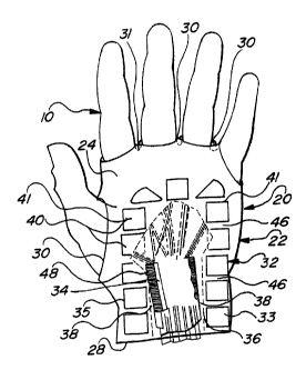
A glove assembly adapted to inhibit or prevent
carpal tunnel syndrome for use on a hand 10 is
generally shown at 20 in the Figures. The hand 10 is
shown broken away to show the median nerve 34 and
adjoining tissue.
It should be noted that although the assembly
is shown as a glove 20, the invention can take the
form of a grip, such as a grip on a bicycle handle bar
or a work tool.
Referring to Figure 1, the assembly 20 includes
a flexible glove body generally indicated at 22. The
glove body includes a front side 24 and a back side 26
-5-
CA 02278389 2007-05-04
defining a wrist opening 28 and at least one finger
opening 30. A resilient protection pad or cushion
mechanism, generally indicated at 32, is secured to
the front side 24 of the glove body 22 for preventing
the application of pressure to a median nerve 34
located in the hand 10. The resilient protection pad
or cushion mechanism 32 includes two parallel portions
33, 35 which define a recess 36 therebetween. The
recess extends substantially parallel with both sides
38 of the median nerve 34 when the glove 20 is worn.
The resilient protection pad or cushion
mechanism 32 includes interruptions 46 which impart
greater flexibility and ease of movement to a wearer
of the glove assembly 20. That is, the pad mechanism
ls 32 is not a flat surfaced cushion, but rather, a
cushion presenting an interrupted surface including
flexible portions at the interruptions. The
interruptions provide points or areas of greater
flexibility allowing for greater flexibility of the
glove at the grip thereof as well as the need for less
padding material. Hence, greater functionability at a
lower cost is achieved.
By way of background, the hand 10 and median
nerve 34 are illustrated in detail in Figure 1. The
median nerve 34 flattens out under the flexor
retinaculum 48 and deep to the superficial palmar arch
and palmar aponeurosis, lying on the flexor tendons,
and divides into five terminal palmar digital branches
and a muscular branch. The tendons and median nerve
34 are packed within and extend under the flexor
retinaculum 48.
The pad or cushion mechanism of the glove
assembly 20 distributes pressure away from the median
nerve 34 and onto the adjacent soft tissue structures,
-6-
CA 02278389 2007-05-04
such as muscle, bone and/or fat. The region of the
pad located over the median nerve 34 has no material
disposed thereover, or may contain a material
sufficiently softer or thinner than the surrounding
material. By eliminating pressure directly over the
median nerve 34, the pressure is also eliminated from
the area directly surrounding the median nerve 34
which thereby allows the tendons and median nerve 34
to move without frictional or direct pressure injury
to the median nerve 34. The greater flexibility of
the pad or cushion mechanism 32 of the present
invention adds to the effectiveness of the
redistribution effect while allowing freer movement to
grip.
Referring more specifically to the glove
assembly 20, the front side 24 and back side 26 of the
flexible glove body 22 are typically sewn together in
a face-to-face relationship to define the glove body
22 or otherwise formed by methods known in the art.
The material comprising the glove body 22 can include
a separate glove front 24 and back 26 which are sewn
together in the face-to-face relationship to define
the glove body 22 or can be formed of a single piece
of material which is sewn together in a sock-like
fashion to define the glove body 22 having the wrist
opening 28 and at least one finger opening 30.
The finger opening 30 can be partitioned or
subdivided into separate finger openings by the
addition of partitions 31 which can include a line of
stitching between the front side 24 and back side 26
of the glove body thereby defining separate finger
openings 30 or can include the addition of a loop of
material which is attached to the front side 24 and
-7-
CA 02278389 2007-05-04
back side 26 to define the finger opening 30.
Additionally, a thumb opening can be included as a
finger opening 30 as shown in Figures 1, 2, and 4.
Again, various glove constructions can be used and
made by those skilled in the art.
The flexible glove body 22 can also include a
fastener or closure (not shown) located near the wrist
opening 28 to secure the glove assembly 20 to the
wrist portion of the hand 10 as a wrist splint. The
io closure can include an elastic band (not shown) sewn
into the flexible glove body 22 directly adjacent to
the wrist opening 28 or can include a VELCRO-type
male/female closure as is well known to those skilled
in the art. Alternatively, the glove can be a slip-on
glove or other style known in the art, although it is
preferable to have a fit which maintains the pads or
cushion mechanism oriented appropriately relative to
the palm of the hand and especially relative to the
median nerve.
Generally, the glove body 22 is constructed of
a flexible or expandable elastic-type material which
conforms to the hand 10 of the user. The flexible
material provides a more secure fit for the glove
assembly 20 and provides a "good feel" to the wearer
of the glove assembly 20. The material which
comprises the glove body 22 can be a flexible material
such as SPANDEX or other similar fabric which imparts
elasticity to the glove assembly 20. However, the
glove body 22 of the glove assembly 20 can be made of
any suitable natural material such as cotton, wool,
and leather, synthetic materials such as nylons
(KevlarTM of Dupont) and polyesters, or any combination
thereof.
-8-
CA 02278389 2007-05-04
As best illustrated in Figures 1, 2, and 4, the
resilient protection pad or cushion mechanism 32 is
secured to the front side 24, better known as the palm
side, of the glove body 22. The resilient protection
pad or cushion mechanism 32 can be made up of several
individual cushions or pads 40 which are secured or
affixed to the front side 24 of the glove body 22.
The pads 40 can be secured by any suitable means such
as sewing, gluing, molding in place or other similar
affixing method. The pads 40 can take on various
forms, as discussed below.
The mechanism also can be a single horseshoe
shaped pad having recessed portions in the surface
thereof. The recessed portions can provide the flex
i5 areas between the relatively raised portions.
The resilient protection pad or cushion 32 can
include at least one pad or cushion 40 disposed on the
front side 24 of the glove body 22. The orientation
of the pad or pads which makes up the resilient
protection pad or cushion 32 defines the major recess
36 which extends substantially parallel with both
sides 38 of the median nerve 34. The recess 36 is
within a predetermined size range for eliminating
pressure directly over and in the vicinity of the
median nerve 34. The recess 36 is placed directly over
the median nerve 24 and extends to cover the
surrounding soft tissues adjacent to the median nerve
36. That is, the median nerve 34 lies safely under
the recess 36 defined by inner margins 41 of the pad
or pads 40. The median nerve 34 is approximately
three millimeters wide between the base of the thumb
and opposite side of the wrist and should have
-9-
CA 02278389 2007-05-04
protection between the crease of the wrist and the
first creases of the palm. Accordingly, the recess 36
must be of greater size than the median nerve 34.
Additionally, the recess 36 should be designed to
allow for some error in positioning the recess 36 of
the resilient protection pad or cushion 32 over the
median nerve 34. The depth of the recess 36 and the
resiliency and hardness of the cushion pad 40 must be
such that when pressure is placed on the hand 10 to
cause depression of the pad 40, the median nerve 34
will not have undue pressure against the external
object placing pressure on the hand 10. In this
manner, the median nerve 34 is supported away from the
surface of the external object.
The pad or pads 40 which make up the resilient
protection pad or cushion mechanism 32 are arranged in
such a pattern that interruptions or non-protected
void spaces are established between adjacent pads 40.
These interruptions or void spaces 46 allow the wearer
of the glove assembly 20 to have greater flexibility
and ease of movement of the hand 10 within the glove
in order to perform manual operations such as typing
or grasping of a tool.
The interruptions or void spaces 46 are
preferably small enough to allow for the increased
flexibility and ease of movement of the hand 10 of the
wearer while, at the same time, preventing the
infiltration or penetration of external objects into
the interruptions or void spaces 46.
The interruptions 46 can also be in the form of
alternating or differentially oriented segments of
softer and harder materials which comprise the
resilient protection pad or cushion 32. The resilient
protection pad or cushion 32 can be comprised of
-10-
CA 02278389 2007-05-04
materials which have alternating segments of materials
which have different flexibilities or firmness in
order to improve the movement of the wearer of the
glove assembly 20.
Referring to Figure 4, an alternative
embodiment of the present invention is shown wherein
the glove assembly 20 includes a cushion pad 40 having
an internal portion 42 removed to improve the
flexibility of the cushion pad 40. The pad 40
includes an interruption or void portion 42 which
imparts greater flexibility to the wearer of the glove
20. This embodiment demonstrates that the
interruption 42 in the resilient protection cushion or
pad 32 can take many different forms thereby providing
is increased flexibility and ease of movement to the
wearer of the glove assembly 20 and without departing
from the spirit of the invention.
Figures 7 and 8 show a further embodiment of
the present invention wherein strips of cushioning
material define the pad mechanism 32'. The strips 32'
can be applied by means known in the art for printing
or extruding a plastic material onto a glove surface.
The strip or segmented design combines flexibility of
the glove with ease of manufacturing. It also allows
for a wide selection of designs that provide a recess
36.
The resilient protection pad or cushion
mechanism 32 which is comprised of the pad or pads 40
must have sufficient firmness to protect the palm of
the hand overlying the median nerve 34 from shock,
pressure, and vibration, but should have sufficient
flexibility to permit the wearer to effectively grasp
and use a tool or perform manually dexterous
-11-
CA 02278389 2007-05-04
operations while wearing the glove 20. The protective
pad or cushion 32 which is comprised of the pad or
pads 40 is preferably constructed of an elastomeric
material, such as foam rubber or other materials such
as closed-cell neoprene, ethylene propylene
terpolymer, styrene butadiene, urethane polymer, and
other similar elastomers.
Any of the materials used to construct the
resilient protection pad or cushion 32 can be formed
first then secured to the front side 24 of the glove
body 22 by means such as gluing or sewing, or the
materials such as polyurethane can be molded,
injected, or foamed-in-place on the front side 24 of
the glove body 22. Molding or injecting operations
such as foaming-in-place allow for the introduction of
air bubbles, void spaces, or closed cells within the
material comprising the protection pad or cushion 32
thereby imparting greater pressure, vibration, and
shock dampening capacity to the protection pad or
cushion 32.
In an additional embodiment illustrated in
Figures 2, 3, 5, and 6, a bridge 44 is shown which
extends across the recess 36 and is affixed to the
resilient protection pad or cushion 32 for preventing
external objects from penetrating the recess 36 and
thereby contacting the median nerve 34 or surrounding
tissue. Also, contact of the bridge by the object
being gripped directs forces from the recess area,
through the bridge laterally to the pads. Thus,
forces are further transferred from the area over the
median recess laterally away therefrom.
Generally, the bridge 44 is constructed of a
material which is less resilient than the material
which comprises the resilient protection cushion or
-12-
CA 02278389 2007-05-04
pad 32. The bridge 44 can take any suitable shape
necessary to prevent the penetration or infiltration
of external objects into the recess but preferably can
be "domed" shaped, as best shown in Figure 3, and
extends away from the surface of the resilient
protection pad or cushion 32. The glove assembly 20
can include at least one bridge 44 but may include a
number of the bridges 44 in order to provide adequate
coverage of the recess 36 and protection of the median
nerve 34 with use of less material.
For example, Figures 2 and 5 show different
constructions of the bridge 44'. In Figure 2, a
multi-strip bridge interconnects parallel pads. In
Figure 5, a single unitary horseshoe shape pad
s.5 includes parallel portions interconnected by wide
bridge strips 44'.
In Figures 5 and 6, the bridge 44' is connected
to the pad 32' by an elastic portion 52. The elastic
part 52 allows for more flexibility when utilizing the
more rigid bridge 44' in combination with the glove.
The elastic portion also further dissipates loads
laterally away from the recess 36.
The bridge 44 can be constructed of any
suitable material including plastic materials such as
polystyrene, polyvinyl chloride, and polyurethane, as
well as metals, utilizing methods well known to those
skilled in the art of plastic injection, molding, and
forming.
Referring to Figure 9, an alternative
embodiment of the resent invention is shown wherein
the glove assembly 20 includes a secondary notch 50
which is situated over the ulnar nerve. This notch
prevents the compression of the ulnar nerve as well as
the median nerve.
-13-
CA 02278389 2007-05-04
Again, each of the species discussed above can
be disposed onto a gripping surface, such as a work
tool grip or machine grip commonly used in the
manufacturing industry. Thus, instead of the user
s wearing a glove including the pad mechanism of the
present invention, the same pad mechanism is disposed
on the machine grip and is then appropriately gripped
by the user. The issue here is not flexibility, since
the grip is usually a solid bar, but rather one of
efficient use of materials and bridging over the
median nerve.
The invention has been described in an
illustrative manner, and it is to be understood the
terminology used is intended to be in the nature of
is description rather than of limitation.
Obviously, many modifications and variations of
the present invention are possible in light of the
above teachings. It is, therefore, to be understood
that within the scope of the appended claims, the
invention may be practiced otherwise than as
specifically described.
-14-