Note: Descriptions are shown in the official language in which they were submitted.
CA 02279232 1999-04-O1
WO 98!14271 PCT/US97/17531
REPLACEABLE ELEMENTS FOR A PARALLEL SEQUENTIAL BIO
POLYMER SYNTHESIS DEVICE
FIELD OF THE INVENTION
The present invention relates generally to a parallel sequential bio-polymer
synthesis apparatus and, more particularly, relates to replaceable elements
for the
use in such an apparatus.
BACKGROUND OF THE INVENTION
Since the advent of bio-polymer synthesis methodologies based upon solid
supports, the synthesis and use of bio-polymers of defined sequence has played
an
increasing, and ever more important, role in therapeutics, diagnostic
medicine,
forensic medicine and molecular biology research. For the purposes of the
present
invention, the term bio-polymers is seen to encompass peptides, polypeptides)
oligo-ribonucleotides, oligo-deoxyribonucleotides, poly-ribonucleotides and
poly-deoxyribonucleotides. In view of the increasing importance of
synthetically
prepared bio-polymers, there is a need in the art for methods and apparatus
that
permit the rapid synthesis of a large number bio-polymers of defined sequence.
The apparatus known in the prior art are capable of the accurate synthesis
of bio-polymers of defined sequences but suffer from the drawback that they do
not
permit a high throughput of synthesis. These prior art devices are based upon
the
attachment of an appropriately prepared monomer, either amino acid or
nucleotide,
to a solid support, or resin, and placing the solid support in a column.
Conventionally, the solid support is shaped into the form of a bead although
other
forms are known. Placement of the solid support beads into a column
facilitates the
sequential application of reagents to the solid support using known fluid
handling
technologies previously developed for use in other column based methodologies.
This arrangement results in apparatus that are capable of synthesizing bio-
polymers
of defined sequences. General methodologies useful in the synthesis of bio-
polymers
are known to those skilled in the art and are taught in numerous prior art
-1-
CA 02279232 1999-04-O1
WO 98114271 PCT/US97117531
references such as U. S. patent no. 4,458,066 to Caruthers et al., U. S.
patent no.
4,415,732 to Caruthers et al., and Bray et al., Journal of Organic Chemistry,
volume
56, pages 6659-6671, 1991, the disclosures of which are specifically
incorporated
herein by reference.
Recently, methodologies based on a parallel sequential reactor have been
developed. This strategy is exemplified by U.S. Patent 5,288,468, issued to
Church
et al. (hereinafter Church), the specification of which is specifically
incorporated
herein by reference. The apparatus of Church is a bio-polymer synthesizer
capable
of the simultaneous synthesis of a number of bio-polymers, each of a defined,
and
potentially different, sequence.
The device of Church includes a number of discrete surfaces upon which
bio-polymers may be synthesized. The discrete nature of the surfaces permits
the
simultaneous preparation of a number of bio-polymers, each of which may have a
different sequence from those prepared at the same time. The surfaces have a
solid
support suitable for the synthesis of bio-polymers adhered to them. The device
also
includes a number of reagent chambers which hold reagents used in the
synthetic
reactions. By movement of the individual surfaces and the chambers, the device
allows individual control over the contact of each surface with each reagent
chamber. The movement of a surface into and out of a sequence of reagent
chambers results in the proper sequence of reactions for the synthesis of a
bio-polymer of desired sequence.
Each discrete surface is attached to the distal portion of a reagent contact
element referred to in Church as a reagent tip. Although, in the interest of
clarity,
the nomenclature of Church will be used when describing the polymer synthesis
apparatus, the use of such nomenclature is not to be construed as limiting the
reagent contact element in any fashion. Each reagent tip is attached to the
end of
a rod that is an integral part of a solenoid-piston assembly, with the
solenoid action
capable of raising or lowering the rod and the attached reagent tip. The
solenoid-piston assemblies are arranged in an array of rows above an array of
reagent chambers. The reagent chambers may consist of troughs cut in the
surface
of a block of inert plastic or may be discrete wells. The block can be moved,
by a
stepping motor, so as to allow a row of solenoid borne reagent tip access to a
given
-2-
r
CA 02279232 1999-04-O1
WO 98/14271 PCT/US97/17531
reagent trough. When lowered a surface (or reagent tip) dips into the contents
of
the reagent chamber positioned beneath it.
Each reagent tip in a row is, by the action of the solenoids, either dipped
into
the trough below it or held above the trough and thus not dipped into the
trough
depending on whether the sequence of the molecule being constructed requires
contact with the reagent in the trough. Reagent tips in adjacent rows are
positioned
above respective adjacent troughs. Dipping of surfaces is controlled
individually and
simultaneously, thus different reactions, i.e., reactions in different
troughs, occur
simultaneously.
The device also includes a system of valves, lines and reservoirs to supply
the
troughs with reagents, a motor to move the trough block, and a computer and
interface to control the actions of the solenoids, valves, and trough block.
The
computer, which is programmed with the sequence of the bio-polymer to be
synthesized on each reagent tip, generates instructions for the proper
sequence of
dipping, trough movement, and valve control, to produce the desired synthetic
reaction, i.e., to effect the simultaneous synthesis of specific bio-polymers
of defined
sequence on specific surfaces.
The reagent tips of Church are made of polypropylene. They are permanently
affixed to the end of the solenoid-piston assembly by gluing. A solid support,
in the
form of a bead, is adhered to the reagent tip by heating the reagent tip until
it is
just molten, then forcing the heated tip into a shallow container filled with
the
appropriate bead. When the beads coupled to a given monomer are used for the
synthesis of a molecule, that monomer forms the first subunit used in the
preparation of the bio-polymer. In the practice of the present invention, any
suitable
material may be used to construct a solid support. The solid support may
fashioned
of glass fiber, cellulose, controlled pore glass beads, polypropylene, tefion,
cellulose,
polyethylene, polysulfones, polyvinylidene difluoride, or any suitable organic
or
inorganic material known to those skilled in the art. Commercially available
solid
supports consisting of beads derivatized to incorporate either nucleotide or
amino
acid monomers may be used. Such solid supports are readily available to those
skilled in the art.
-3-
CA 02279232 1999-04-O1
WO 98/14271 PCT/US97/17531
The reagent tips of Church suffer from several limitations. The method of
manufacture limits the number of solid support beads that may be fastened to
any
one tip. This limits the potential yield of the bio-polymer to be prepared. In
addition, the methodology of Church is slow and cumbersome and requires a
great
deal of hands-on time by the operator in the preparation of reagent tips. This
drastically limits the throughput potential of the device.
SUMMARY OF THE INVENTION.
The apparatus of the prior art are limited in utility. It is an object of the
present invention to provide a reagent contact element that overcomes the
limitations of the apparatus of the prior art.
The apparatus of the prior art are difficult to replace and change. Another
object of the present invention is to provide a reagent contact element
capable of
rapid and simple replacement and change in the bio-polymer synthesis device of
the
prior art.
The apparatus of the prior art have a severely limited production capability.
It is another object of the present invention to provide a reagent contact
element
configured to permit the synthesis of a larger quantity of bio-polymer by each
reagent contact element.
BRIEF DESCRIPTION OF THE DRAWINGS
Figure 1 is a cross-section of one embodiment of the present invention
showing a porous vessel filled with resin attached to the reagent contact
element.
Figure 2 is a cross-section of an embodiment of the present invention in which
porous membranes are attached to the end of the reagent contact element with
solid
support resin trapped between the membrane sheets.
Figure 3 is an embodiment of the present invention showing a reagent contact
element plugged with a porous filter material and sealed with a porous
membrane
with solid support resin trapped there between.
-4-
CA 02279232 1999-04-O1
WO 98/14271 PCT/US97/17531
Figure 4 is a cross section of an embodiment of the present invention showing
a porous filter element molded into the reagent contact element.
Figure 5 shows an embodiment of the present invention where a porous vessel
is attached to the end of the reagent contact element.
Figure 6 shows an embodiment of the present invention wherein the end of
the reagent contact element has been modified with slots so as to permit
greater
reagent access to the interior of the reagent contact element.
Figure 7 shows an embodiment of the invention incorporating axial and radial
locating features.
DETAILED DESCRIPTION OF THE INVENTION
The present invention relates to an interchangeable portion of a chemical
reaction system wherein substances are chemically combined by intermittently
dipping a solid support into a number of reagents. The invention is a
disposable,
replaceable reagent contact element that fits to the end of a rod which may be
brought into intermittent contact with reagents to produce reactions. The two
following features are essential characteristics of each embodiment of the
present
invention: 1) the reagent contact elements will have sites for chemical
reactions; and
2) the reagent contact elements will interface with a rod or other device for
bringing
the element into contact with reagents.
The reagent contact elements may be made of a chemically inert material
which incorporates a solid support resin onto which molecules may be
synthesized
or reacted. The inert portion of the reagent contact element may be formed of
any
suitable material as long as such material is chemically inert to the reagents
required for the subsequent synthesis reactions. In addition to being
chemically
inert, the material used for reagent contact elements must also have a low
water
absorption. The reagent contact elements of the present invention may be made
from a variety of materials such as polypropylene, teflon, cellulose,
polyethylene,
polysulfones, polyvinylidene difluoride or glass as long as the material
possesses the
characteristics of non-reactivity and low water absorption. In a preferred
embodiment, the reagent contact elements are made of polypropylene.
-5-
CA 02279232 1999-04-O1
WO 98/14271 PCT/US97/17531
The reagent contact elements of the present invention are removably attached
to rods which are integral parts of the solenoid-piston assemblies of the
prior art.
The rods are used to transport the reagent contact elements into reactive
media or
fluids. The reagent contact element is fictionally retained upon the rod. The
reagent contact element defines a cylindrical space that is in fluid
communication
with the exterior of the reagent contact element. This permits use of the
reagent
contact element in a device where the rod delivers fluid through the reagent
contact
element as well as in a device wherein the rod has no fluid connections. It
may be
desirable to convey reagents through the reagent contact element and into the
reaction mixture. Alternatively, it may be desirable to convey an inert gas
through
the reagent contact element in order to expel reagents from the reagent
contact
element and/or agitate a reagent mixture into which the reagent contact
element is
submerged.
The reagent contact elements can contain a variety of solid support "seed"
molecules. For the purposes of this application seed molecules is seen to
encompass
amino acids, nucleotides and molecules with reactive functionalities. While
generally
the seed molecules will be monomeric nucleotides or amino acids, one skilled
in the
art will recognize that it is possible, and in some cases desirable, to use a
defined
sequence bio-polymer as the seed molecule. This embodiment will be useful when
it is desired to synthesize a number of molecules that share some but not all
sequences. For specialized uses, it may be desirable to have a reagent contact
element to which various molecules may be attached using the reactive
functionalities.
The solid support molecules may be of any type known to those skilled in the
art. In a preferred embodiment the solid support molecule is controlled pore
glass
beads. The solid support molecules may be attached to the reagent contact
element
by a variety of methodologies. In one embodiment the solid support is attached
to
the reagent contact element using hot melt glue. Alternatively, the solid
support
may be heat welded or ultrasonically welded to the reagent contact element. In
a
preferred embodiment the solid support is ultrasonically welded to the reagent
contact element.
-6-
CA 02279232 1999-04-O1
WO 9$/14271 PCT/US97/17531
In other embodiments, the solid support is attached to the reagent contact
element by trapping the solid support between porous sheets as shown in Figure
2.
The porous sheets may be made of any material so long as the material is not
reactive with the reagents required for synthesis. The porous sheets may be
attached to the reagent contact element by glue, heat welding, or ultrasonic
welding.
In another embodiment, a porous filter plug is inserted into the reagent
contact element to define a cavity at the distal end of the reagent contact
element
as shown in Figure 3. The cavity is filled with solid support material and
then the
end of the contact element is sealed with the porous sheet. Alternatively, a
porous
filter element may be molded into the body of the reagent contact element as
shown
in Figure 4.
In another embodiment, seed molecules are incorporated into the material
making up the reagent contact element. These seed molecules may be monomers or
multimers, nucleotides or amino acids, appropriately blocked for use in
synthesis.
Alternatively, the active site may be a reactive functionality suitable for
subsequent
reaction so as to incorporate a monomer into the reagent contact element.
In another embodiment the solid support is attached directly to the reagent
contact element. This may be accomplished by means of glue, such as hot melt
glue
or silicone glue, or by heat welding or ultrasonic welding. In an alternative
embodiment, a membrane . that has active sites may be attached to the reagent
contact element. For example, the DNA synthesis membrane described in U.S.
Patent 4,923,901 to Koester et al., the specification of which is specifically
incorporated herein by reference, may be attached to the reagent contact
element.
When membranes are used one or more membranes may be attached to a single
reagent contact element so as to provide more reactive sites.
The reagent contact elements are designed to fit in an array of holes in a
tray
for easy insertion/removal from an array of pins. The array of holes in the
tray may
be fashioned so as to be substantially identical to the array of pins in the
parallel
sequential bio-polymer synthesizer. Both the array of pins and the array of
holes
in the tray may be fashioned so as to be compatible with devices currently in
use in
the art. For example, the spacings of the pins in the apparatus and the holes
in the
tray may be the same as that in a standard 96-well microtiter plate. The
reagent
_7_
CA 02279232 1999-04-O1
WO 98/14271 PCT/US97/17531
contact elements may be delivered as individual reagent contact elements in a
tray
or alternatively the reagent contact elements may be attached to one another
in an
array rather than loose in the tray, i.e., the reagent contact elements may be
molded
into one piece. The reagent contact elements thus molded may be used all at
once
or alternatively one or more reagent contact elements may be removed from the
molded array and used separately.
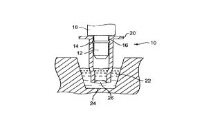
With reference to Figure 1 the reagent contact element 10 is shown
frictionally attached to a rod 12 of the parallel sequential bio-polymer
synthesis
apparatus. In one embodiment the rod may be equipped with a circumferential
protrusion 14. In this embodiment the reagent contact element 10 is equipped
with
a groove 16 adapted to frictionally engage the circumferential protrusion 14
so as
to ensure a positive attachment to the rod 12. Optionally, the rod 12 may be
equipped with an ejection sleeve 18 so as to facilitate the automatic removal
of the
reagent contact elements at the end of the synthesis reaction.
The reagent contact elements may be equipped with a flange 20. When the
ejection sleeve 18 is activated it pushes against flange 20 so as to disengage
the
reagent contact element from the rod. In addition, flange 20 serves to retain
the
reagent contact element in a tray when the reagent contact elements are
dispensed
in a tray. Figure 1 shows the reagent contact element submerged in a reagent
solution 22 that is conveyed in trough 24. In the embodiment shown, the
reagent
contact element comprises a porous vessel 26 containing solid support resin
and the
porous vessel 26 is submerged in the reagent mixture 22.
With reference to Figure 2, an alternative embodiment is shown wherein
reagent contact element 10 is provided with two porous membranes 28 between
which solid support 30 is trapped.
Figure 3 shows an embodiment of reagent contact element 10 wherein a filter
element 32 is inserted into reagent contact element 10 so as to define a
cavity in the
distal portion of reagent contact element 10. The filter element 32
frictionaliy
engages the side walls of reagent contact element 10 so as to maintain its
position
relative to the distal end of the reagent contact element 10. The cavity
defined by
the filter element and the side walls of reagent contact element 10 is then
filled with
solid support 30 and the end closed off with membrane 28.
_g_
r
CA 02279232 1999-04-O1
WO 98!14271 PCT/US97/17531
Figure 4 shows an alternative embodiment wherein filter element 34 is
molded from the side walls of reagent contact element 10 and forms an integral
part
of the reagent contact element. The molded filter element 34 defines a cavity
at the
distal portion of reagent contact element 10. The cavity is then filled with
solid
support 30 and closed off with membrane 28.
Figure 5 shows an alternative embodiment of the present invention wherein
the most distal portion of reagent contact element 10 has been modified so as
to
permit the attachment of a hanging porous vessel 36. Solid support material is
enclosed within the hanging porous vessel. The hanging porous vessel 36 may be
fabricated of any suitable material i.e., one that is nonreactive with the
reagents
used in the synthetic process and has a low water absorption as well as the
requisite
strength.
Figure 6 shows an embodiment of the invention wherein the most distal
portion of reagent contact element 10 has been equipped with one or more slots
38.
The slots 38 promote entrance of the reagents into the reagent contact element
and
facilitate drainage of the reagents from the reagent contact element. One
skilled in
the art will appreciate that the slots 38 may be incorporated into any other
embodiment of the instant invention. Figure 6 shows an embodiment of the
invention wherein a porous vessel defined by two porous sheets 28 enclose
solid
support material 30.
Figure 7 shows an embodiment of the invention wherein the proximal portion
of the reagent contact element 10 has been modified so as to incorporate axial
and
radial locating features. In the embodiment shown, the reagent contact element
10
has been modified to define a slot 40 which engages a pin 42 on rod 12. Other
methods of insuring the accurate placement of the reagent contact element on
the
rod are known to those skilled in the art and are seen to be within the scope
of the
present invention.
The reagent contact elements of the present invention can be manufactured
by making up separate porous vessels then attaching the porous vessels to the
inert
portion of the reagent contact elements. The fabrication of the inert portion
of the
reagent contact element is within the skill of the ordinary practitioner in
the art.
The porous vessels may be attached by gluing, heat welding or ultrasonic
welding
_g_
CA 02279232 1999-04-O1
WO 98114271 PCTIUS97/17531
to the reagent contact element. In preferred embodiments, the porous vessels
are
ultrasonically welded to the reagent contact element.
The porous vessels may be made by forming a well or indentation in a sheet
of porous material then filling the well with solid support material and then
sealing
the top of the well with a second piece of porous material. Alternatively,
solid
support material may be trapped between two flat sheets of porous material.
One
skilled in the art will readily appreciate that these two methods will provide
for the
incorporation of various amounts of solid support material thereby permitting
adjustment of the scale of the reaction to suit individual synthetic
applications. The
porous vessels will be designed so as to maximize the amount of the reaction
sites
at the lower end of the reagent contact element to minimize the reagent usage
in the
trough. For example, in the embodiment of Figure 5, the hanging bag may be
configured so as to trap the majority of the solid support material at the
most distal
portion of the bag. This can be accomplished by creating a seal 44 at some
point
along the length of the bag so as to trap the material into the distal
portion.
The reagent contact elements are constructed of a size to fit into ninety-six
well microtiter plates while in an array in a tray. This permits placing
reagent into
a microtiter plate and dipping the array of reagent contact elements into the
reagents. This will be useful for the simultaneous cleavage of completed
polymers
from the solid support and transfer of the polymer into a microtiter plate for
subsequent screening. For example, in the case of an oligonucleotide, the
wells of
the microtiter plate may be filled with a cleavage reagent and the reagent
contact
elements may be placed in a tray and dipped into the reagent.
The reagent contact elements are designed so as to interface firmly in a
frictional fit with the rods 12. For example, the reagent contact elements may
be
configured with a groove 16 and the rods with a circumferential protrusion 14
designed so as to engage the groove as shown in Figure 1. Alternatively, the
rod
and the interior of the reagent contact element may be manufactured with
complimentary tapers so that the reagent contact element may be slid onto the
end
of the rod and firmly engage the rod.
The reagent contact elements of the present invention may be distributed in
trays. The trays may be both color coded for easy identification by users and
have
-10-
CA 02279232 1999-04-O1
WO 98/14271 PCT/US97/17531
a unique feature such as a whole or bar code, etc. for automatic
identification by the
instrument. The trays will be designed such that the reagent contact elements
may
be made color coded for different starting seed molecules that are attached at
the
end of the reagent contact element. The reagent contact elements may be made
of
translucent material for better view of the reagents used during the synthetic
process. The reagent contact element is of such shape and length so as to
bring the
solid support into appropriate position in a trough or microtiter plate. The
reagent
contact element is equipped with axial and radial locating features which
interface
to the rod for precise reagent contact element positioning. These features may
be
slots or grooves in the reagent contact element and corresponding pins or
protrusions in the rod.
This invention has been described in terms of specific embodiments set
forth in detail, but it should be understood that these are by way of
illustration only
and that the invention is not limited to the specifically recited embodiments.
Modifications and alterations will be readily apparent to those skilled in the
art and
these modifications and alterations are within the scope of the invention.
Accordingly, these modifications and alterations of the disclosed invention
are
considered to be within the scope of the invention.
-11-