Note: Descriptions are shown in the official language in which they were submitted.
CA 02286009 2001-10-17
_1-
OPTICAL INSTRUMENT HAVING A VARIABLE OPTICAL FILTER
STATEMENT AS TO FEDERALLY SPONSORED RESEARCH
The U.S. Government has certain rights in this invention pursuant to a Grant
awarded by
the National Institutes of Health.
BACKGROUND OF THE INVENTION
2. Field of the Invention
This invention relates to optical instruments for observing an image of an
object.
3. Description of Related Art
Imaging spectroscopy allows a user to observe and record the spectral
characteristics of
an illuminated object throughout the spatial extent of the object. Observing
optical
characteristics of an object across a wide range of wavelengths allows the
user to glean
information about the object, including in many cases its material
composition.
For example, fluorescent excitation characteristics are derived by
illuminating an object
at several wavelengths and, for each of these wavelengths, observing the
object's
fluorescent emission at a specified emission wavelength. Fluorescent emission
characteristics are derived by illuminating the object at a selected
excitation wavelength
and observing the wavelengths at which the object fluoresces in response to
the
illumination. Reflection, absorption, and other spectral characteristics are
derived with
similar techniques, in known fashion.
A conventional imaging spectroscope typically includes an optical cube
consisting of an
excitation filter, an emission filter, and a dichroic mirror. The excitation
filter is a band
pass or high pass filter that allows only short wavelength light from a light
source to pass
through. The emission filter is a band pass or low pass filter that passes
only long
wavelength light emitted by the object in response to illumination by the
shorter
CA 02286009 2001-10-17
-2-
wavelength exciting light. The dichroic mirror is a beam sputter that reflects
the exciting
light onto the object and then allows emitted light from the object to pass
through. The
"cut on" wavelength of the dichroic mirror generally lies between the
transmission bands
of the excitation and emission filters in a simple configuration.
Instead of optical cubes, some spectroscopes employ variable optical filters
to acquire
optical spectra. The band pass characteristics of a variable filter may be
changed by
altering the physical orientation or optical characteristics of the filter.
For example, U.S.
Patent 3,864,037 to Johnson. describes an
imaging spectroscope having a variable filter placed among the elements of the
instrument's objective lens. U.S. Patent 3,963,350 to Watanabe.
describes an optical instrument for imaging blood samples
where a source light passes through a variable filter before illuminating the
blood sample.
CA 02286009 1999-10-04
WO 98/45687 PCT/US98/06654
-3-
SUMMARY OF THE INVENTION
The invention comprises an optical instrument for use in collecting light from
an object,
the optical instrument having a post-objective waist with a variable optical
filter
positioned approximately at the post-objective waist. The invention also
comprises an
optical instrument for collecting light from an object, comprising an
objective lens
positioned to receive light from the object, an exit lens positioned to focus
the light at a
focal position, and a variable optical filter positioned between the objective
lens and the
focal position approximately at a waist of the light.
The optical instrument may be an epifluorescence microscope for use in
observing an
image formed from Iight from an object under illumination by a light source.
The light
source may be, for example, a filtered light source or a monochromatic light
source,
preferably in an epifluorescence configuration. The variable optical filter
may be a
circular variable interference filter or a tilting interference filter. In
some embodiments,
the orientation of the filter may be varied (e.g., by a mechanism such as a
stepping
motor) to block light outside of one band at one time and outside of another
band at
another time. The variable filter preferably is band pass, blocking
substantially all light
at wavelengths other than a selected wavelength band.
In some embodiments, the optical instrument includes a recorder, such as a CCD
camera,
placed at the focal position to record an image of the light from the object.
The recorder
also may be connected to a computer system, which may store and process the
recorded
images.
Advantages of the invention may include one or more of the following:
~ At a waist of the instnunent, the area of the light passing through the
variable
filter is very small, so the light spans only a small portion of the filter,
improving out-of band filter leakage with less likelihood of image distortion;
SUBSTITUTE SHEET (RULE 26)
CA 02286009 1999-10-04
WO 98/45687 PCT/US98/06654
-4-
~ The waist of the light is readily accessible, permitting existing
instruments to
be modified in conformance with the invention.
The details of one or more embodiments of the invention are set forth in the
accompany-
ing drawings and the description below.
SUBSTITUTE SHEET (RULE 26)
CA 02286009 1999-10-04
WO 98/45687 i'CTIUS98/06654
-5-
BRIEF DESCRIPTION OF THE DRAWINGS
FIGURE I is a schematic diagram of an optical instrument, such as an
epifluorescence
microscope, having a variable optical filter placed at a light waist in the
instrument.
FIGURES 2a and 2b are a front view and a side view, respectively, of variable
filters that
may be used in the instrument of FIGURE I .
Like reference numbers and designations in the various drawings indicate like
elements.
SUBSTITUTE SHEET (RULE 26)
CA 02286009 1999-10-04
WO 98/45687 PCT/US98/06654
-6-
DETAILED DESCRIPTION OF THE INVENTION
Overview
For purposes of illustration only, the invention will be described in the
context of an
epifluorescence microscope. However, while the invention is well suited for
use with an
epifluorescence microscope, it also may be used in other optical instruments,
such as
telescopes, in which only certain wavelengths of light are to be observed
and/or recorded,
or in non-focusing applications, in which only certain wavelengths of Iight
are to be
collected but without regard to forming an image.
Fluorescence microscopy is based on the same principles of optics as light
microscopy.
To create an image in a light microscope, light waves from an illumination
source pass
through and around an object or specimen. .Those light waves are gathered and
then
recombined by the objective lens system of the microscope to form the image of
the
object. In the case of epifluorescence microscopy, a single lens serves as
both the
condenser {the lens system that focuses the light before it reaches the
specimen) and the
objective. Selected wavelengths of light pass through the lens and excite
fluorescent
molecules (e.g., from a staining dye) in an object. The excited molecules re-
emit light at
a longer wavelength (a different color). Some of that Iight is collected by
the objective
lens and then optically coupled to a detection system to produce a fluorescent
image.
Achieving a fluorescence image is optically demanding, because the low-energy
light
emitted from a fluorescing object is generally not as intense as the high-
energy
wavelengths initially used to excite the fluorescent molecules. Accordingly,
the optical
system of a fluorescence microscope incorporates one or more filters that fine-
tune the
light going to and coming from an object. The present invention provides a
novel
configuration for a variable filter system in such an optical instrument.
SUBSTITUTE SHEET (RULE 26)
..., T... ~ ..
CA 02286009 1999-10-04
WO 98/45687 PCT/US98/06654
Exemplary Microscope
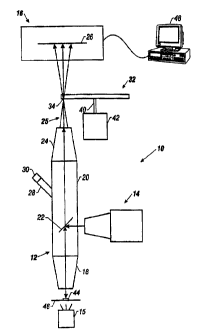
Referring to FIGURE 1, an imaging spectroscope 10 utilizing the present
invention
combines the spatial resolution of a conventional epifluorescence microscope
(less than
about one micron) with the spectral resolution of a conventional fluorimeter
(less than
about 2 nm}. The illustrated spectroscope 10 includes a microscope 12 combined
with
an epifluorescence light source 14 and an image recorder 16, such as a CCD
imaging
camera. The microscope 12 includes an objective lens 18 in the light path 25
from an
object 44. Within the body 20 of the microscope 12, a dichroic mirror 22
directs light in
a first band of wavelengths from the epifluorescence light source 14 to the
object 44
through the objective lens 18, and passes light in a second band of
wavelengths from the
objective lens 18. A projection eyepiece exit lens 24 focuses the light in the
light path 25
at a focal position 26. However, in some applications, the exit lens 24 can be
a non
imaging optical collector, such as a compound parabolic concentrator having
high
interior reflectance. As is known in the art, both the objective lens 18 and
the exit lens
24 may be complex lens structures.
The microscope 12 also may include an ocular port 28 and an ocular lens 30
that allow
a user to view images directly when the image recorder 16 is in place, in
known fashion.
One suitable instrument that may be adapted for use with the invention is the
BX60
epifluorescence microscope available from Olympus America.
In the illustrated embodiment, a CCD array of the CCD camera 16 is placed at
the focal
position 26 to record images formed from the light in the light path 25. One
suitable CCD
camera is the K7 CCD camera (16 bit, 760 x 510 resolution) available from
KAIROS
Scientific Inc. of Santa Clara, California.
An important aspect of the invention is the placement of a variable optical
filter 32
approximately at a post-objective optical waist 34 in the light path between
the objective
lens 18 and the focal position 26. In a complex optical instrument, more than
one such
waist 34 may exist; in the embodiment shown, one such waist 34 is between the
SUBSTITUTE SHEET (RULE 26)
CA 02286009 1999-10-04
WO 98/45687 PCT/US98I06654
_g_
projection exit lens 24 and the focal position 26. The variable filter 32 is
positioned
directly within the light path 25 approximately at the waist 34. The cross-
section of the
light path 25 at the narrowest waist 34 approximates a point, and the light in
the light
path 25 is nearly collimated. For certain types of filters (e.g., a circular
variable
interference filter), broader band pass characteristics (i.e., more light and
less spectral
differentiation) can be obtained by moving the variable filter 32 slightly off
the narrowest
waist 34 along the z-axis. However, the cross-sectional area of the light
should extend
over only the narrowest filter band of a particular variable filter 32;
typically this range
is within about ~5 millimeters from the narrowest waist 34 along the light
path 25.
To reduce glare and reflections, the variable filter 32 preferably is tilted
slightly (about
5 degrees) with respect to the z-axis of the microscope 12. The exact angle
does not seem
to be critical and is a matter of design choice.
In the illustrated embodiment, the variable filter 32 connects to the axle 40
of a stepper
motor 42, which is used to rotate the filter and thus vary its filtering
characteristics, as
described in more detail below. However, other mechanisms may be used to vary
any
particular type of variable filter 32. Preferably, any such mechanism is
suitable for
automated control.
The epifluorescence light source 14 may be a laser, a monochromator with a
xenon arc
lamp, or any other suitable source with suitable filtering. A variable
wavelength source
has a number of advantages. By replacing the fixed wavelength excitation and
emission
filters of a conventional epifluorescence microscope with fully tunable
wavelength
selection, the invention enables simultaneous determination of the
fluorescence spectrum
of every pixel in a scene.
Operation
The illustrated image spectroscope 10 may be used to observe and record the
absorption,
fluorescent excitation, and fluorescent emission characteristics of an object
44, such as
SUBSTITUTE SHEET (RULE 26)
~ .
' CA 02286009 1999-10-04
WO 98/45687 PCT/US98/06654
-9-
a bacterial sample or a plant specimen, mounted on a stage 46. The
epifluorescence light
source 14 generates a selected short wavelength excitation light that is
reflected by the
dichroic mirror 22 through the objective lens 18 (acting as a condenser) and
onto the
object 44. If the excitation light causes the object 44 to fluoresce, light
emitted by the
object 44 travels through the objective lens 18 and encounters the dichroic
mirror 22.
Thus, the variable filter 32 must be positioned on the post-objective side of
the objective
lens 18 to properly filter desired wavelengths.
The dichroic mirror 22 preferably is a long-pass filter (i.e., a long
wavelength filter), so
that only long wavelength light emitted by the object 44 passes through to the
exit lens
24. The exit lens 24 then focuses the emitted light onto the CCD array of the
CCD
camera 16, which records the images contained in the light. The CCD camera 16
may
pass the images to a computer system 48 for processing and storage.
For collection of fluorescent information, the dichroic minor 22 should
efficiently reflect
(towards the sample object 44) wavelengths shorter than the emission
wavelength being
observed, and efficiently pass (towards the image recorder 16) wavelengths
longer than
the excitation wavelength. This "cut-on" wavelength occurs in the region
between the
fluorescent excitation and emission bands where overlap is minimal. To further
optimize
the amount of information which can be collected in an emission scan, the cut-
on
wavelength of the dichroic mirror 22 should be positioned immediately to the
red side
of the excitation band. For an excitation scan, the cut-on transmission
wavelength.of the
dichroic mirror 22 should be positioned immediately to the blue side of the
emission
band. The microscope 12 may include multiple dichroic mirrors with different
cut-on
points, as well as a mechanism to exchange the minors automatically. The
epifluore-
scence Iight source 14 preferably projects light in a direction orthogonal to
the axis of
transmission of the microscope 12, so the dichroic minor 22 should be
positioned at 45 °
with respect to the transmission axis of the microscope 12. In the preferred
embodiment,
the dichroic mirror 22 is mounted in a conventional optical cube from which
the
conventional excitation and/or emission filter has been removed.
SUBSTITUTE SHEET (RULE 26)
CA 02286009 1999-10-04
WO 98/45687 PCT/US98/06654
- 10-
In an excitation scan mode, the excitation wavelength of the light source 14
is varied
while images of emissions are recorded through one band of wavelength
filtration. Such
scans can be repeated for a set of emission filter wavelength bands. In an
emission scan
mode, the excitation wavelength of the light source 14 is set on one band of
wavelength
filtration while images of emissions are recorded through a series of
filtration band
wavelengths. Such scans can be repeated for a set of excitation filter
wavelength bands.
The computer system 48 is preferably used to control the variance of the
excitation
wavelength and the emission filtration wavelength.
The spectroscope 10 also may include a second light source 15, such as a white
or
monochromatic light source, to illuminate the object 44 in a bright field
mode. The
second light source 15 may also be configured as shown in U.S. Patent
3,963,350 with
a variable optical filter. Use of the lower second light source I5 facilitates
image
processing and imaging spectroscopy for combining bright field and
epifluorescence data
while using the same type of imaging spectroscope 10 setup shown in FIGURE I .
In an absorption mode, white light from the louver second light source 15 is
used to "back
Light" the sample object 44. Wavelength selection is accomplished by rotation
of the
variable f lter 32, with the dichroic mirror 22 preferably removed. In an
alternative
embodiment, absorption images may be collected by filtering or tuning the
second light
source 15 and removing both the dichroic mirror 22 and the variable filter 32,
or
providing a clear region in the variable filter 32.
Variable Filter
Referring to FIGURES 2a and 2b, the variable filter 32 may be one of several
types of
filters. FIGURE 2a shows a circular variable interference filter (CVIF) 60, or
wedge
filter, the band pass characteristics of which vary angularly. A typical CVIF
is formed
from a circular plate of glass, the surface of which is coated with an optical
interference
film. The thickness of the interference film determines the band pass
characteristics of
the filter, so the thickness of the film layer in a CVIF varies angulariy
around the
SUBSTITUTE SHEET (RULE 26j
,.
CA 02286009 1999-10-04
WO 98/45687 PCT/US98/06654
circumference ofthe filter to give the filter variable band pass
characteristics. In a CVIF,
the thinnest portion of the film layer is associated with shorter wavelength
selection and
the thickest portion of the film layer is associated with longer wavelength
selection. The
preferred filter has a 400-720 nm filtering range.
One advantage of a CVIF filter is that it is manufactured in a continuous
process on a
single flat glass substrate, and thus exhibits low distortion and accurate
matching of all
relevant optical parameters. Other advantages of a CVIF filter include the
following:
1 ) Robustness. Compared to alternative technologies, a CVIF is relative
insensitive to temperature and light acceptance angles.
2) Excellent image registration. In one prototype of the invention, no spatial
translation in the x or y dimensions or warping in some complex manner
occurred as the CVIF variable filter 32 was turned. It appears that placement
of refractive and dielectric materials approximately at a waist 34 does not
cause problems that are known to occur in placement of filters at other
positions in the optics of such an instrument.
3) CVIF data are parfocal with the eye. In one prototype of the invention,
placing the CVIF variable filter 32 in the optical path of the instrument did
not change the focal position 26 for the CCD camera 16. In other words, the
optical focus through air (no CVIF variable filter 32) was the same as with
the CVIF variable filter 32. Operationally, this means that the exact focus
detemlined by using one's eyes on the ocular lens 30 is exactly what the CCD
camera 16 "sees" to be in focus. Thus, it appears that eyes and the CCD
camera 16 are parfocal with and without the CVIF at all relevant magnifica
tions. Thus, no "electronic" focusing is needed while observing the image
generated by the CCD camera 16.
4) Low cost. A CVIF variable filter 32 is relatively inexpensive and
manufactur
ing specifications are flexible compared to other variable filters.
SUBSTITUTE SHEET (RULE 26)
CA 02286009 1999-10-04
WO 98/45687 PCT/US98/06654
-12-
5) CVIFdata is easily calibrated. The percentage transmission (%T) of a CVIF
variable filter is rather constant and any changes vary in a slow monotonic
manner around the filter. Therefore, there are no sudden "glitches" in %T
which would affect throughput and radiometric calibration in an abrupt
manner, as is often the case using conventional blocking filters.
The wavelengths of emitted light observed in a typical spectroscopy
application vary
from 400 nm to 720 nm. However, a greater range of wavelength selection often
is
desired. In the particular CVIF 60 illustrated in FIGURE 2a, the wavelength
selection at
any given angular position is determined by the equation ~. _ (540 - 28) nm
for angles
between -160° and 160°. Suitable CVIF filters are available from
Optical Coating
Laboratories, Inc. of Santa Rosa, California.
FIGURE 2a also illustrates one benefit of placing the CVIF 60 at a waist of
the light path
25. Circle 50 represents the cross-section of the light path 25 striking the
surface of the
variable filter 32 near the waist 34, while circle 52 represents the cross-
section further
away from the waist 34. Because circle 50 is significantly smaller than circle
52, the light
represented by circle 50 encounters a smaller angular percentage of the
variable filter 32
than does the light represented by circle 52. Therefore, the band pass
characteristics of
the variable filter 32 are narrower with respect to circle 50 than they are
with respect to
circle 52 (i.e., fewer undesired wavelengths leak through the filter for
circle 50 than for
circle 52). If the cross-section of the light at the surface of the variable
filter 32 were
reduced to a point (i.e., the narrowest waist), the filter would pass
essentially only the
narrowest band of wavelengths permitted by the particular filter design.
The periphery of a CVIF 60 has less of a wavelength "ramp" or gradient
compared to
inner diameters, and thus is the preferred region to be positioned within a
waist, since the
size of the waist can be larger while maintaining the narrowest band pass. As
discussed
above, an image spectroscope having a CVIF 60 placed approximately at the
narrowest
waist can be made to operate with a band pass of less than 2 nm.
SUBSTITUTE SHEET (RULE 26)
CA 02286009 1999-10-04
WO 98/45687 PCT/US98106654
-13-
While the variable filter 32 is shown as circular, similar technology can be
used to create
linear or other shaped "wedge" interference filter that can be moved across
the waist 34
of an imaging spectroscope 10.
FIGURE 2b shows a tilting interference filter 62, which may be used instead of
a CVIF
in the image spectroscope. The band pass characteristics of the tilting
interference filter
62 are varied by tilting, or rotating, the filter about axis 54 to vary the
effective thickness
of the filter with respect to the incident light. Line 56 represents the
thickness of the filter
62 with respect to the center of the light path 25 when the filter 62 is fully
upright. Line
58 represents the thickness of the filter with respect to the center of the
light path 25
when filter 62 is tilted to angle A. Because line 58 forms the hypotenuse of a
right
triangle for which line 56 is one of the legs, it is clear that the effective
thickness of the
filter is greater when the filter is tilted. The use of a tilting interference
filter in an image
spectroscope is described in detail in U.S. Patent 3,864,037.
Instead of a CVIF or tilting interference filter, the variable filter 32 may
be one of any
number of variable filter types, including: acousto-optical tunable filters;
electro-
polarization devices, such as liquid crystal tunable filters; glass gradient
filters; and
multiple independent filter films or glasses arrayed on a linear, circular, or
other shaped
holder or substrate.
A number of embodiments of the present invention have been described.
Nevertheless,
it will be understood that various modifications may be made without departing
from the
spirit and scope of the invention. For example, the variable filter 32 can be
band pass,
multi-band pass, high pass, or low pass. In various embodiments, the light in
the light
path 25 may represent spectra of various types, including (but not limited to)
reflectance
spectra, emission spectra of various types (e.g., chemiluminescence,
phosphorescence,
and/or fluorescence), light from elastic scattering effects (e.g., Rayleigh or
Mie
scattering) or inelastic scattering effects (e.g., Raman scattering), and
absorption spectra.
In addition, the imaging spectroscope can be configured for different modes,
such as
SUBSTITUTE SHEET (RULE 26)
CA 02286009 1999-10-04
WO 9814568'7 PCT/US98/06654
-14-
bright field, dark field, phase contrast, and other known modes. Further, in
certain
configurations, the light source 14 is not needed (e.g., when obtaining
chemilumine-
scence spectra) or is fumed of~at times while observing a specimen (e.g., when
obtaining
phosphorescence spectra). Accordingly, it is to be understood that the
invention is not
to be limited by the specific illustrated embodiments, but only by the scope
of the
appended claims.
SUBSTITUTE SHEET (RULE 26)
,.