Note: Descriptions are shown in the official language in which they were submitted.
CA 02288389 2009-05-29
ROTARY SEAL WITH RELIEF ANGLE FOR CONTROLLED TIPPING
BACKGROUND OF THE INVENTION
1. Field of the invention.
The present invention relates to an improved rotary
seal and energizer with pressure balancing and improved
lubrication properties.
2. Description of the related art.
Prior seals have limitations when given an applied
pressure and relative velocity, i.e., when a sealed rod is
rotated. In operation, typical pressure applications occur
at 3000 PSI and above, and fairly low surface velocity
movement of 10 to 50 feet per minute.
Due to the rotary motion and poor lubrication, the
constant friction can lead to heat generation increases,
thereby accelerating wear and causing seal extrusion and
loss of
material. During seal pressurization, the seal slides over
in the groove and the energizer forms up in a corner
creating a heavy load, resulting in high friction. This high
friction
accelerates heat generation, compression set, and possible
loss of seal ring energization, which may also result in the
creation of an undesirable dynamic interface created between
the energizer
1
CA 02288389 2009-05-29
and seal ring, thus producing undesirable abrasion and wear
to the energizer.
SUMMARY OF THE INVENTION
To improve those situations, the present invention
includes a pressure balance design which reduces overall
friction during operation and improves the lubrication
underneath the seal ring. Preliminary results indicate a
reduction of torque of over fifty percent. Heat generation
is also reduced by nearly fifty percent and an improved
leakage control is also evident.
The seal ring of the present invention includes a lower
center groove. The center groove is in the contact space
between the seal ring and rod. The groove minimizes the
bottom contact area, thus increasing the contact stresses
and improving leakage control. When the system is
pressurized, the seal ring pivots about a point on the
bottom surface contact areal thereby providing a pressurized
seal contact along a larger bottom contact area, while
maintaining an extrusion resistant chamfer.
In a broad aspect, the present invention relates to a
seal for sealing a gap between a first member and a second
member moving relative to the first member, said seal
comprising: a ring having a cross section with a pivot point
in response to external pressure, and a surface adjacent the
pivot point, the surface engaging the second member when the
seal is subjected to external pressure.
In another broad aspect, the present invention relates
to a seal arrangement for sealing a gap between a first
member and a second member, said second member moving
relative to said first member, said seal arrangement
2
CA 02288389 2009-05-29
comprising: a first ring having a cross section with a
perimeter, a pivot point and a surface adjacent the pivot
point, said first ring pivoting about said pivot point and
said surface adjacent the pivot point engaging the second
member when external pressure is applied to said seal
arrangement; and a second ring having a cross section with a
perimeter.
In another broad aspect, the present invention relates
to a seal for sealing a gap between a first member and a
second member moving relative to each other, said seal
comprising: a ring having a first surface and a second
surface, said second surface engaging with the second member
when said seal is subjected to external forces, and said
second surface disengaging from the second member when said
seal is not subjected to external forces; wherein said the
ring has a cross-section with a perimeter having a pivot
point and the first and second surfaces, the ring being
configured for pivoting about the pivot point when the ring
is subjected to external forces, the second surface being
adjacent the pivot point.
In another broad aspect, the present invention relates
to a method of sealing a gap between a first member and a
second member, said second member moving relative to said
first member, comprising the step of providing a ring
capable of pivoting about a cross sectional point when
subjected to external pressure wherein the ring further
includes a surface which engages the second member when the
seal is subjected to external pressure, the surface being
adjacent the pivot point.
In the invention, a seal for sealing a gap between a
first member and a second member moving relative to the
2a
CA 02288389 2009-05-29
first member comprises a ring with a cross section, the
cross section having a pivot point and a perimeter. When
external pressure is applied to the ring, for instance with
the addition of fluid pressure, the ring responds by
rotating about the pivot point.
2b
CA 02288389 1999-10-29
In another embodiment of the invention, a seal arrangement
is provided for sealing a gap between a first member and a second
member, the second member moving relative to the first member,
the seal arrangement comprising a first ring and a second ring.
In this embodiment, the first ring has a cross section with a
perimeter and a pivot point, the first ring pivoting about the
pivot point when external pressure is applied. Additionally, a
second ring is provided with a cross section and a perimeter.
In yet another embodiment of the invention, a seal for
sealing a gap between a first member and a second member moving
relative to the first member includes a ring having first surface
and a second surface, the second surface sealingly engaging with
the second member when the seal is subjected to external forces,
and the second surface disengaging with the second member when
the external forces are absent.
In a further embodiment of the invention, the seal
arrangement comprises a first ring having a cross section with a
perimeter, a first lip, a second lip, and a recess defined
between the first lip and the second lip. Additionally, a second
ring is provided and disposed between the first member and the
first ring, the second ring having a perimeter that protrudes
into the recess of the first ring during a pressurized state, and
spans the recess during a non-pressurized state.
3
CA 02288389 1999-10-29
In an alternative embodiment of the invention, a sealing
structure for sealing a gap between two machine parts arranged
for motion relative to each other comprises a sealing ring having
an inner surface facing the second machine part, the inner
surface having a pivot point, a first lip, a second lip, a recess
defined between the first and second lip, and an outer surface
facing toward the first machine part, the sealing ring pivoting
about the pivot point when exposed to external pressure.
Additionally, an energizer ring is provided having a cross
section with a perimeter, the energizer ring being disposed
between the outer surface and the first machine part.
Yet another embodiment of the invention can be described as
a method of sealing a gap between a first member and a second
member, the second member moving relative to the first member,
the method comprising the step of providing a ring capable of
pivoting about a cross sectional point when subjected to external
pressure.
The present invention is advantageous over the prior art
seals in that it provides a sealing surface that increases in
surface area as pressure against the seal escalates, while
providing a high contact pressure profile at the sealing apex to
improve leakage control. The increased sealing surface is
accomplished by the rotation of the seal-member during
4
CA 02288389 1999-10-29
pressurized states, thereby placing a larger part of the seal in
contact with a machine part when most needed.
It is a further advantage of the present invention that a
reduced sealing surface is provided during low pressure
operation. When the seal is in a low pressure state, and
rotation about a pivot point has not yet occurred, the present
invention advantageously provides a recess along its sealing
surface, thereby reducing the amount of friction between the
machine part and the seal.
It is yet another advantage of the present invention that a
tapered wall is provided on a side of the seal, the tapered wall
serving to firmly hold the seal in an ideal location against a
surface of the seal housing once the seal has rotated about the
pivot point.
It is a further advantage of the present invention that a
recess is provided on the top surface of the seal, for
interaction with an energizer ring. By providing a recess,
ridge, bump, or other means of increasing surface area and
simultaneously introducing localized high stresses, facing the
energizer ring, the edges of the seal's recess transmit deforming
pressure to the surface of the energizer ring during a
pressurized state, thereby greatly increasing the coefficient of
friction and/or the contact surface area, and consequently
5
CA 02288389 1999-10-29
substantially eliminating a dynamic interface between the
energizer ring and the seal.
BRIEF DESCRIPTION OF THE DRAWINGS
The above-mentioned and other features and advantages of
this invention, and the manner of attaining them, will become
more apparent and the invention will be better understood by
reference to the following description of an embodiment of the
invention taken in conjunction with the accompanying drawings,
wherein:
Fig. 1 is a fragmentary, sectional view on an axial plane
and illustrating one form of seal construction of this invention;
Fig. 2 is a fragmentary, sectional view of a prior art seal
configuration;
Fig. 3 is a fragmentary, sectional view of the seal element
of the present invention;
Fig. 4A shows an FEA graph of a Prior Art seal system,
installed in an unpressurized state;
Figs. 4B through 4D show FEA graphs of different embodiments
of the present invention, installed in an unpressurized state,
showing alternate energizers;
Fig. SA'shows an FEA graph of the embodiment shown in Fig.
4A under a high pressurization;
6
CA 02288389 1999-10-29
Figs. SB through 5D show FEA graphs of the embodiments shown
in Figs. 4B through 4D under a high pressurization;
Fig. 6 is a graph showing the results of a breakout torque
test comparing the prior art design to the design shown in Fig.
1;
Fig. 7 is a graph showing the results of a dynamic torque
test at low velocity comparing the prior art design to the design
shown in Fig. 1;
Fig. 8 is a fragmentary, sectional view on an axial plane
and illustrating one form of seal construction of this invention;
Figs. 9A through 9C are graphs showing the results of an
accumulated leakage test at high pressure comparing the prior art
design to the design shown in Fig. 1;
Figs. 10A and 10B are graphs showing the results of an
accumulated leakage test at medium pressure comparing the prior
art design to the design shown in Fig. 1;
Figs. 11A arid 11B are graphs showing the results of a wear
test at medium comparing the prior art design to the design shown
in Fig. 1; and
Figs. 12A through 12C are graphs showing the results of a
wear test at high pressure comparing the prior art design to the
design shown in Fig. 1.
7
CA 02288389 1999-10-29
Corresponding reference characters indicate corresponding
parts throughout the several views. The exemplification set out
herein illustrates one preferred embodiment of the invention, in
one form, and such exemplification is not to be construed as
limiting the scope of the invention in any manner.
DETAILED DESCRIPTION OF THE INVENTION
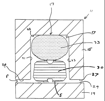
Referring now to the drawings and particularly to Fig. 1,
there is shown a construction which includes an annular seal
assembly 13, an outer member 15 having an annular seal groove or
gland 17 in which the seal assembly is mounted, 19. Fluid under
pressure is applied to the seal assembly 13 in the direction of
arrow P. The fluid passes through an annular clearance space 20
and acts directly on the seal assembly 13. It should be
understood that members 15 and 19 are merely illustrative of one
environment in which the seal assembly 13 can be advantageously
utilized. In the embodiment illustrated, the members 15 and 19
are mounted for relative rotational movement.
Although the outer member 15 could be of various different
configurations, in the embodiment illustrated, it includes
axially spaced, radially extending walls 21 and 23 interconnected
by an axial wall 25 to define the seal gland 17. The seal gland
17 completely circumscribes the inner member 19. In the
embodiment illustrated, seal gland 17 isgenerally rectangular in
8
CA 02288389 1999-10-29
an axial cross-section. The outer member 15 has a passage 27,
extending there through, in which the inner member 19 is
positioned.
The inner member 19 can be of various different
configurations; however, in the embodiment illustrated, it is in
the form of cylindrical shaft. The inner member 19 has the
cylindrical outer surface 29, which defines one of the surfaces
to be sealed.
The seal assembly 13 includes a seal element 30 and an
annular resilient elastomeric member which, in the embodiment
illustrated, is in the form of an o-ring elastomer 33. The
elastomer energizer can be utilized in nearly any common form, as
shown in Fig. 8. The seal element 30 can be constructed of any
of the materials commonly used for this purpose, for example, a
suitable plastic material such as thermoplastic may be used.
Polytetrafluoroethylene (PTFE), thermoplastic elastomer (TPE),
polyurethane (PU), and ultra high molecular weight polyethylene
(UHMWPE) are examples of thermoplastics that can be utilized. An
alternate embodiment of the system is shown in Fig. 8, having an
element 30 with a different top surface.
The construction of the seal element 30 can best be
understood with reference to Fig. 3, which shows the element
isolated by itself. Generally, the seal 30 is of an annular
9
CA 02288389 1999-10-29
configuration having a bottom surface A including a groove 34 for
low pressure sealing.
For ease of description, the outer peripheral surface of
seal element 30 will be described in relation to Fig. 3 in a
counter clockwise fashion describing the different angles, edges,
and surfaces. Starting from the lower left hand side, edge
points 1, 2, 3, 4, 4', 5, 6, and 7 generally outline the lower
bottom surface of surface element 30 while points 8, 9, 10, 11,
12, 13, 14, and 15 depict the changing contour on the top surface
T of seal element 30. Generally bottom surface A is located
between points 3 and 4, 4' and 5. This surface A is in contact
with inner member 19 during a non-pressurized state of the seal
assembly 13. Located between points 5 and 6 is a surface B,
which creates an increased pressurized contact area during seal
pressurization. Between points 6 and 7 is an extrusion resistant
chamfer. During pressurization, seal element 30 tilts or rotates
on point 5, bringing surface B into contact with member 19.
Between points 7 and 8 is a surface C, which is a relief
angle to allow seal element 30 to tip upon edge 5 during edge
seal pressurization. In the present invention, surface B and
surface C are most preferably perpendicular to one another. In
other preferred embodiments, an angle between surface B and
surface C may range from 85 to 95 , but more preferably from 89
CA 02288389 1999-10-29
to 91 . Between edges 8 and 9 and edges 14 and 15 are disposed
top chamfers that are provided to eliminate elastomer nibble.
One aspect of the invention, which is different from the
prior art, is the ability to balance pressure and frictional
aspects. During pressurization, the fluid pressure acts on the
area from point 1 through 5 of the seal element 30 balancing
against the pressure that is being generated through the
elastomer, so seal element 30 seals along the width from point 5
to point 6. At pressurization, all of the force that is
generating the torque is being driven only through point 5 to 6.
This tipping about point 5 is where torque reduction occurs.
This pressure balancing reduces the amount of load between the
seal and the rod. The radial loading is reduced by a proportion
of 1:7 to 5:7. To prevent extrusion, a chamfer is created
between points 6 and 7.
To help facilitate the tipping or the rolling action, seal
element 30 includes a back angle. This angle, or edge C is
perpendicular to edge B allowing the seal to roll in the groove.
Edge C will roll perpendicular to the rod and then also be
parallel with the gland wall 23 during pressurization. As the
elastomer 33 energizes across the top of seal element 30 it
attempts to increase the friction between the elastomer 33 and
the seal element 30, trying to keep the seal ring from not
11
CA 02288389 1999-10-29
spinning with member 19, but rather to keep it within the gland
17.
To eliminate a dynamic interface, a groove, ridge, bump, or
other mechanical interlock 40 is provided on the top surface, as
shown in Figs. 4B through 4D. The elastomer 33 deflects down
into groove 40 and points 11 and 12 experience high loads. There
is a high strain on the elastomer 33 in that area. There is
strain reduction between points 11 and 12. There is no seal
element to support the elastomer 33 in groove 40, so the
elastomer 30 deforms down in the groove creating a high stress
concentration at 11 and 12. This increases the frictional
properties and/or torque between the elastomer component 33 and
the seal ring component 30, thereby providing a non-slipping and
interlocking relationship between elastomer component 33 and seal
ring component 30. Other modes of generating the increased
friction are to increase the contact surface area between
elements 30 through 33. Such increase is accomplished by
changing the shape.
Elastomer 33 deflects as the seal element 30 is rolled over,
and a stress concentration is also created therein. From point
10 down to point 9 there is an angle or surface which operates as
a strain relief for the energizer. There is another such surface
from the front side points 13 to 14. These angles relieve the
12
CA 02288389 1999-10-29
elastomer as it is being energized. Any relief of the elastomer
there allows the elastomer 33 to absorb some of the energy from
the applied pressure. Energy from the applied pressure is also
absorbed with the deformation of elastomer component 33 into
groove 40 on the top surface and the chamber formed by the
chamfered edge disposed between points 8 and 9.
Figs. 4A through 5D show a finite element analysis of the
normal contact stresses on the present invention in contrast to a
prior art seal. Figs. 5B through 5D shows the advantageous
reduction of the contact area when the seal arrangement is
pressurized. The greater-than-50% reduction in the contact area
provides torque, heat generation, and frictional improvements
compared to the prior art seal products.
Figs. 6 through 12 show the advantages of the present
invention with results of finite element analysis comparing the
prior art seal to the present invention. The analysis was
conducted using a test gland with tested surface velocities over
the seal including low, medium, and high surface velocity, having
constant rotation, and being subjected to low, medium, or high
pressure for a duration of 200,000 cycles. The surface finish
was in the range of 0.1 to 0.2 m.
Fig. 6 displays the improved break-out torque results of the
present invention over the prior art. Fig. 7 shows the dynamic
13
CA 02288389 1999-10-29
torque improvements of the present invention over the prior art
at low velocity. Figs. 9A through 9C show accumulated leakage
comparisons between the present invention and the prior art at
high pressure. Figs. l0A and lOB shows accumulated leakage
comparisons between the present invention and the prior art at
medium pressure. Figs. ilA and 11B show wear result comparisons
between the present invention and the prior art at medium
pressure. Figs. 12A through 12C show wear result comparisons
between the present invention and the prior art at high pressure.
While this invention has been described as having a
preferred design, the present invention can be further modified
within the spirit and scope of this disclosure. This application
is therefore intended to cover any variations, uses, or
adaptations of the invention using its general principles.
Further, this application is intended to cover such departures
from the present disclosure as come within known or customary
practice in the art to which this invention pertains and which
fall within the limits of the appended claims.
14