Note: Descriptions are shown in the official language in which they were submitted.
CA 02289423 1999-11-12
BACKGROUND OF THE INVENTION
1. Field of the Invention
The present invention pertains to the field of diagnostic and therapeutic
medical devices
and procedures. More panic;ularly, the present invention relates to the field
of stabilization,
S imaging and procedure facilitating platforms for the female breast.
2. Description a~f the Related Art
Women aged 40 and over are recommended to undergo an annual screening
mammogram
to potentially identify a breast cancer in its most early stages of
development. By definition, these
women are asymptomatic and t:he lesions within their breasts, if any, are most
often non-palpable.
Most small breast cancers are, therefore, diagnosed by screening mammography.
To obtain an
acceptable mammographic image, the breast must be compressed and held immobile
between two
parallel plates. Compression i.s mandatory to obtain the required mammographic
views, as an
adequate mammogram cannot lbe obtained unless the breast is in compression.
Conventionally, a
computer calculates the x, y arnd z coordinates targeting the lesion and a
biopsy instrument is then
inserted within the compressed breast to biopsy the lesion.
Because of the required compression, the placement of the compression plates
on the
woman's breast determines the skin entry site for the procedure and,
therefore, the location of the
resulting scar. Indeed, the position of the breast in the compression device
dictates where the
incision is to be made. Conventionally, the scar is most always on the side of
the breast, whether
superior, lateral, inferior or medlial. The scar can range from about 5 mm in
length to an unsightly
3 cm if a large coring device is used.
Rueisss2 Page 2
CA 02289423 1999-11-12
Examples of such devices and methods include that disclosed in U.S. Patent
5,702,405
issued Dec. 30, 1997 to He;ywang-K.oebrunner. As described in this reference,
the breast is
compressed between two plates of a stereotactic attachment to a tomography
device. Through
holes are disposed in one of the two compression plates at an oblique angle
within a plane that is
substantially perpendicular to the plane of the plates, to allow a biopsy
needle to access the breast
through the side thereof. Similarly, U. S. patent 4,563,768 to Read et al.
discloses a
mammographic device utilizing two parallel plates to compress the breast. One
of the
compression plates functions as an X-ray film holder. A matrix of perforations
is disposed in one
the compression plates, allowing access to the side of the breast by a biopsy
needle or the like.
U.S. patent 4,691,333 uses similar breast compression and side access
technology. LaBash, in
U.S. patent 5,499,989 discloses yet another breast compression scheme, in
which the breast is
stabilized by compression, whereupon a guide spool is aligned over an opening
in one of the
plates. The guide spool guides a tubular punch or a biopsy needle through the
breast to the lesion
site, puncturing the side of the compressed breast.
These and other similar devices share a number of disadvantages. When the
lesion is
biopsied with the breast in compression, the cavity left after the biopsy
procedure expands as the
breast is uncompressed after the procedure. This expanded cavity can cause
unsightly
disfigurements, particularly when large; coring devices are used. It would be
advantageous,
therefore, to perform the biops~~ procedure on an uncompressed breast.
However, localization of
small breast lesions h$s comventionally required mammographic imaging.
Mammographic
imaging, in turn, requires that the breast remain compressed.
Ultrasound imaging is currently used with good results for specific
indications, but is
generally not used as a screening modality. Indeed, ultrasound is
conventionally used to gather
xUSCSSSZ Page 3
CA 02289423 1999-11-12
additional information about a suspicious area seen on mammography, or about a
palpable lesion.
Conventionally, it has been dil~cult to determine conclusively that a
suspicious area as seen by
ultrasound correlates exactly with that seen during the mammogram. In
addition, suspicious
microcalcifications seen by mammography are not readily visualized by
ultrasound imaging
techniques currently available. Therefore, ultrasound conventionally has been
of little help in
biopsying or excising small, non-palpable cancers or suspicious areas.
In instances where surlvace ultrasound is effective in localizing a lesion, a
manual biopsy
procedure may be carried oust under surface ultrasonic guidance. In such a
directed biopsy
procedure, the lesion within the breast is sonographically targeted and a fine
needle aspiration,
core biopsy or vacuum-assisted core biopsy procedure is carried out. In such a
procedure, the
breast is not compressed and a surface ultrasound transducer is typically used
to image the breast
and the site of interest therein. In surface ultrasound-guided biopsy, the
physician must manually
(i.e., by placing a hand on the lbre:ast) stabilize the breast as best as
possible, hold the ultrasound
probe, and perform the biopsy accurately enough to obtain tissue from the
lesion. Conventionally,
this procedure is carried out bar inserting the needle within the breast in an
orientation that is as
near parallel to the patient's chest wall as possible. The breast
stabilization, the operation of the
probe, as well as the actual needle biopsy must be carried out simultaneously,
all the while
maintaining the needle within the focal plane of the ultrasound probe. It is
difl~cult to have an
assistant help perform the procedure because if the ultrasound probe and/or
needle are not exactly
in line and are off by a fraction of a millimeter, then the needle cannot be
visualized on the
ultrasound monitor. Moreover, any mavement of the patient (e.g., coughing,
shifting) will also
cause the biopsy device and surlface ultrasound probe to misalign.
Rusisssz Page 4
CA 02289423 1999-11-12
Carrying out biopsy procedures on the uncompressed breast would alleviate the
disadvantages associated with compressing the breast. Importantly, such
procedures on the
uncompressed breast would be less painful, would allow more choices for the
entry site, would
reduce the size of the cavity J.eft after the excisional procedure and would
provide a means for
excising tissue from the breast in its natural state.
SUMMARY OF THE INVENTION
In accordance with the principles of the present invention, a breast
stabilization device for
imaging and invasive medical p~rocedurea comprises:
a shell configured to surround a portion of a breast when the breast rests on
a
substantially flat surface, the shell including a first opening allowing at
least a portion of a nipple-
areolar complex of the breast to protrude therethrough, and
a first and second flange extending from the shell, the first and second
flanges being
configured to substantially secure the shell to the flat surface.
The shell may further comprise a third flange to secure the shell to a
patient's chest wall.
A first adhesive layer may also be included on the first, second and/or third
flanges to secure the
shell to the flat surface and/or a patient's chest wall. The shell may have a
truncated generally
semi-conical shape and may surround that portion of the breast not resting on
the flat surface.
The shell may include a substantially rigid outer member and a relatively
softer inner member, the
softer inner member, in use, being in contact with a patient's breast. A
second adhesive layer may
be disposed on the relatively softer inner member of the shell. The
substantially rigid outer
member may include a suction ;port and the relatively softer inner member may
include a plurality
of through holes in fluid comrrmnication with the suction port, to allow a
patient's breast to be
euH~sss2 Page 5
CA 02289423 1999-11-12
drawn toward the inner member when fluid is drawn from the suction port. The
first opening may
have a generally semi-circular shape and may include a first lip configured to
allow at least one
instrument to be clamped thereto. The shell may further include one or more
second openings
exposing the surface of the breast therethrough. A second lip may surround
each second opening,
to allow one or more instruments to be clamped thereto. The shell may include
a plastic material.
The present invention may also be viewed as a method for imaging and biopsying
a lesion
in a breast, comprising the steps of
compressing the breast between a first and a second compression plate;
localizing the lesion using mammography;
calculating spatial coor~3inates of the lesion;
inserting a biopsy df;vice including an intra-tissue ultrasound transducer
into the
compressed breast and positioning the excisional device adjacent to the lesion
using said spatial
coordinates;
activating the intra-tissue ultrasound transducer and verifying correct
placement of the
biopsy device under ultrasonic ,guidance;
releasing the breast from compression by moving the first compression plate;
placing a breast stabili~:ation device over the breast and securing the breast
stabilization
device at least to the second compression plate, and
biopsying the lesion under ultrasonic guidance from the intra-tissue
transducer of the
excisional device.
The spatial coordinates may be calculated with respect to a peri-areolar
border of the
breast. The breast stabilization device may include an opening allowing at
least a portion of a
xustsss2 Page 6
CA 02289423 1999-11-12
nipple-areolar complex to protrude therethrough and the biopsy device may be
inserted near the
peri-areolar border of the compressed and stabilized breast. The biopsying
step may include a
step of excising the lesion frorr~ the breast. A step of expanding the breast
within the stabilization
device prior to the biopsying step may also be carried out. The breast
stabilization device may
include a suction port and an inner member configured to contact the breast
during use, the inner
member including a plurality of through holes in fluid communication with the
suction port, and
the expanding step may include the step of drawing fluid from the suction port
to cause the breast
to be drawn toward the inner member. The first plate may be an upper plate and
the second plate
may be a lower plate. The se<;uring step may include a clamping step to clamp
the stabilization
device to the second plate and/'or an adhesion step to cause the stabilization
device to adhere to
the second plate. The securing step may include the step of securing the
stabilization device to a
patient's chest wall.
The present invention is also a method of imaging an uncompressed breast,
comprising the
steps of
making an incision near a peri-areolar complex of the breast
inserting a device including an 'ultrasound transducer through the incision
and into the
breast;
activating the ultrasoundl transducer within the breast, and
imaging the breast using data returned from the ultrasound transducer on a
display device.
The frequency of the ultrasound transducer may be selected within the range of
about 7.5
MHz to about 20 MHz. A step. of compressing the breast prior to the inserting
step may also be
carried out. A step of placing a breast stabilization device over at least a
portion of the breast
Ruatsssz Page 7
CA 02289423 1999-11-12
prior to the activating step may be carried out. The breast stabilization
device may surround at
least a superior portion of the breast.
According to another embodiment, a medical breast stabilization device
according to the
present invention comprises:
an outer member confbrming generally to a shape of a superior portion of a
female breast,
the outer member including a suction port, and
an inner member joined to the outer member and defining an interstitial space
therebetween, the inner member being relatively softer than the outer member
and comprising a
plurality of through holes in fluid communication with the interstitial space
and the suction port,
the inner member being drawn in intimate contact with the patient's breast at
least when fluid such
as air or other gas is drawn from the suction port.
The outer and inner member may define an opening configured to allow at least
a nipple-
areolar complex of the breast to protnide therethrough. One or more flanges
may be included to
secure the stabilization device; to a flat surface and/or to the patient's
chest wall. One or more
windows may be disposed tlv-ough both the inner and outer members, the window
or windows
exposing a portion of the patie;nt's breast therethrough. An adhesive layer
may be disposed on the
underside of the inner member, thereby causing the underside of the inner
member to adhere to
the patient's breast when the device is in use. The device may be a single use
or multiple use
device.
Rvetsssz page g
CA 02289423 1999-11-12
BRIEF DESCRIPTION OF THE DRAWINGS
For a further understanding of the objects and advantages of the present
invention,
reference should be made to the following detailed description, taken in
conjunction with the
accompanying figures, in which:
Fig. 1 shows a perspective view of a breast stabilization device in use,
according to an
embodiment of the present invention.
Fig. 2 shows a perspective view of the underside of a breast stabilization
device, according
to an embodiment of the present invention.
Fig. 3 is a cross-section of a breast stabilization device according to an
embodiment of the
present invention shown in Fig. 1, taken along line AA'.
Fig. 4 is a side view of the breast stabilization device in use, according to
an embodiment
of the present invention, shovving an interventional device inserted in the
breast tissue.
Fig. 5 is a flow chart of a method of biopsying and/or excising a breast
lesion according to
an embodiment of the present: invention.
DESCRIP'~ION OF THE PREFERRED EMBODIMENTS
Scars along the border of the areola are much less noticeable than scars of
similar length
made in the side surface of the breast. The edge of the areolar complex is,
therefore, an ideal
point of entry into the breast, as compared with the side, top or bottom of
the breast. However,
conventional devices are designed to allow access to the interior of the
breast only from the side
of the breast and not from the areolar border. The present invention addresses
these problems
and facilitates access to the interior of a compressed and uncompressed breast
around the peri-
areolar complex.
Rusisss2 Page 9
CA 02289423 1999-11-12
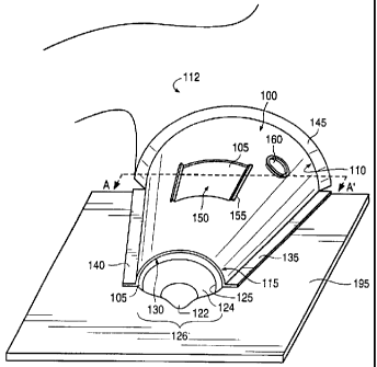
Fig. 1 shows an Embodiment of the breast stabilization device according to an
embodiment of the present iinvention. To better illustrate the functionality
thereof, the breast
stabilization device 100 showm in Fig. 1 is depicted in use, and secured to a
flat surface 195. The
flat surface 195, however, is shown for ease of description only and forms no
part of the present
invention. For example, the flat surface 195 may be a lower compression plate
of a
mammography imaging device (not shown). The breast stabilization device 100
has a shape that
conforms to the superior and lateral sides of a female breast 105. This shape
may, in general
terms, be characterized as a truncated semi-conical shape, although the
device's size and shape,
according to the present invention, may be adapted to fit various breast sizes
and shapes.
The breast stabilization device 100, according to the present invention,
generally conforms
to the size and shape of a female breast 105 as the breast 105 rests on a flat
surface 195, such as a
lower compression plate 195 of a mammography machine. Therefore, most of the
inferior portion
of the breast 1 OS shown in Fi;g. l lies substantially flat against the
surface 195. For purposes of the
present invention, the superior portion of the breast may be thought of that
portion of the breast
that is above a plane throuF;h the nipple and perpendicular to the chest wall
and the inferior
portion of the breast may be thought of that portion of the breast that lies
below that plane, when
the woman is in an upright position. Alternatively, the superior portion of
the breast may be
thought of as that portion of the breast that does not rest on the flat
surface 195, irrespective of
the position of the woman. The breast stabilization device 100 covers
substantially the entire
superior portion of the breast 105 as the breast 105 rests against the flat
surface 100 and may
cover some of the inferior portion thereof. The breast stabilization device
100 includes a proximal
end 110 and a distal end 115. The distal end 115 is disposed, in use, closest
to the nipple-areolar
complex 126 whereas the proximal end 110 of the breast stabilization device
100 is disposed, in
Rusisss2 Page 10
CA 02289423 1999-11-12
use, closest to the patient's chest 112. The distal end of the device 100 is
truncated, and includes
an opening 130 that is configured to allow, in use, at least a portion of the
nipple-areolar complex
to protrude therethrough. Indeed, as shown in Fig. 1, the nipple 122 and the
areola 124 protrude
from the opening 130 of the breast stabilizing device 100 according to the
present invention.
Moreover, the opening 130 naay allow a portion of the breast 105 that is
adjacent the peri-areolar
border 125 to be exposed therethrough.
The breast stabilization device 100 shown in Fig. 1 may also include a first
flange 135 and
a second flange 140. The first and second flanges 135, 140 may be disposed on
either side of the
breast stabilization device 100 and may extend parallel to the flat surface
195. The flanges 135
and 140 secure the breast stabilization device 100 to the flat surface 195.
For example, the first
and second flanges 135, 140 may include an adhesive layer on the side thereof
facing (in use) the
flat surface 195. Alternatively, the first and second flanges 135, 140 may be
clamped to the flat
surface 195 by any conventional clamping tool. Alternatively still, both an
adhesive layer on the
side of the flanges 135, 140 facing the flat surface 195 and clamping tools)
may be employed to
secure the breast stabilization device 100 to the flat surface 195. The
flanges 135, 140 may
extend all or a portion of the distance from the proximal end 110 of the
device 100 to the distal
end 115 thereof. The flanges 135, 140 may be continuous as shown in Fig. 1, or
may be
composed of a plurality of discrete elements facing the flat surface 195.
The breast stabilization device 100 may also include a third flange 145. The
third flange
145 may be disposed at or near the proximate end 110 of the breast
stabilization device 100 and
may secure the device 100 to the patient's chest wall 112. Preferably, the
side of the third flange
145 facing the patient's chest wall includes an adhesive layer to seal device
100 against the skin of
the patient's chest. Whereas the first and second flanges 135, 140 may include
relatively stiff
Rvsrsssz Page 11
CA 02289423 1999-11-12
material, such as a relatively hard plastic material for example, the third
flange 145 may be
relatively softer and include; a relatively soft plastic material. In this
manner, a good and
substantially fluid (e.g., air)-tight seal may be formed between the proximal
end 110 of the device
100 and the patient's chest wall 112.
The breast stabilizing device 100 may include one or more windows 150 (one
such
window 150 being shown i~,n Fig. 1 ) exposing the breast 105 therethrough. The
window or
windows 150 may include one or more lips 155. The lip or lips 155 may serve as
a platform on
which to attach or clamp, for example, instruments such as imaging devices and
the like. Indeed,
surface ultrasound may be carried out through the window or windows 150 during
an imaging
and/or interventional procedure and the surface ultrasound device (not shown)
may be secured to
the lip or lips 155 of the window or windows 150. The lip or lips 155 may be
integral to the
window or windows 160 or nnay be removable therefrom. If removable, the lip or
lips 155 may be
friction-fitted to the shell of the breast stabilization device 100, in the
manner discussed in detail
with reference to Fig. 3 below. A suction port or ports 160 may also be
disposed within the
breast stabilization device 100. A syringe or other vacuum-inducing device may
be attached,
clamped or otherwise removably affixed to the suction port or ports 160 to
create a partial
vacuum within the breast sta~~ilization device 100, in the manner disclosed
relative to Fig. 2.
Fig. 2 shows the bre;ist stabilization device 100 in an orientation wherein
the underside
230 of the device 100 is visible, the underside being that side of the device
100 that comes into
contact with the patient's skin (breast;) during use. As discussed with
reference to Fig. 1, a layer
of adhesive 210 may be disposed on each of the first, second and third flanges
135, 140 and 145,
respectively. The adhesive 210 disposed on the third flange 145 may be
different than the
adhesive 210 disposed on the flanges 135 and 140, as the adhesive 210 disposed
on the third
Rusisss2 Page 12
CA 02289423 1999-11-12
flange 145 contacts the patient's skin. A smooth sealing surface 220 may
surround the window or
windows 150. The sealing ;surface 220 facilitates the maintenance of a good
seal between the
breast 105 (not shown in Fig. 2) and the breast stabilization device 100. A
similar sealing surface
225 may surround the opening 130, again to facilitate the maintenance of a
seal between the
S patient's breast and the stabilization device 100. An adhesive layer 210 may
be disposed on the
sealing surfaces 220, 225.
The underside 230 of the stabilization device may include a plurality of
through holes 240.
The through holes 240 are in fluid communication with the suction port 160
shown in Fig. 1.
When the breast stabilization device 100 is disposed on a patient's breast 105
as shown in Fig. 1
and fluid (air, for example) is drawn through the suction port 160, the breast
105 is drawn toward
the underside 230 of the device 100, thereby somewhat expanding the breast 105
between the flat
surface 195 and the underside; 230 of the breast stabilization device 100. To
promote a good seal
between the breast 105 and the device 100, an adhesive layer 235 may be
disposed on the
underside 230 of the breast sl:abilization device 100. For example, prior to
use, the surgeon may
peel a protective plastic film. (not shown) from the underside 230 of the
device 100, thereby
exposing the adhesive 235 ili preparation of the placement of the device 100
on the patient's
breast 105.
Fig. 3 shows a cross~~sectional view of an embodiment of the present
invention, taken
along line AA' of Fig. 1. As shown in Fig. 3, the breast stabilization device
100 may include an
outer member 310 and an inner member 320. The outer member 310 and the inner
member 320
may include a plastic material and may be joined to one another by an adhesive
or by other means.
The outer member 310 may b~e fabricated of a relatively stiff material and the
inner member 320
may be of a relatively softer material, to better conform to the patient's
breast 105 (shown in Fig.
Rt~stsss2 Page 13
CA 02289423 1999-11-12
1 ). The outer member 310 End the inner member 320 may be formed and joined to
one another
so as to create an interstitial space 315 therebetween. The inner member 320
may include a
plurality of through holes 240 (Fig. 2), each of which being in fluid
communication with the
interstitial space 315 and the suction port 160. In this manner, after
placement of the stabilization
device 100 on the patient's breast 10~, fluid, such as air, may be drawn from
the suction port 160,
thereby causing the breast 105 to be drawn toward the underside 230 of the
stabilization device
100. This, in turn, may cause the breast 105 to expand somewhat within the
device 100. The lip
or lips 155 may be integral at least to the outer member 310 or may be
removable and fi-iction-
fitted thereto, for example.
Fig. 4 shows an embodiment of the present invention in use, during an imaging
and
interventional (e.g., biopsy or excisional) procedure. Fig. 4 is a side view
(not to scale) of the
stabilization device 100 disposed on a breast 105. The stabilization device
100 may be secured to
a flat surface 195, such as a lower compression plate of a mammography device.
The stabilization
device 100 shown in Fig. 4 may also be secured to the patient's chest wall 112
by means of a
preferably adhesive third flange 145. An imaging and/or interventional device
415 (not shown to
scale in Fig. 4) is shown inserted into the breast 105. The device 415 is
shown inserted through
an incision 450 made in the peri-arealar border 125. For ease of reference,
the portion of the
device 415 that is inserted in vthe breast 105 is shown in dashed lines. As
shown, the device 415 is
inserted through the opening 130 of the device 100, in the incision 450 in the
breast 105 and
guided adjacent to a lesion 410, such as a group of suspicious cells,
microcalcifications, necrotic
cells or cancer. The imaging and/or interventional device 415 is preferably
equipped with an
ultrasound transducer 420. Once the device 41 S is correctly positioned near
the lesion 410, the
ultrasound transducer 420 many be activated to generate information regarding
the structure of the
Rusisss2 Page 14
CA 02289423 2003-02-13
breast IOS from within the breast tissue itself. The frequency of the
ultrasound transducer 420
may be selected within the range of about 7. S MHz to about 20 MHz. The
information generated
by the ultrasound transducer 420 may be relayed via a communication link 440
(wired or wireless)
to a display and/or data processing device 445, preferably located within the
view of the operator
of the device 415. In this manner, the device 41 S constitutes an infra-tissue
ultrasonic device that
penetrates directly into breast tissue to image structure therein. For
example, a suitable
imagingrnterventional device 41S is described in commonly assigned United
States patent
number 6,022,362, entitled "Excisional Biopsy Devices And Methods", filed on
September
3,1998.
As shown in Fig. 4, the device 41 S may also be equipped with a cutting tool
430 which
may utilize a sharpened edge and/or RF energy .to cut and/or cauterize the
breast tissue.
Advantageously, the infra-tissue ultrasound transducer 420 allows real time
imaging of the lesion
410 within the breast 1 OS as the device 41 S is deployed within the breast
adjacent the lesion 410.
This deal time imaging allows a precise deployment of the cutting tool 430 to
only cut that which
is strictly necessary to obtain the necessary tissue sample and/or to exase
the lesion in toto. The
infra-tissue ultrasound transducer may also be advantageously utilized to
insure that adequate
margins of healthy tissue are present around the excised lesion 410, both to
reduce the probability
of seeding the retraction path of the device 41 S with potentially cancerous
cells and to allow a
proper histopathological examination of the entire lesion 410.
Fig. 5 is a'flowchart of a method of biopsying and/or excising a breast lesion
according to
an embodiment of the present invention. The method begins at step S0. At Step
S 1, the breast is
compressed, e.g., between a first flat surface and a second flat surface. For
example, the first flat
surface may include an upper compression plate of a mammography device and the
second flat
Page 15
CA 02289423 1999-11-12
surface may include a lower compression plate thereof. In step S2, at least
two stereo
mammography views are taken of the compressed breast. Step S3 calls for the
computation, from
the stereo views, of the spatial coordinates (for example, x, y, z rectangular
coordinates) of the
target lesion within the bre~~st, such as is shown at reference numeral 410 in
Fig. 4. Steps S2 and
S3 are optional, as indicated by the dashed lines, it being possible to use
standard mammography
localization techniques. In step S4, the spatial coordinates computed in S3
are re-calculated, so
that the coordinates indicate the position of the lesion within the breast
relative to the superior
peri-areolar border of the breast, as shown at 450 in Fig. 4. In step S5, the
area (e.g., the nipple-
areolar complex 126 shovv~n in Fig. 1 ) is surgically prepped with, for
example, Betadine. Local
anaesthetic is infused in the; breast in step S6 and an incision is made at or
near the peri-areolar
border, as shown at 450 in :Fig. 4.
In step S8, an imaging and/or interventional device, such as shown at 415 in
Fig. 4, is
inserted through the incision made in step S7 and the device is advanced
through the breast to a
position adjacent the targevt lesion in the compressed breast. Step S8 is
preferably carried out
under stereotactic guidance to the re-calculated spatial coordinates obtained
in step S4. The
position of the imagingrnterventional device may be confirmed using
mammography. At step S9,
the ultrasound transducer of the imaging/interventional device is energized.
An embodiment of a
suitable imaging/'mterventio~nal device is shown at reference 420 in Fig. 4.
Using at least such
intra-tissue ultrasound, the lesion is identified and localized and the
imagingfmterventional device
is precisely positioned relative to the lesion within the compressed breast.
Steps S 11 through S 16 are carried out on an uncompressed breast. In step S
11, the breast
is decompressed. For example, the upper compression plate of the mammography
device may be
moved and/or removed, thus allowing the breast to decompress. In step S 12,
the breast
Rususs2 Page 16
CA 02289423 1999-11-12
stabilization device according to the present invention, such as shown at 100
in Fig. 1, is fitted
over the breast, while the trreast rests on the second flat surface, such as
the lower compression
plate of the mammography device. The stabilization device is then secured to
the second flat
surface and/or to the patient's chest wall. It is important that the patient
remain substantially
immobile during and after step S 11 as the breast is decompressed. In step S
13, suction is applied
to the stabilization device ~~ccording to the present invention through, for
example, the suction
port 160 shown in Figs. 1, :3 and 4. This causes fluid (air, for example) to
be drawn through the
plurality of through holes 240 of Fig. 2, through the interstitial space 315
between the outer
member 310 and the inner member :320 of Fig. 3 and through the suction port
160. This draws
the breast 105 in intimate contact with the underside 230 of the stabilization
device 230, slightly
expanding the breast volume; and stabilizing the breast 105 within the device
100.
In step S 14, additional anaesthetic is infused within the breast as needed.
Finally, in step
S 15, the cutting tool, such ass the cutting tool shown at 430 in Fig. 4 is
deployed and the lesion is
biopsied and/or excised unf.er the guidance of the preferably real time intra-
tissue images of the
breast generated by the imaging/interventional device ultrasound transducer.
Alternatively, the
cutting tool may be deployed under both intra-tissue ultrasound as described
above and under
surface ultrasound, from the; window or windows 150 shown in Figs. 1-4. The
tissue sample or
lesion may then be biopsied or excised and retrieved from the
imagingrnterventional device, the
device retracted and the incision closed. The method ends at step S 16.
While the foregoing detailed description has described several embodiments of
this
invention, it is to be understood that the above description is illustrative
only and not limiting of
the disclosed invention. Fo:r example, the number and shape of the windows and
suction ports
may differ from that illustrated and described herein, without, however,
departing from the spirit
Ruetsssz Page 17
CA 02289423 1999-11-12
and scope of the present iinvention. A number of other modifications will no
doubt occur to
persons of skill in this art. All such modifications, however, should be
deemed to fall within the
scope of the present invention. Thus, the invention is to be limited only by
the claims as set forth
below.
RUB15552 Page 18