Note: Descriptions are shown in the official language in which they were submitted.
CA 02294927 2007-09-28
CIRCUMFERENTIAL ABLATION DEVICE ASSEMBLY
AND METHOD
TECHNICAL FIELD
The present invention is a surgical device and method. More specifically, it
is a device
assembly and method adapted to form a circumferential conduction block along a
circumferential
region of tissue located between a substantial portion of a pulmonary vein,
such as a portion which
includes an arrhythmogenic focus, and a substantial portion of a posterior
left atrial wall, such as a
portion including the other pulmonary veins.
BACKGROUND
Many abnormal medical conditions in humans and other mammals have been
associated with
disease and other aberrations along the lining or walls which define several
different body spaces.
In order to treat such abnormal wall conditions of the body spaces, medical
device technologies
adapted for delivering specific forms of ablative energy to specific regions
of targeted wall tissue
from within the associated body space have been developed and disclosed.
The terms "body space," including derivatives thereof, is herein intended to
mean any cavity
or lumen within the body which is defined at least in part by a tissue wall.
For example, the cardiac
chambers, the uterus, the regions of the gastrointestinal tract, and the
arterial or venous vessels are
all considered illustrative examples of body spaces within the intended
meaning.
The term " body lumen," including derivatives thereof, is herein intended to
mean any body
space which is circumscribed along a length by a tubular tissue wall and which
terminates at each
of two ends in at least one opening that communicates externally of the body
space. For example,
the large and small intestines, the vas deferens, the trachea, and the
fallopian tubes are all illustrative
examples of body lumens within the intended meaning. Blood vessels are also
herein considered
body lumens, including regions of the vascular tree between their branch
points. More particularly,
the pulmonary veins are body lumens within the intended meaning, including the
region of the
pulmonary veins between the branched portions of their ostia along a left
ventricle wall, although
the wall tissue defining the ostia typically presents uniquely tapered lumenal
shapes.
-1-
CA 02294927 2007-09-28
Atherosclerosis, a vascular disease characterized by abnormal deposits upon
vessel walls or
thickening thereof is an example of an abnormal wall condition. The dangers
related to flow
blockages or functional occlusions resulting from the disease have made
atherosclerosis the focus
of many disclosed devices. Such devices can be categorized by their structures
and tissue treatment
mechanisms. These categories may include direct contact electrode devices,
resistance heating
devices, lighttransmissionlconversion-to-heat devices, hot fluid lumen
devices, and radio frequency
(RF) heated devices.
Several direct (or nearly direct) contact electrode devices have been
disclosed. U.S. Patent
No. 4,998,933 to Eggers et al. describes a catheter designed for thermal
angioplasty which utilizes
a heated electrode in direct contact with surrounding tissue or plaque
deposits as a mechanism for
treating the diseased body lumen walls. U.S. Patent Nos. 4,676,258 to InoKuchi
et al. and 4,807,620
to Strul et al. disclose devices designed to treat surrounding tissues using
heat generated by two
electrodes within the device and an RF power source.
U.S. PatentNos. 4,672,962 to Hershenson and 5,035,694 to Kasprzyk et al.
disclose devices
which may be categorized as resistance heating probes. In each of these
devices, current flowing
through a conductive material at the end of the device provides heat which is
transmitted to
surrounding tissues for treatment of atherosclerosis and other diseases.
Current is transmitted in each
ofthese devices by electrically conductive materials. In contrast, U.S.
PatentNo. 5,226,430 to Spears
et al. discloses a device which uses light transmitting fiber to transmit
energy to a heat generating
element at the tip of the device. The heat generating element in that device
transmits heat energy to
a surrounding balloon structure which is in contact with surrounding tissue.
In further contrast, U.S.
Patent No. 4,790,311 to Ruiz discloses an angioplasty catheter system wherein
a heat generating
electrode at the tip of the device is heated using the transmission of RF
energy. This device may be
categorized as an RF heated device.
U.S. Patent Nos. 5,190,540 and 5,292,321 to Lee can be categorized as hot
fluid lumen
devices. In the '540 disclosure, Lee describes a balloon catheter designed for
remodeling a body
lumen. This device utilizes a multi-lumen catheter which is capable of
delivering heated fluid to an
expandable balloon lumen, thereby expanding the balloon geometrically and
heating tissue which
is in contact with the balloon. In the'321 disclosure, Lee describes a lumen
of an expandable balloon
-2-
CA 02294927 2007-09-28
is filled with thermoplastic material which is designed to become softer and
more moldable when
heated by a heating element.
Endometriosis, another abnormal wall tissue condition, is associated with the
endometrial
cavity of the female. This medical condition, characterized by dangerously
proliferative uterine wall
tissue along the surface of the endometrial cavity, has been treated by
delivering energy to the tissue.
U.S. Patent No. 5,449,380 to Chin discloses a medical device for delivering
energy to the wall tissue
of a diseased endometrial cavity using a balloon lumen with heated fluid
circulating therein. Other
devices, such as those disclosed in U.S. Patent Nos. 5,505,730 to Edwards;
5,558,672 to Edwards
et al. and 5,562,720 to Stern et al. are intended to treat particular tissues
using heat generated by the
flow of RF current between electrodes.
Diseased or structurally damaged blood vessels may bring about various
abnormal wall
conditions. The inducement of thrombosis and control of hemorrhaging within
certain body lumens
such as vessels have been the focus of several disclosed devices which use
catheter-based heat
sources for cauterizing damaged tissues. In U.S. Patent No. 4,449,528, for
example, Auth et al.
disclose a thermal cautery probe designed for heating specific layers of
tissue without producing
deep tissue damage. The mechanism of heat generation in this device is a
resistive coil within the
cautery probe which is electrically connected to a power source. In U.S.
Patent No. 4,662,368,
Hussein et al. disclose a device designed for localized heat application
within a body lumen. In this
device, energy for heat generation is delivered to the tip of the device in
the form of light by a
flexible fiber. Heat from an element which converts light energy to heat
energy is then conducted
to the adjacent tissue. In U.S. Patent No. 4,522,205, Taylor et al. disclose a
device designed for
inducing thrombosis in a blood vessel comprising an array of electrodes
mounted onto an expandable
balloon which may be delivered by a catheter such that direct current flows
through electrodes which
are in contact with adjacent tissues in order to precipitate thrombosis.
Maintenance of patency in diseased body lumens such as blood vessels has been
the focus
of several disclosed devices, such as for example cardiovascular stent
devices. U.S. Patent No.
5,078,736 to Behl, for example, discloses an apparatus for maintaining patency
in the body passages
comprising a stent structure which may be connected to a radiofrequency power
source. In addition
to mechanically supporting a body lumen, this device is intended to provide
for thermal disruption
-3-
CA 02294927 2007-09-28
of the adjacent tissues in order to inhibit reocclusion of the body lumen.
U.S. Patent No. 5,178,618
to Kandarpa discloses a device which is intended to recanalize an occluded
vessel prior to
mechanically supporting a body lumen region.
In addition to the references just described above, other examples of devices
and methods
which are intended to ablate tissues within various body spaces are disclosed
in the following
additional references: U.S. Patent No. 5,295,484 to Marcus et al. ; U.S.
Patent No. 5,324,255 to
Passafaro et al. ; U.S. Patent No. 5,391,197 to Burdette et al. ; U.S. Patent
No. 5,447,509 to Mills
etawl. ; U.S. Patent No. 5,474,530 to Passafaro et al. ; U.S. Patent No.
5,571,088 to Lennox et al.
; U.S. Patent No. 5,575,772 to Lennox; U.S. Patent No. 5,630,837 to Crowley ;
U.S. Patent No.
5,606,974 to Castellano et al. ; and U.S. Patent No. 5,620,479 to Diederich.
Atrial Fibrillation
Cardiac arrhythmias, and atrial fibrillation in particular, persist as common
and dangerous
medical ailments, especially in the aging population. In patients with normal
sinus rhythm, the heart,
which is comprised of atrial, ventricular, and excitatory conduction tissue,
is electrically excited to
beat in a synchronous, patterned fashion. In patients with cardiac arrhythmia,
abnormal regions of
cardiac tissue do not follow the synchronous beating cycle associated with
normally conductive
tissue in patients with sinus rhythm. Instead, the abnormal regions of cardiac
tissue aberrantly
conduct to adjacent tissue, thereby disrupting the cardiac cycle into an
asynchronous cardiac rhythm.
Such abnormal conduction has been previously known to occur at various regions
of the heart, such
as, for example, in the region of the sino-atrial (SA) node, along the
conduction pathways of the
atrioventricular (AV) node and the Bundle of His, or in the cardiac muscle
tissue forming the walls
of the ventricular and atrial cardiac chambers.
Cardiac arrhythmias, including atrial arrhythmia, may be of a multiwavelet
reentrant type,
characterized by multiple asynchronous loops of electrical impulses that are
scattered about the atrial
chamber and are often selfpropagating. In the alternative or in addition to
the multiwavelet reentrant
type, cardiac arrhythmias may also have a focal origin, such as when an
isolated region of tissue in
an atrium fires autonomously in a rapid, repetitive fashion. Cardiac
arrhythmias, including atrial
-4-
CA 02294927 2007-09-28
fibrillation, may be generally detected using the global technique of an
electrocardiogram(EKG).
More sensitive procedures of mapping the specific conduction along the cardiac
chambers have also
been disclosed, such as, for example, in US Patents Nos. 4,641,649 to Walinsky
et al. and WO
96/32897 to Desai.
A host of clinical conditions may result from the irregular cardiac function
and resulting
hemodynamic abnormalities associated with atrial fibrillation, including
stroke, heart failure, and
other thromboembolic events. In fact, atrial fibrillation is believed to be a
significant cause of
cerebral stroke, wherein the abnormal hemodynamics in the left atrium caused
by the fibrillatory wall
motion precipitate the formation of thrombus within the atrial chamber. A
thromboembolism is
ultimately dislodged into the left ventricle, which thereafter pumps the
embolism into the cerebral
circulation where a stroke results.
Accordingly, numerous procedures for treating atrial arrhythmias have been
developed,
including pharmacological, surgical, and catheter ablation procedures.
Conventional Atrial Arrhythmia Treatments
Several pharmacological approaches intended to remedy or otherwise treat
atrial arrhythmias
have been disclosed, such as, for example, in US Patent No. 4,673,563 to Berne
et al.; US Patent No.
4,569,801 to Molloy et al.; and also by Hindricks, et al. in "Current
Management of Arrhythmias"
(1991). However, such pharmacological solutions are not generally believed to
be entirely effective
in many cases, and may in some cases result in proarrhythmia and long term
inefficacy.
Several surgical approaches have also been developed with the intention of
treating atrial
fibrillation. One particular example is known as the "maze procedure," as is
disclosed by Cox, JL
et al. in "The surgical treatment of atrial fibrillation. I. Summary" Thoracic
and Cardiovascular
Surgery 101(3), pp. 402-405 (1991); and also by Cox, JL in "The surgical
treatment of atrial
fibrillation. IV. Surgical Technique", Thoracic and Cardiovascular Surgery
101(4), pp. 584-592
(1991). In general, the "maze" procedure is designed to relieve atrial
arrhythmia by restoring
effective atrial systole and sinus node control through a prescribed pattern
of incisions about the
tissue wall. In the early clinical experiences reported, the "maze" procedure
included surgical
-5-
CA 02294927 2007-09-28
incisions in both the right and the left atrial chambers. However, more recent
reports predict that the
surgical "maze" procedure may be substantially efficacious when performed only
in the left atrium,
such as is disclosed in Sueda et al., "Simple Left Atrial Procedure for
Chronic Atrial Fibrillation
Associated With Mitral Valve Disease", The Annals of Thoracic Surgery 62(6),
pp. 1796-1800
(1996).
The "maze procedure" as performed in the left atrium generally includes
forming vertical
incisions from the two superior pulmonary veins and terminating in the region
of the mitral valve
annulus, traversing the inferior pulmonary veins en route. An additional
horizontal line also connects
the superior ends of the two vertical incisions. Thus, the atrial wall region
bordered by the pulmonary
vein ostia is isolated from the other atrial tissue. In this process, the
mechanical sectioning of atrial
tissue eliminates the precipitating conduction to the atrial arrhythmia by
creating conduction blocks
within the aberrant electrical conduction pathways.
While the "maze" procedure as reported by Cox and others, and also other
surgical
procedures, have met some success in treating patients with atrial arrhythmia,
its highly invasive
methodology is believed to be prohibitive in most cases. However. these
procedures have provided
a guiding principle that mechanically isolating faulty cardiac tissue may
successfully prevent atrial
arrhythmia, and particularly atrial fibrillation caused by perpetually
wandering reentrant wavelets
or focal regions of arrhythmogenic conduction.
Modem Catheter Treatrnents for Atrial Arrhythmia
Success with surgical interventions through atrial segmentation, particularly
with regard to
the surgical "maze" procedure just described, has inspired the development of
less invasive catheter-
based approaches to treat atrial fibrillation through cardiac tissue ablation.
Examples of such
catheter-based devices and treatment methods have generally targeted atrial
segmentation with
ablation catheter devices and methods adapted to form linear or curvilinear
lesions in the wall tissue
which defines the atrial chambers, such as are disclosed in the following US
Patents: US Patent No.
5,617,854 to Munsif; US Patent No. 4,898,591 to Jang et al.; US Patent No.
5,487,385 to Avitall;
and US Patent No. 5,582,609 to Swanson.
-6-
CA 02294927 2007-09-28
Additional examples of catheter-based tissue ablation in performing less-
invasive cardiac
chamber segmentation procedures are also disclosed in the following articles:
"Physics and
Engineering of Transcatheter Tissue Ablation", Avitall et al., Journal of
American College of
Cardiology, Volume 22, No. 3:921-932 (1993); and "Right and Left Atrial Radio
frequency Catheter
Therapy of Paroxysmal Atrial Fibrillation," Haissaguerre, et al., Journal of
Cardiovascular
Electrophysiology 7(12), pp. 1132-1144 (1996).
Furthermore, the use of particular guiding sheath designs for use in ablation
procedures in
both the right andlor left atrial chambers are disclosed in US Patents Nos.
5,427,119; 5,497,119;
5,564,440; 5,575,766 to Swartz et al. In addition, various energy delivery
modalities have been
disclosed for forming such atrial wall lesions, and include use of microwave,
laser, and more
commonly, radiofrequency energies to create conduction blocks along the
cardiac tissue wall, as
disclosed in US Patent Nos. WO 93/20767 to Stern et al.; 5,104,393 to Isner et
al.; and 5,575,766
to Swartz et al, respectively.
In addition to attempting atrial wall segmentation with long linear lesions
for treating atrial
arrhythmia, ablation catheter devices and methods have also been disclosed
which are intended to
ablate arrhythmogenic tissue of the left-sided accessory pathways, such as
those associated with the
Wolff-Parkinson-White syndrome, through the wall of an adjacent region along
the coronary sinus.
For example, Fram et al., in "Feasibility of RF Powered Thermal Balloon
Ablation of
Atrioventricular Bypass Tracts via the Coronary Sinus: In vivo Canine
Studies," PACE,
Vol. 18, p 1518-1530 (1995), disclose attempted thermal ablation of left-sided
accessory pathways
in dogs using a balloon which is heated with bipolar radiofrequency electrodes
positioned within the
balloon. A 10 French (3.3 mm) guiding catheter and a 0.035" (0.889 mm) wire
were provided in an
assembly adapted to advance the ablation catheter into the coronary sinus from
the jugular vein.
Thermal ablation procedures were performed in the posterospetal coronary sinus
and in the left free-
wall coronary sinus with thermal inflations at either 70deg, 80deg, or 90deg
for either 30 or 60
seconds. In all cases balloon occlusion was confirmed using distal dye
injection. A compliant
silicone balloon was used which had a diameter range of 5-20mm and a length
range of 8-23mm
over a final inflation pressure range of 0.4 to 1.5 atms (4.053 x 10⁴ Pa -
15.199 x 10⁴ Pa). Fram et
al. discloses that the lesion depth of some population groups may be
sufficient to treat patients with
-7-
CA 02294927 2007-09-28
Wolff-Parkinson-White syndrome.
Additional examples of cardiac tissue ablation from the region of the coronary
sinus for the
purpose of treating particular types of cardiac arrhythmias are disclosed in:
"Long-term effects of
percutaneous laser balloon ablation from the canine coronary sinus", Schuger
CD et al., Circulation
(1992) 86:947-954; and "Percutaneous laser balloon coagulation of accessory
pathways", McMath
LP et al., Diagn Ther Cardiovasc Interven 1991; 1425:165-171.
Focal Arrhythmias Oriinating from Pulmonary Veins
Certain particular modes of atrial fibrillation are believed to be focal in
nature, caused by the
rapid and repetitive firing of an isolated center within the atrial cardiac
muscle tissue. These foci may
act as either a trigger of atrial fibrillation or may sustain the
fibrillation. Recent studies have
suggested that focal arrhythmia often originates from a tissue region along
the pulmonary veins
extending from the left atrium, and even more particularly in the superior
pulmonary veins.
Less-invasive percutaneous catheter ablation techniques have been disclosed
which use end-
electrode catheter designs with the intention of ablating and thereby treating
focal arrhythmias in the
pulmonary veins. These ablation procedures are typically characterized by the
incremental
application of electrical energy to the tissue to form focal lesions designed
to ablate the focus and
thereby terminate the focal trigger of arrhythmia.
One example of a focal ablation method intended to destroy such arrhythmogenic
foci and
thereby treat focal arrhythmia originating from a pulmonary vein is disclosed
by Haissaguerre, et al.
in "Right and Left Atrial Radiofrequency Catheter Therapy of Paroxysmal Atrial
Fibrillation" in
Journal of Cardiovascular Electrophysiology 7(12), pp. 1132-1144 (1996).
Haissaguerre, et al.
disclose radiofrequency catheter ablation of drug-refractory paroxysmal atrial
-8-
CA 02294927 1999-12-29
WO 99/02096 PCTIUS98/14220
fibrillation using linear atrial lesions complemented by focal ablation
targeted at
arrhythmogenic foci in a screened patient population. The site of the
arrhythmogenic foci
were generally located just inside the superior pulmonary vein, and were
ablated using a
standard 4mm tip single ablation electrode.
In another focal ablation example, Jais et al. in "A focal source of atrial
fibrillation
treated by discrete radiofrequency ablation" Circulation 95:572-576 (1997)
applies an
ablative technique to patients with paroxysmal arrhythmias originating from a
focal source.
At the site of arrhythmogenic tissue, in both right and left atria, several
pulses of a discrete
source of radiofrequency energy were applied in order to eliminate the
fibrillatory process.
There is still a need for a circumferential ablation device assembly and
method
adapted to electrically isolate a substantial portion of a posterior left
atrial wall from an
arrhythmogenic focus along a pulmonary vein. In particular there is still a
need for such an
assembly and method which provides a circumferential ablation member secured
to the
distal end of an elongate catheter body and which includes an ablation element
adapted to
form a circumferential conduction block along a circumferential region of
tissue which
either includes the arrhythmogenic focus or is between the arrthythmogenic
focus and the
substantial portion of the posterior left atrium wall.
There is also still a need for a circumferential ablation device assembly and
method
for forming a circumferential conduction block which is adapted to couple an
ablation
2o element to a circumferential region of tissue while substantially isolating
ablative energy
from the ablation element to the circumferential region of tissue by shielding
adjacent
regions of tissue adjacent to the circumferential region from coupling to the
ablation
element.
There is also still a need for an ablation device assembly and method adapted
to
connect multiple linear lesions that are each formed along regions of tissue
extending
between a common pulmonary vein and multiple other pulmonary veins adjacent to
the
common pulmonary vein in a less-invasive "maze"-type procedure for treating
atrial
. arrhythmias.
There is also still a need for a tissue ablation device assembly with an
ablation
catheter assembly having an elongate body with an anchor adjacent to a linear
ablation
element, wherein the anchor is formed by a stylet slideably engaged within a
stylet
passageway along the elongate body such that the stylet when advanced within
the stylet
9
SUBSTITUTE SHEET (RULE 26)
CA 02294927 1999-12-29
WO 99/02096 PCT/US98/14220
passageway to a predetermined location is adapted to push a portion of the
elongate body
adjacent to the linear ablation element into a pulmonary vein through its
ostium along the
posterior left atrial wall.
There is also still a need for a tissue ablation device assembly and method
which
provides a circumferential ablation member which may be selectively chosen
from a kit of
ablation members based upon a measured diameter of a pulmonary vein in order
to ablate a
particular circumferential region of tissue between a substantial portion of
the pulmonary
vein and a substantial portion of a posterior left atrial wall.
SUMMARY OF THE INVENTION
A circumferential ablation device assembly is adapted to form a
circumferential
conduction block which electrically isolates a substantial portion of a
posterior left atrial
wall of a left atrium in a patient from an arrhythmogenic focus located along
a pulmonary
vein that extends from the posterior left atrial wall at a pulmonary vein
ostium. The
assembly includes a circumferential ablation device having an elongate body
and a
circumferential ablation member secured to the distal end portion of the
elongate body.
The circumferential ablation member includes an ablation element which is
adapted to
couple to and ablate a circumferential region of tissue that either includes
the
arrhythmogenic focus along the pulmonary vein, or which is located between the
arrhythmogenic focus along the pulmonary vein.
According to one mode of the assembly, a kit of multiple such circumferential
ablation devices is provided with each circumferential ablation device in the
kit adapted to
ablate a circumferential region of tissue which circumscribes a space having a
unique
diameter. A particular one of the circumferential ablation devices may be
chosen for use in
forming a circumferential conduction block in relation to a particular
pulmonary vein in a
patient based upon reviewing a measured diameter associated with the
circumferential
region of tissue desired to be ablated.
In one aspect of this mode, the particular circumferential ablation device is
chosen
3o based upon a measured diameter from an X-ray or fluoroscopic view of the
circumferential
region. In another aspect of this mode, the particular circumferential
ablation device is
chosen based upon a transesophageal ultrasound view of the circumferential
region.
SUBSTITUTE SHEET (RULE 26)
CA 02294927 1999-12-29
WO 99/02096 PCT/US98/14220
According to another mode of the assembly, the circumferential ablation member
includes an expandable member along the distal end portion of the elongate
body and that
is adjustable from a radially collapsed position to a radially expanded
position such that an
outer surface along the working length contacts or engages the circumferential
region of
tissue to be ablated. The circumferential ablation element is coupled to the
outer surface
and also to the circumferential region of tissue in order to ablate the
tissue.
In one aspect of this mode, the working length is adapted to conform to a
pulmonary vein ostium when adjusted from a radially collapsed position to a
radially
expanded position.
In one further embodiment of this aspect, the working length when expanded
includes a taper with a distally reducing outer diameter from a proximal
region to a distal
region. In one beneficial variation of this embodiment, the taper is pear-
shaped with a
contoured surface between the proximal and distal regions.
In another embodiment of this aspect, the expandable member is radially
compliant
and is adapted to conform to the pulmonary vein ostium when the working length
is
expanded to the radially expanded position in the left atrium. In one
beneficial variation of
this embodiment, the expandable member is adapted to conform to the pulmonary
vein
ostium by expanding it to the expanded position within the atrium and
thereafter forcing
the member retrogradedly into the pulmonary vein and against the pulmonary
vein ostium.
In another mode of the assembly, the circumferential ablation member includes
first and second end portions that border opposite sides of a middle region
along the
elongate body relative to the longitudinal axis. The ablation element is
coupled to the
middle region, and the first and second end portions are adapted to
substantially isolate
ablative energy from the ablation element and to the circumferential region of
tissue by
substantially shielding surrounding tissue from coupling to the ablation
element.
A further mode of the assembly combines the expandable member mode and
isolated coupling modes just described for the circumferential ablation member
and
ablation element. The expandable member includes a working length with first
and second
end portions and a circumferential band which circumscribes an outer surface
of the
working length between the first and second end portions. When the expandable
member is
in the radially expanded position, the circumferential band is adapted to
contact or engage
the circumferential region of tissue whereas the first and second end portions
are adapted
11
SUBSTITUTE SHEET (RULE 26)
CA 02294927 1999-12-29
WO 99/02096 PCTIUS98/14220
to engage adjacent regions of tissue bordering either side of the
circumferential region of
tissue. The ablation element is adapted to couple to the circumferential band
in the
expanded position to thereby form the middle region for ablating the
circumferential
region of tissue, whereas the first and second end portions or shields are
adapted to isolate
ablative energy from the ablation element to the circumferential region of
tissue adjacent to
the circumferential band.
In one aspect of this mode, the circumferential band has a length which is
substantially shorter than the working length of the expandable member, and
may be less
than two-thirds or even one-half the working length of the expandable member.
In another aspect of this mode, the working length is adjustable between a
plurality
of radially expanded positions each having a different expanded outer diameter
in the
region of the circumferential band. The circumferential band of the ablation
element is
adapted to ablate a continuous circumferential lesion pattern in tissue
surrounding the
circumferential band over the range of expanded outer diameters. In one mode
of this
variation, the circumferential band has a secondary shape along the outer
surface of the
working length, such as a modified step, serpentine, or sawtooth shape.
In another aspect of this mode, the ablation element includes an RF electrode
in an
RF ablation circuit. In a particular variation of this aspect, the ablation
electrode includes a
porous membrane along the equatorial or other circumferential band which is
adapted to
pass electrically conductive fluid from the conductive fluid chamber formed by
the
expandable member and into tissue adjacent to the band, the fluid conducting
current to the
tissue in an RF ablation circuit.
In another aspect of this mode, a thermal conductor is coupled to the
circumferential band and is adapted to emit thermal energy into the
circumferential region
of tissue adjacent to the circumferential band.
In another aspect of this mode, the ablation element includes an ultrasound
transducer which is ultrasonically coupled to the circumferential band and
also to the
circumferential region of tissue adjacent to the circumferential band.
In one beneficial embodiment of this aspect, the ultrasound transducer is
fixed to
the distal end portion of the elongate body and within the expandable member
along the
circumferential band and is further adapted to emit a circumferential pattern
of ultrasonic
12
SUBSTITUTE SHEET (RULE 26)
CA 02294927 1999-12-29
WO 99/02096 PCT/US98/14220
energy which couples to the circumferential band to thereby ablate
circumferential region
of tissue adjacent thereto.
In one variation of this ultrasound embodiment, the ablation element further
includes a thermal conductor along the circumferential band which is adapted
to absorb the
ultrasonic energy from the transducer and to thereby heat and conduct thermal
energy into
the circumferential region of tissue.
In another detailed variation of the ultrasound embodiment, the ultrasound
transducer is also adapted to ultrasonically couple to first and second end
portions
bordering either side of the circumferential band along the working length,
which end
portions are adapted to engage adjacent regions of tissue bordering opposite
sides of the
circumferential region of tissue to be ablated. Ultrasonic insulators are
provided over the
end portions in order to form shields to isolate the transmission of
ultrasonic energy from
the ultrasound transducer to the circumferential region of tissue adjacent to
the
circumferential band.
In another aspect of this mode, the ablation element is coupled to a
substantial
portion of the working length of the expandable member including the first and
second end
portions in addition to the circumferential band. According to this aspect,
however,
insulators are provided along the first and second end regions to thereby form
the first and
second shields adapted to prevent the ablation element from coupling to and
ablating the
adjacent regions of tissue. The insulators leave only the circumferential band
unshielded
to form the middle region which is thereby adapted to ablate the
circumferential region of
tissue.
In another mode of the assembly, the circumferential ablation member is
adapted
such that the ablation element couples to and ablates a circumferential region
of tissue in a
left posterior atrial wall which surrounds a pulmonary vein ostium to thereby
isolate the
substantial portion of the posterior left atrial wall.
In one aspect of this mode, the circumferential ablation member includes an
expandable member with a tapered outer surface adapted to conform to the
pulmonary vein
ostium such that a circumferential band that circumscribes the outer surface
is adapted to
engage the circumferential region of tissue surrounding the pulmonary vein
ostium. The
ablation element is adapted to couple to the circumferential band and also to
the
circumferential region of tissue in order to ablate the tissue.
13
SUBSTITUTE SHEET (RULE 26)
CA 02294927 1999-12-29
WO 99/02096 PCTIUS98/14220
According to another mode of the assembly, the distal end portion of the
elongate
member includes a circumferential ablation member such as according to the
modes just
described, and also includes a linear ablation member having an elongate
ablation element
length and linear ablation element which is adapted to form a continuous
linear lesion in
tissue adjacent thereto when the linear ablation element is coupled to an
ablation actuator.
In one aspect of this mode, the circumferential ablation member includes an
expandable member such as according to the modes just described and which
forms a first
anchor adapted to secure a first linear ablation member end at a first
location at or adjacent
to a pulmonary vein ostium along a left atrium wall. A second anchor is also
provided
lo adjacent to a second, opposite end of the linear ablation member end and is
adapted to
secure the second linear ablation member end to a second location along the
left atrium
wall.
In one beneficial variation of this aspect, the second anchor is formed by a
stylet
slideably engaged within a stylet passageway along the elongate body and which
is
adapted to push the elongate body into another pulmonary vein, wherein the
second
location is at or adjacent to the second pulmonary vein.
A tissue ablation device assembly is also provided that includes an ablation
catheter
having an elongate body with an anchor adjacent to a linear ablation element,
wherein the
anchor is formed by a stylet slideably engaged within a stylet passageway
along the
2o elongate body such that the stylet when advanced within the stylet
passageway to a
predetermined location is adapted to push a portion of the elongate body
adjacent to the
linear ablation element into a pulmonary vein through its ostium along the
posterior left
atrial wall.
In one aspect of this mode, the assembly includes two anchors each adjacent to
opposite end portions of the linear ablation element. A first anchor is
adjacent to a distal
end of the linear ablation element and is adapted to engage a first pulmonary
vein. The
anchor formed by the stylet is a second anchor adjacent a proximal end of the
linear
ablation element and is adapted to engage a second pulmonary vein. In one
embodiment
of this aspect, an expandable member is provided along the distal end portion
of the
elongate body distally adjacent the distal end of the linear ablation element
and is adapted
to radially engage the pulmonary vein wall when expanded. In one beneficial
variation of
14
SUBSTITUTE SHEET (RULE 26)
CA 02294927 1999-12-29
WO 99/02096 PCT/US98/14220
this embodiment, the expandable member forms in part a circumferential
ablation member
such as according to the particular modes just described.
Another tissue ablation device assembly is also provided which includes an
elongate body with a linear ablation element secured to its distal end portion
that is adapted
to ablate a region of tissue extending between first and second locations
along a posterior
left atrial wall. An anchor is located along the distal end portion adjacent
to a distal end
portion of the linear ablation element and includes a guidewire tracking
member adapted to
slideably engage and track over a guidewire positioned within a pulmonary vein
through
its ostium, thereby securing the distal end of the linear ablation element to
a first location
1 o along the posterior left atrial wall. A stylet is engaged within a stylet
passageway along
the elongate body such that the stylet when advanced within the stylet
passageway is
adapted to secure the proximal end portion of the linear ablation element to a
second
predetermined location along the posterior left atrial wall.
BRIEF DESCRIPTION OF THE DRAWINGS
Figure 1 diagrammatically shows sequential, general steps for treating atrial
arrhythmia according to the method of the present invention.
Figures 2A-E show schematic, perspective views of various exemplary
circumferential conduction blocks formed in pulmonary vein wall tissue with
the
circumferential ablation device assembly of the present invention.
Figure 3 shows a flow diagram of a method for using the circumferential
ablation
device assembly of the present invention.
Figure 4 shows a perspective view of a circumferential ablation device
assembly
during use in a left atrium subsequent to performing transeptal access and
guidewire
positioning steps according to the method of Figure 3.
Figure 5 shows a similar perspective view of the circumferential ablation
device
assembly shown in Figure 4, and further shows a circumferential ablation
catheter during
use in ablating a circumferential region of tissue along a pulmonary vein wall
to form a
circumferential conduction block in the pulmonary vein according to the method
of Figure
3.
SUBSTITUTE SHEET (RULE 26)
CA 02294927 1999-12-29
WO 99/02096 PCT/US98/14220
Figure 6A shows a similar perspective view as shown in Figure 5, although
showing a further circumferential ablation catheter variation which is adapted
to allow for
blood perfusion from the pulmonary vein and into the atrium while performing
the
circumferential ablation method shown diagramatically in Figure 3.
Figure 6B is an enlarged partial view of the circumferential ablation catheter
shown
in Figure 6A, with a perfusion lumen shown in phantom.
Figure 7 shows a similar perspective view of the left atrium as that shown in
Figures 3-5, although showing a cross-sectional view of a circumferential
lesion after
being formed by circumferential catheter ablation according to the method of
Figure 3.
Figures 8A-B show perspective views of another circumferential ablation
catheter
variation during use in a left atrium according to the method of Figure 3,
wherein Figure
8A shows a radially compliant expandable member with a working length adjusted
to a
radially expanded position while in the left atrium, and Figure 8B shows the
expandable
member after advancing it into and engaging a pulmonary vein ostium while in
the radially
expanded position.
Figure 8C shows the same perspective view of the left atrium shown in Figures
8A-
B, although shown after forming a circumferential conduction block according
to the
circumferential ablation procedure of Figure 3 and also after removing the
circumferential
ablation device assembly from the left atrium.
Figure 8D shows another circumferential ablation catheter during use in a left
atrium, and shows an expandable member in a radially expanded position which
is
engaged within a pulmonary vein ostium such that a circumferential band of a
circumferential ablation element circumscribing the expandable member is also
engaged to
a circumferential path of tissue along the left posterior atrial wall which
surrounds the
pulmonary vein ostium.
Figure 8E shows one particular expandable member and circumferential ablation
element which is adapted for use according to the mode of use shown in Figure
8D.
Figure 8F shows a resulting circumferential conduction block or lesion which
may
be formed with the assemblies shown in Figures 8D-E and according to the
method of use
shown in Figure 8D.
Figure 9A diagrammatically shows a method for using the circumferential
ablation
device assembly of the present invention by forming a circumferential
conduction block in
16
SUBSTITUTE SHEET (RULE 26)
CA 02294927 1999-12-29
WO 99/02096 PCT/US98/14220
a pulmonary vein in combination with a method for forming long linear lesions
between
pulmonary vein ostia in a less-invasive "maze"-type procedure.
Figure 9B shows a perspective view of a segmented left atrium after forming
several long linear lesions between adjacent pairs of pulmonary vein ostia
according to the
method of Figure 9A.
Figure 9C shows a similar perspective view as that shown in Figure 9B,
although
showing a circumferential ablation device assembly during use in forming a
circumferential lesion in a pulmonary vein which intersects with two linear
lesions that
extend into the pulmonary vein, according to the method of Figure 9A.
Figure 9D shows a perspective view of another ablation catheter which combines
a
linear ablation member extending between two anchors with a circumferential
ablation
member for use in forming a circumferential lesion which intersects with at
least one linear
lesion according to the method of Figure 9A.
Figure 9E shows a perspective view of another circumferential ablation
catheter for
use in forming a circumferential lesion which intersects with at least one
linear lesion
according to the method of Figure 9A.
Figure 9F shows a perspective view of a segmented left posterior atrial wall
with a
lesion pattern which results from combining the formation of two linear
lesions according
to Figure 9B with the formation of a circumferential conduction block
according to the
methods and devices shown in Figures 8A-C.
Figure 9G shows a perspective view of a segmented left posterior atrial wall
with a
lesion pattern which results from combining the formation of two linear
lesions according
to Figure 9B with the formation of a circumferential conduction block
according to the
methods and devices shown in Figures 8D-F.
Figure 9H shows a schematic perspective view of a left posterior atrial wall
with
one complete lesion pattern in a variation of a less-invasive "maze"-type
procedure
wherein circumferential conduction blocks are formed along circumferential
paths of tissue
along a left posterior atrial wall such that each circumferential conduction
block surrounds
a pulmonary vein ostium, each pair of vertically adjacent circumferential
conduction
blocks intersects, and each pair of horizontally adjacent circumferential
conduction blocks
are connected with one of two linear lesions extending between the respective
pair of
horizontally adjacent pulmonary vein ostia.
17
SUBSTITUTE SHEET (RULE 26)
CA 02294927 1999-12-29
WO 99/02096 PCT/US98/14220
Figure 10 diagrammatically shows a further method for using the
circumferential
ablation device assembly of the present invention to form a circumferential
conduction
block in a pulmonary vein wall, wherein signal monitoring and "post-ablation"
test
elements are used to locate an arrhythmogenic origin along the pulmonary vein
wall and to
test the efficacy of a circumferential conduction block in the wall,
respectively.
Figures 11A-B show perspective views of one circumferential ablation member
variation for use in the circumferential ablation device assembly of the
present invention,
showing a circumferential ablation electrode circumscribing the working length
of an
expandable member with a secondary shape along the longitudinal axis of the
working
l0 length which is a modified step shape, the expandable member being shown in
a radially
collapsed position and also in a radially expanded position, respectively.
Figures 11C-D show perspective views of two circumferential ablation
electrodes
which form equatorial or otherwise circumferentially placed bands that
circumscribe the
working length of an expandable member and that have serpentine and sawtooth
secondary
shapes, respectively, relative to the longitudinal axis of the expandable
member when
adjusted to a radially expanded position.
Figures 12A-B show perspective views of another circumferential ablation
element
which includes a plurality of individual ablation electrodes that are spaced
circumferentially to form an equatorial band which circumscribes the working
length of an
expandable member either in an equatorial location or an otherwise
circumferential
location that is bounded both proximally and distally by the working length,
and which are
adapted to form a continuous circumferential lesion while the working length
is adjusted to
a radially expanded position.
Figure 13 shows a cross-sectional view of another circumferential ablation
member
for use in the circumferential ablation device assembly according to the
present invention,
wherein the circumferential ablation element circumscribes an outer surface of
an
expandable member substantially along its working length and is insulated at
both the
proximal and the distal ends of the working length to thereby form an
uninsulated
equatorial band in a middle region of the working length or otherwise
circumferential
region of the working length which is bounded both proximally and distally by
end
portions of the working length, which member is adapted to ablate a
circumferential path
of tissue in a pulmonary wall adjacent to the equatorial band.
18
SUBSTITUTE SHEET (RULE 26)
CA 02294927 1999-12-29
WO 99/02096 PCT/US98/14220
Figure 14 shows a perspective view of another circumferential ablation member
which is adapted for use in the circumferential ablation device assembly of
the present
invention, wherein the expandable member is shown to be a cage of coordinating
wires
which are adapted to be adjusted from a radially collapsed position to a
radially expanded
position in order to engage electrode elements on the wires about a
circumferential pattern
of tissue in a pulmonary vein wall.
Figure 15 shows a cross-sectional view of another circumferential ablation
element
which is adapted for use in the circumferential ablation device assembly of
the present
invention. A superelastic, looped electrode element is shown at the distal end
of a pusher
i o and is adapted to circumferentially engage pulmonary vein wall tissue to
form a
circumferential lesion as a conduction block that circumscribes the pulmonary
vein lumen.
Figure 16A shows a longitudinal cross-sectional view of another
circumferential
ablation catheter according to the present invention, and shows the ablation
element to
include a single cylindrical ultrasound transducer which is positioned along
an inner
member within an expandable balloon which is further shown in a radially
expanded
condition.
Figure 16B shows a transverse cross-sectional view of the circumferential
ablation
catheter shown in Figure 16A taken along line 16B-16B shown in Figure 16A.
Figure 16C shows a transverse cross-sectional view of the circumferential
ablation
catheter shown in Figure 16A taken along line 16C-16C shown in Figure 16A.
Figure 16D shows a perspective view of the ultrasonic transducer of Figure 16A
in
isolation.
Figure 16E shows a modified version of the ultrasonic transducer of Figure 16D
with individually driven sectors.
Figure 17A shows a perspective view of a similar circumferential ablation
catheter
to the catheter shown in Figure 16A, and shows the distal end portion of the
circumferential ablation catheter during one mode of use in forming a
circumferential
conduction block in a pulmonary vein in the region of its ostium along a left
atrial wall
(shown in cross-section in shadow).
Figure 17B shows a similar perspective and cross-section shadow view of a
circumferential ablation catheter and pulmonary vein ostium as that shown in
Figure 17A,
19
SUBSTITUTE SHEET (RULE 26)
CA 02294927 1999-12-29
WO 99/02096 PCT/US98/14220
although shows another circumferential ablation catheter wherein the balloon
has a tapered
outer diameter.
Figure 17C shows a similar view to that shown in Figures 17A-B, although
showing another circumferential ablation catheter wherein the balloon has a
"pear"-shaped
outer diameter with a contoured surface along a taper which is adapted to seat
in the ostium
of a pulmonary vein.
Figure 17D shows a cross-sectional view of one circumferential conduction
block
which may be formed by use of a circumferential ablation catheter such as that
shown in
Figure 17C.
Figure 18A shows a cross-sectional view of the distal end portion of another
circumferential ablation catheter according to the present invention, wherein
an outer
shield or filter is provided along the balloon's outer surface in order to
form a
predetermined shape for the circumferential ablation element created by sonic
transmissions from the inner ultrasound transducer.
Figure 18B shows a similar view as that shown in Figure 18A, although showing
the distal end portion of another circumferential ablation catheter which
includes a heat
sink as an equatorial band within the circumferential path of energy emission
from an inner
ultrasound transducer.
Figure 19A shows a transverse cross-sectional view of an additional
circumferential
ablation catheter according to the present invention, and shows the ablation
element to
include a single transducer sector segment which is positioned along an inner
member
within an expandable balloon which is further shown in a radially expanded
condition.
Figure 19B shows a transverse cross-sectional view of a further
circumferential
ablation catheter according to the present invention, and shows the ablation
element to
include a single curvilinear section that is mounted so as to position its
concave surface
facing in a radially outward direction.
SUBSTITUTE SHEET (RULE 26)
CA 02294927 1999-12-29
WO 99/02096 PCT/US98/14220
DETAILED DESCRIPTION OF THE PREFERRED EMBODIMENTS
As will be described with reference to the detailed embodiments below, the
present
invention is a circumferential ablation device assembly which is adapted to
treat patients
with atrial arrhythmia by forming a circumferential conduction block in a
pulmonary vein
which blocks electrical conduction along the longitudinal axis of the
pulmonary vein wall
and into the left atrium. The related method of treatment is further
illustrated in
diagrammaticaI form in the flow diagram of Figure 1.
The terms "circumference" or "circumferential", including derivatives thereof,
are
1 o herein intended to mean a continuous path or line which forms an outer
border or perimeter
that surrounds and thereby defines an enclosed region of space. Such a
continuous path
starts at one location along the outer border or perimeter, and translates
along the outer
border or perimeter until it is completed at the original starting location to
enclose the
defined region of space. The related term "circumscribe," including
derivatives thereof, is
herein intended to mean to enclose, surround, or encompass a defined region of
space.
Therefore, according to these defined terms, a continuous line which is traced
around a
region of space and which starts and ends at the same location "circumscribes"
the region
of space and has a "circumference" which is defined by the distance the line
travels as it
translates along the path circumscribing the space.
Still further, a circumferential path or element may include one or more of
several
shapes, and may be, for example, circular, oblong, ovular, elliptical, or
otherwise planar
enclosures. A circumferential path may also be three dimensional, such as, for
example,
two opposite-facing semi-circular paths in two different parallel or off-axis
planes which
are connected at their ends by line segments bridging between the planes.
For purpose of further illustration, Figures 2A-D therefore show various
circumferential paths A, B, C, and D, respectively, each translating along a
portion of a
pulmonary vein wall and circumscribing a defined region of space, shown at a,
b, c, and d
also respectively, each circumscribed region of space being a portion of a
pulmonary vein
lumen. For still further illustration of the three-dimensional circumferential
case shown in
Figure 2D, Figure 2E shows an exploded perspective view of circumferential
path D as it
circumscribes multiplanar portions of the pulmonary vein lumen shown at d',
d", and d
which together make up region d as shown in Figure 2D.
21
SUBSTITUTE SHEET (RULE 26)
CA 02294927 1999-12-29
WO 99/02096 PCT/US98/14220
The term "transect", including derivatives thereof, is also herein intended to
mean
to divide or separate a region of space into isolated regions. Thus, each of
the regions
circumscribed by the circumferential paths shown in Figures 2A-D transects the
respective
pulmonary vein, including its lumen and its wall, to the extent that the
respective
pulmonary vein is divided into a first longitudinal region located on one side
of the
transecting region, shown, for example, at region "X" in Figure 2A, and a
second
longitudinal region on the other side of the transecting plane, shown, for
example, at region
"Y" also in Figure 2A.
Therefore, a "circumferential conduction block" according to the present
invention
to is formed along a region of tissue which follows a circumferential path
along the
pulmonary vein wall, circumscribing the pulmonary vein lumen and transecting
the
pulmonary vein relative to electrical conduction along its longitudinal axis.
The
transecting circumferential conduction block therefore isolates electrical
conduction
between opposite longitudinal portions of the pulmonary wall relative to the
conduction
block and along the longitudinal axis.
The terms "ablate" or "ablation," including derivatives thereof, are hereafter
intended to mean the substantial altering of the mechanical, electrical,
chemical, or other
structural nature of tissue. In the context of intracardiac ablation
applications shown and
described with reference to the variations of the illustrative embodiment
below, "ablation"
is intended to mean sufficient altering of tissue properties to substantially
block conduction
of electrical signals from or through the ablated cardiac tissue.
The term "element" within the context of "ablation element" is herein intended
to
mean a discrete element, such as an electrode, or a plurality of discrete
elements, such as a
plurality of spaced electrodes, which are positioned so as to collectively
ablate a region of
tissue.
Therefore, an "ablation element" according to the defined terms may include a
variety of specific structures adapted to ablate a defined region of tissue.
For example, one
suitable ablation element for use in the present invention may be formed,
according to the
teachings of the embodiments below, from an "energy emitting" type which is
adapted to
emit energy sufficient to ablate tissue when coupled to and energized by an
energy source.
Suitable "energy emitting" ablation elements for use in the present invention
may therefore
include, for example: an electrode element adapted to couple to a direct
current ("DC") or
22
SUBSTITUTE SHEET (RULE 26)
CA 02294927 1999-12-29
WO 99/02096 PCT/US98/14220
alternating current ("AC") current source, such as a radiofrequency ("RF")
current source;
an antenna element which is energized by a microwave energy source; a heating
element,
such as a metallic element or other thermal conductor which is energized to
emit heat such
as by convective or conductive heat transfer, by resistive heating due to
current flow, or by
optical heating with light; a light emitting element, such as a fiber optic
element which
transmits light sufficient to ablate tissue when coupled to a light source; or
an ultrasonic
element such as an ultrasound crystal element which is adapted to emit
ultrasonic sound
waves sufficient to ablate tissue when coupled to a suitable excitation
source.
In addition, other elements for altering the nature of tissue may be suitable
as
to "ablation elements" under the present invention when adapted according to
the detailed
description of the invention below. For example, a cryoblation element adapted
to
sufficiently cool tissue to substantially alter the structure thereof may be
suitable if adapted
according to the teachings of the current invention. Furthermore, a fluid
delivery element,
such as a discrete port or a plurality of ports which are fluidly coupled to a
fluid delivery
source, may be adapted to infuse an ablating fluid, such as a fluid containing
alcohol, into
the tissue adjacent to the port or ports to substantially alter the nature of
that tissue.
The term "diagnose", including derivatives thereof, is intended to include
patients
suspected or predicted to have atrial arrhythmia, in addition to those having
specific
symptoms or mapped electrical conduction indicative of atrial arrhythmia.
Returning to the inventive method as shown in Figure 1, a patient diagnosed
with
atrial arrhythmia according to diagnosing step (1) is treated with a
circumferential
conduction block according to treatment step (2). In one aspect, a patient
diagnosed
according to diagnosis step (1) with multiple wavelet arrhythmia originating
from multiple
regions along the atrial wall may also be treated in part by forming the
circumferential
conduction block according to treatment step (2), although as an adjunct to
forming long
linear regions of conduction block between adjacent pulmonary vein ostia in a
less-
invasive "maze"-type catheter ablation procedure. More detail regarding this
particular
aspect of the inventive method is provided below with reference to a
combination
circumferential-long linear lesion ablation device which is described below
with reference
to Figures 9A-F.
In another aspect of the method of Figure 1, a patient diagnosed with focal
arrhythmia originating from an arrhythmogenic origin or focus in a pulmonary
vein is
23
SUBSTITUTE SHEET (RULE 26)
CA 02294927 1999-12-29
WO 99/02096 PCT/US98/14220
treated according to this method when the circumferential conduction block is
formed
along a circumferential path of wall tissue that either includes the
arrhythmogenic origin or
is between the origin and the left atrium. In the former case, the
arrhythmogenic tissue at
the origin is destroyed by the conduction block as it is formed through that
focus. In the
latter case, the arrhythmogenic focus may still conduct abnormally, although
such aberrant
conduction is prevented from entering and affecting the atrial wall tissue due
to the
intervening circumferential conduction block.
In still a further aspect of the method shown in Figure 1, the circumferential
conduction block may be formed in one of several ways according to treatment
step (2). In
t o one example not shown, the circumferential conduction block may be formed
by a surgical
incision or other method to mechanically transect the pulmonary vein, followed
by
suturing the transected vein back together. As the circumferential injury is
naturally
repaired, such as through a physiologic scarring response common to the "maze"
procedure, electrical conduction will generally not be restored across the
injury site. In
another example not shown, a circumferential conduction block of one or more
pulmonary
veins may be performed in an epicardial ablation procedure, wherein an
ablation element is
either placed around the target pulmonary vein or is translated
circumferentially around it
while being energized to ablate the adjacent tissue in an "outside-in"
approach. This
alternative method may be performed during an open chest-type procedure, or
may be done
using other known epicardial access techniques.
Figure 3 diagrammatically shows the sequential steps of a method for using the
circumferential ablation device assembly of the present invention in forming a
circumferential conduction block in a pulmonary vein. The circumferential
ablation
method according to Figure 3 includes: positioning a circumferential ablation
element at an
ablation region along the pulmonary vein according to a series of detailed
steps shown
collectively in Figure 3 as positioning step (3); and thereafter ablating a
continuous
circumferential region of tissue in the PV wall at the ablation region
according to ablation
step (4).
Further to positioning step (3) according to the method of Figure 3, a distal
tip of a
guiding catheter is first positioned within the left atrium according to a
transeptal access
method, which is further described in more detail as follows. The right venous
system is
first accessed using the "Seldinger" technique, wherein a peripheral vein
(such as a femoral
24
SUBSTITUTE SHEET (RULE 26)
CA 02294927 1999-12-29
WO 99/02096 PCT/US98/14220
vein) is punctured with a needle, the puncture wound is dilated with a dilator
to a size
sufficient to accommodate an introducer sheath, and an introducer sheath with
at least one
hemostatic valve is seated within the dilated puncture wound while maintaining
relative
hemostasis. With the introducer sheath in place, the guiding catheter or
sheath is
introduced through the hemostatic valve of the introducer sheath and is
advanced along the
peripheral vein, into the region of the vena cavae, and into the right atrium.
Once in the right atrium, the distal tip of the guiding catheter is positioned
against
the fossa ovalis in the intraatrial septal wall. A "Brockenbrough" needle or
trocar is then
advanced distally through the guide catheter until it punctures the fossa
ovalis. A separate
dilator may also be advanced with the needle through the fossa ovalis to
prepare an access
port through the septum for seating the guiding catheter. The guiding catheter
thereafter
replaces the needle across the septum and is seated in the left atrium through
the fossa
ovalis, thereby providing access for object devices through its own inner
lumen and into
the left atrium.
It is however further contemplated that other left atrial access methods may
be
suitable substitutes for using the circumferential ablation device assembly of
the present
invention. In one alternative variation not shown, a "retrograde" approach may
be used,
wherein the guiding catheter is advanced into the left atrium from the
arterial system. In
this variation, the Seldinger technique is employed to gain vascular access
into the arterial
system, rather than the venous, for example, at a femoral artery. The guiding
catheter is
advanced retrogradedly through the aorta, around the aortic arch, into the
ventricle, and
then into the left atrium through the mitral valve.
Subsequent to gaining transeptal access to the left atrium as just described,
positioning step (3) according to Figure 3 next includes advancing a guidewire
into a
pulmonary vein, which is done generally through the guiding catheter seated in
the fossa
ovalis. In addition to the left atrial access guiding catheter, the guidewire
according to this
variation may also be advanced into the pulmonary vein by directing it into
the vein with a
second sub-selective delivery catheter (not shown) which is coaxial within the
guiding
catheter, such as, for example, by using one of the directional catheters
disclosed in US
Patent No. 5,575,766 to Swartz. Or, the guidewire may have sufficient
stiffness and
maneuverability in the left atrial cavity to unitarily subselect the desired
pulmonary vein
distally of the guiding catheter seated at the fossa ovalis.
SUBSTITUTE SHEET (RULE 26)
CA 02294927 2007-09-28
Suitable guidewire designs for use in the overall circumferential ablation
device assembly
of the present invention may be selected from previously known designs, while
generally any
suitable choice should include a shaped, radiopaque distal end portion with a
relatively stiff,
torquable proximal portion adapted to steer the shaped tip under X-ray
visualization. Guidewires
having an outer diameter ranging from.010" to .035" (0.254 to 0.889 mm) may be
suitable. In cases
where the guidewire is used to bridge the atrium from the guiding catheter at
the fossa ovalis, and
where no other sub-selective guiding catheters are used, guidewires having an
outer diameter ranging
from .018" to .035" (0.457 to 0.889 mm) may be required. It is believed that
guidewires within this
size range may be required to provide sufficient stiffness and maneuverability
in order to allow for
guidewire control and to prevent undesirable guidewire prolapsing within the
relatively open atrial
cavity.
Subsequent to gaining pulmonary vein access, positioning step (3) of Figure 3
next includes
tracking the distal end portion of a circumferential ablation device assembly
over the guidewire and
into the pulmonary vein, followed by positioning a circumferential ablation
element at an ablation
region of the pulmonary vein where the circumferential conduction block is to
be desirably formed.
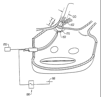
Figures 3-4 further show a circumferential ablation device assembly (100)
according to the
present invention during use in performing positioning step (3) and ablation
step (4) just described
with reference to Figure 3. Included in the circumferential ablation device
assembly (100) are
guiding catheter (101), guidewire (102), and circumferential ablation catheter
(103).
More specifically, Figure 4 shows guiding catheter (101) subsequent to
performing a
transeptal access method according to Figure 3, and also shows guidewire (102)
subsequent to
advancement and positioning within a pulmonary vein, also according to step
(3) of Figure 3. Figure
4 shows circumferential ablation catheter (103) as it tracks coaxially over
guidewire (102) with a
distal guidewire tracking member, which is specifically shown only in part at
first and second distal
guidewire ports (142,144) located on the distal end portion (132) of an
elongate catheter body (130).
A guidewire lumen (not shown) extends between the first and second distal
guidewire ports
(142,144) and is adapted to slideably receive and track over the guidewire. In
the particular variation
of Figure 4, the second distal guidewire port (142) is located on a distal end
portion (132) of the
elongate catheter body (130), although proximally of first distal guidewire
port (142).
-26-
CA 02294927 2007-09-28
As would be apparent to one of ordinary skill, the distal guidewire tracking
member shown
in Figure 4 and just described may be slideably coupled to the guidewire
externally of the body in
a "backloading" technique after the guidewire is first positioned in the
pulmonary vein. Furthermore,
there is no need in this guidewire tracking variation for a guidewire lumen in
the proximal portions
of the elongate catheter body (130), which allows for a reduction in the outer
diameter of the catheter
shaft in that region. Nevertheless, it is further contemplated that a design
which places the second
distal guidewire port on the proximal end portion of the elongate catheter
body would also be
acceptable, as is described below, for example, with reference to the
perfusion embodiment of
Figures 6A-B.
In addition, the inclusion of a guidewire lumen extending within the elongate
body between
first and second ports, as provided in Figure 4, should not limit the scope of
acceptable guidewire
tracking members according to the present invention. Other guidewire tracking
members which form
a bore adapted to slideably receive and track over a guidewire are also
considered acceptable, such
as, for example, the structure adapted to engage a guidewire as described in
U.S. Patent No.
5,505,702 to Arney.
While the assemblies and methods shown variously throughout the Figures
include a
guidewire coupled to a guidewire tracking member on the circumferential
ablation catheter, other
detailed variations may also be suitable for positioning the circumferential
ablation element at the
ablation region in order to form a circumferential conduction block there. For
example, an alternative
circumferential ablation catheter not shown may include a"fixed-wire"-type of
design wherein a
guidewire is integrated into the ablation catheter as one unit. In another
alternative assembly, the
same type of sub-selective sheaths described above with reference to U.S.
Patent No. 5,575,766 to
Swartz for advancing a guidewire into a pulmonary vein may also be used for
advancing a
circumferential ablation catheter device across the atrium and into a
pulmonary vein.
Figure 4 also shows circumferential ablation catheter (103) with a
circumferential ablation
element (160) formed on an expandable member (170). The expandable member
(170) is shown in
Figure 4 in a radially collapsed position adapted for percutaneous
translumenal delivery into the
pulmonary vein according to positioning step (3) of Figure 3. However,
expandable member (170)
is also adjustable to a radially expanded position
-27-
CA 02294927 1999-12-29
WO 99/02096 PCT/US98/14220
when actuated by an expansion actuator (175), as shown in Figure 5. Expansion
actuator
(175) may include, but is not limited to, a pressurizeable fluid source.
According to the
expanded state shown in Figure 5, expandable member (170) includes a working
length L
relative to the longitudinal axis of the elongate catheter body which has a
larger expanded
outer diameter OD than when in the radially collapsed position. Furthermore,
the
expanded outer diameter OD is sufficient to circumferentially engage the
ablation region of
the pulmonary vein. Therefore, the terms "working length" are herein intended
to mean
the length of an expandable member which, when in a radially expanded
position, has an
expanded outer diameter that is: (a) greater than the outer diameter of the
expandable
member when in a radially collapsed position; and (b) sufficient to engage a
body space
wall or adjacent ablation region surrounding the expandable member, at least
on two
opposing internal sides of the body space wall or adjacent ablation region,
with sufficient
surface area to anchor the expandable member.
Circumferential ablation element (160) also includes a circumferential band
(152)
on the outer surface of working length L which is coupled to an ablation
actuator (190) at a
proximal end portion of the elongate catheter body (shown schematically).
After
expandable member (170) is adjusted to the radially expanded position and at
least a
portion of working length L circumferentially engages the pulmonary vein wall
in the
ablation region, the circumferential band (152) of the circumferential
ablation element
(160) is actuated by ablation actuator (190) to ablate the surrounding
circumferential path
of tissue in the pulmonary vein wall, thereby forming a circumferential lesion
that
circumscribes the pulmonary vein lumen and transects the electrical
conductivity of the
pulmonary vein to block conduction in a direction along its longitudinal axis.
Figure 6A shows another circumferential ablation catheter (203) during use
also
according to the method of Figure 3, wherein a perfusion lumen (260) (shown in
phantom
in Figure 6B) is formed within the distal end portion (232) of elongate
catheter body (230).
The perfusion lumen (260) in this example is formed between a distal perfusion
port,
which in this example is the first distal guidewire port (242), and proximal
perfusion port
(244). Proximal perfusion port (244) is formed through the wall of the
elongate catheter
body (230) and communicates with the guidewire lumen (not shown) which also
forms the
perfusion lumen between the distal and proximal perfusion ports. In the
particular design
shown, after the guidewire has provided for the placement of the ablation
element into the
28
SUBSTITUTE SHEET (RULE 26)
CA 02294927 1999-12-29
WO 99/02096 PCTIUS98/14220
pulmonary vein, the guidewire is withdrawn proximally of the proximal
perfusion port
(244) (shown schematically in shadow) so that the lumen between the ports is
clear for
antegrade blood flow into the distal perfusion port (242), proximally along
the perfusion
lumen, out the proximal perfusion port (244) and into the atrium (perfusion
flow shown
schematically with arrows).
Further to the perfusion design shown in Figures 6A-B, guidewire (102) is
positioned in a guidewire lumen which extends the entire length of the
elongate catheter
body (230) in an "over-the-wire"-type of design, which facilitates the
proximal withdrawal
of the guidewire to allow for perfusion while maintaining the ability to
subsequently
t o readvance the guidewire distally through the first distal guidewire port
(242) for catheter
repositioning. In one alternative variation not shown, the guidewire is simply
withdrawn
and disengaged from the second distal guidewire port (244), in which case the
circumferential ablation catheter must generally be withdrawn from the body in
order to
recouple the distal guidewire tracking member with the guidewire.
In another alternative perfusion variation not shown which is a modification
of the
embodiment of Figure 6A, a proximal perfusion port is provided as a separate
and distinct
port positioned between the second distal guidewire port (244) and the
expandable member
(270), which allows for proximal withdrawal of the guidewire to clear the
guidewire lumen
and thereby form a perfusion lumen between the first distal guidewire port and
the
proximal perfusion port. The guidewire of this alternative variation, however,
remains
engaged within the guidewire lumen between the second distal guidewire port
and the
proximal perfusion port.
Passive perfusion during expansion of the expandable member is believed to
minimize stasis and allow the target pulmonary vein to continue in its atrial
filling function
during the atrial arrhythmia treatment procedure. Without this perfusion
feature, the
expandable member when in the radially expanded position during ablation
blocks the
flow from the vein into the atrium, which flow stasis may result in
undesirable
thrombogenesis in the pulmonary vein distally to the expandable member. In
addition, in
cases where the ablation element is adapted to ablate tissue with heat
conduction at the
3o ablation region, as described by reference to more detailed embodiments
below, the
perfusion feature according to the variation of Figures 6A-B may also provide
a cooling
29
SUBSTITUTE SHEET (RULE 26)
CA 02294927 1999-12-29
WO 99/02096 PCT/US98/14220
function in the surrounding region, including in the blood adjacent to the
expandable
member.
Moreover, in addition to the specific perfusion structure shown and described
by
reference to Figures 6A-B, it is to be further understood that other
structural variants which
allow for perfusion flow during expansion of the expandable element may
provide suitable
substitutes according to one of ordinary skill without departing from the
scope of the
present invention.
Figure 7 shows pulmonary vein (52) after removing the circumferential ablation
device assembly subsequent to forming a circumferential lesion (70) around the
ablation
region of the pulmonary vein wall (53) according to the use of the
circumferential ablation
device assembly shown in stepwise fashion in Figures 3-6. Circumferential
lesion (70) is
shown located along the pulmonary vein adjacent to the pulmonary vein ostium
(54), and
is shown to also be "transmural," which is herein intended to mean extending
completely
through the wall, from one side to the other. Also, the circumferential lesion
(70) is shown
in Figure 7 to form a "continuous" circumferential band, which is herein
intended to mean
without gaps around the pulmonary vein wall circumference, thereby
circumscribing the
pulmonary vein lumen.
It is believed, however, that circumferential catheter ablation with a
circumferential
ablation element according to the present invention may leave some tissue,
either
transmurally or along the circumference of the lesion, which is not actually
ablated, but
which is not substantial enough to allow for the passage of conductive
signals. Therefore,
the terms "transmural" and "continuous" as just defined are intended to have
functional
limitations, wherein some tissue in the ablation region may be unablated but
there are no
functional gaps which allow for symptomatically arrhythmogenic signals to
conduct
through the conduction block and into the atrium from the pulmonary vein.
Moreover, it is believed that the functionally transmural and continuous
lesion
qualities just described are characteristic of a completed circumferential
conduction block
in the pulmonary vein. Such a circumferential conduction block thereby
transects the vein,
isolating conduction between the portion of the vein on one longitudinal side
of the lesion
and the portion on the other side. Therefore, any foci of originating
arrhythmogenic
conduction which is opposite the conduction block from the atrium is prevented
by the
SUBSTITUTE SHEET (RULE 26)
CA 02294927 1999-12-29
WO 99/02096 PCT/US98/14220
conduction block from conducting down into the atrium and atrial arrhythmic
affects are
therefore nullified.
Figures 8A-B show a further variation of the present invention, wherein a
circumferential ablation member (350) includes a radially compliant expandable
member
(370) which is adapted to conform to a pulmonary vein ostium (54) at least in
part by
adjusting it to a radially expanded position while in the left atrium and then
advancing it
into the ostium. Figure 8A shows expandable member (370) after being adjusted
to a
radially expanded position while located in the left atrium (50). Figure 8B
further shows
expandable member (370) after being advanced into the pulmonary vein (52)
until at least
io a portion of the expanded working length L of circumferential ablation
member (350),
which includes a circumferential band (352), engages the pulmonary vein ostium
(54).
Figure 8C shows a portion of a circumferential lesion (72) which forms a
circumferential
conduction block in the region of the pulmonary vein ostium (54) subsequent to
actuating
the circumferential ablation element to form the circumferential lesion.
In addition to conforming to the pulmonary vein ostium, expandable member
(370)
is also shown in Figure 8B to engage a circumferential path of tissue along
the left
posterior atrial wall which surrounds ostium (54). Moreover, circumferential
bank (352) of
the circumferential ablation member is also thereby adapted to engage that
atrial wall
tissue. Therefore, the circumferential conduction block formed according to
the method
shown and just described in sequential steps by reference to Figures 8A-B, as
shown in-
part in Figure 8C, includes ablating the circumferential path of atrial wall
tissue which
surrounds ostium (54). Accordingly, the entire pulmonary vein, including the
ostium, is
thereby electrically isolated from at least a substantial portion of the left
atrial wall which
includes the other of the pulmonary vein ostia, as would be apparent to one of
ordinary
skill according to the sequential method steps shown in Figures 8A-B and by
further
reference to the resulting circumferential lesion (72) shown in Figure 8C.
Figures 8D-E show another highly beneficial circumferential ablation device
embodiment and use thereof for electrically isolating pulmonary vein and
ostium from a
substantial portion of the left posterior atrial wall. However, unlike the
embodiment
previously shown and described by reference to Figures 8A-C, the Figure 8D-E
embodiment isolates the pulmonary vein without also ablating tissue along the
lumen or
31
SUBSTITUTE SHEET (RULE 26)
CA 02294927 2007-09-28
lining of the pulmonary vein or ostium, as is apparent by reference to the
resulting
circumferential conduction block shown in Figure 8f.
In more detail, Figure 8D shows a similar device assembly as that shown in
Figures 8A-
B, except that circumferential band (352') has a geometry (primarily width)
and position along
expandable member (370') (having a proximal end (372') and a distal end
(374')) such that it is
adapted to engage only a circumferential path of tissue along the left
posterior atrial wall which
surrounds the pulmonary vein ostium. In one aspect of this embodiment, the
compliant nature of
the expandable member may be self-conforming to the region of the ostium such
that the
circumferential band is placed against this atrial wall tissue merely by way
of conformability.
In another variation, a"pear"-shaped expandable member or balloon that
includes a
contoured taper may be suitable for use according to the Figure 8D embodiment,
as is shown by
way of example in Figure 8E. Such a pear shape may be preformed into the
expandable member
or balloon, or the member may be adapted to form this shape by way of
controlled compliance as
it expands, such as for example by the use of composite structures within the
balloon
construction. In any case, according to the "pear"-shaped variation, the
circumferential band
(352') of the ablation member is preferably placed along the surface of the
contoured taper which
is adapted to face the left posterior atrial wall during use according to the
method illustrated by
Figure 8D. It is further contemplated that the ablation element may be further
extended or
alternatively positioned along other portions of the taper, such as is shown
by example in shadow
at extended band (352") in Figure 8E. Accordingly, the variation shown in
Figure 8E to include
extended band (352") may also adapt this particular device embodiment for use
in forming
circumferential conduction blocks also along tissue within the pulmonary vein
and ostium, such
as according to the previously described method shown in Figures 8A-C.
The method of forming a circumferential conduction block along a
circumferential path
of tissue along a left posterior atrial wall and which surrounds a pulmonary
vein ostium without
ablating the tissue of the vein or ostium should not be limited to the
particular device
embodiments just illustrated by reference to Figures 8D-F. Other device
variations may be
acceptable substitutes for use according to this method. In one particular
example which is
believed to be suitable, a "looped" ablation member such as the embodiment
illustrated below by
reference to Figure 15 may be adapted to form a "looped"
-32-
CA 02294927 2007-09-28
ablation element within the left atrium and then be advanced against the left
posterior atrial wall such
that the loop engages the circumferential path of tissue along the atrial wall
and which surrounds a
vein ostium. Thereafter, the looped ablation element may be actuated to ablate
the engaged tissue,
such as for further illustration like a branding iron forming the
predetermined pattern around the
pulmonary veinos (i.e., ostium). In addition, other device or method
variations may also be suitable
substitutes according to one of ordinary skill.
Figures 9A-D collectively show a circumferential ablation device assembly
according to the
present invention as it is used to form a circumferential conduction block
adjunctively to the
formation of long linear lesions in a less-invasive "maze"-type procedure, as
introduced above for
the treatment of multiwavelet reentrant type fibrillation along the left
atrial wall.
More specifically, Figure 9A diagrammatically shows a summary of steps for
performing a
"maze"-type procedure by forming circumferential conduction blocks that
intersect with long linear
conduction blocks formed between the pulmonary veins. A box-like conduction
block surrounding
an arrhythmogenic atrial wall region bounded by the pulmonary veins may be
created by forming
long linear lesions between anchors in all pairs of adjacent pulmonary vein
ostia, such as is shown
in part in steps (5) and (6) of Figure 9A. However, it is further believed
that, in some particular
applications, such linear lesions may be made sufficiently narrow with respect
to the surface area of
the pulmonary vein ostia that they may not intersect, thereby leaving gaps
between them which may
present proarrhythmic pathways for abnormal conduction into and from the box,
such as is shown
between linear lesions (57, 58, 59) in Figure 9B. Therefore, by forming the
circumferential
conduction block according to step (7) of Figure 9A, and as shown by use of
circumferential ablation
member (450) in Figure 9C, the linear lesions are thereby bridged and the gaps
are closed.
5 In a further variation to the specific embodiments shown in Figures 9B-C,
Figure 9D shows
another circumferential ablation device assembly which includes both
circumferential and linear
ablation elements (452,461), respectively. Circumferential ablation member
(450) is shown to
include an expandable member (470) which is adjusted to a radially expanded
position that is
asymmetric to the underlying catheter shaft. Linear ablation member (460)
extends along the
10 elongate body proximally from the circumferential ablation member (450).
When expanded
sufficiently to engage the pulmonary vein wall, expandable member (470)
provides at least a portion
of an anchor for a first end (462) of linear ablation member (460).
-33-
CA 02294927 2007-09-28
A shaped stylet (466) is shown in shadow in Figure 9D within the elongate
catheter body in
the region of the second end (464) of the linear ablation member (460). Shaped
stylet (466) is
adapted to push the second end (464) into an adjacent pulmonary vein ostium
such that the linear
ablation member (460) is adapted to substantially contact the left atrial wall
between the adjacent
vein ostia to form the linear ablation according to the method of Figure 9A.
In addition to the use
of shaped stylet (466), it is further contemplated that a second anchor may be
used adjacent to second
end (464), such as for example an intermediate guidewire tracking member
adapted to track over a
guidewire engaged to the pulmonary vein, as shown in Figure 9E at intermediate
guidewire tracking
member (466') which is engaged over guidewire (467).
In a yet a further variation to the specific embodiment shown in Figure 9D,
Figure 9E shows
a circumferential ablation device assembly which includes both circumferential
and linear ablation
elements (452,460), respectively. Circumferential ablation member (450) is
shown to include an
expandable member (470) which is adjusted to a radially expanded position that
is asymmetric to
the underlying catheter shaft. Linear ablation member (460) extends along the
elongate body
proximally from the circumferential ablation member (450). When expanded
sufficiently to engage
the pulmonary vein wall, expandable member (470) provides at least a portion
of an anchor for a first
end (462) of linear ablation member (460).
Moreover, the method shown schematically in Figure 9A and also in various
detail by
reference to Figures 9B-C provides a specific sequence of steps for the
purpose of illustration.
According to this illustrative sequence, the linear lesions are formed first
and then are connected
thereafter with the circumferential conduction block. However, a
circumferential conduction block
may be formed prior to the formation of the linear lesions or conduction
blocks, or in any other
combination or sub-combination of sequential steps, so long as the resulting
combination of lesions
allows for the circumferential block to intersect with and connect with the
linear lesions. In addition,
the circumferential
-34-
CA 02294927 1999-12-29
WO 99/02096 PCTIUS98/14220
conduction block which connects the linear lesions may also include a
circumferential path
of tissue which surrounds and electrically isolates the pulmonary vein ostium
from the rest
of the left posterior atrial wall, such as for example by considering the
embodiments just
shown and described by reference to Figures 9A-E in view of the embodiment
previously
shown and described in relation to Figure 8C above.
In addition to the particular embodiments just shown and described by
reference to
Figures 9A-E, other methods are also contemplated for combining
circumferential and
linear conduction blocks device assemblies and uses in order to perform a less-
invasive
"maze"-type procedure. For example, Figure 9F shows one particular lesion
pattern which
results by combining a circumferential conduction block, formed according to
the previous
embodiments of Figures 8A-C, with a pair of linear lesions which are formed
according to
the method illustrated by Figure 9B. In a further example shown in Figure 9G,
another
lesion pattern is formed by combining the pair of linear lesions of Figure 9B
with a
circumferential conduction block formed according to the embodiments which are
previously illustrated above by reference to Figures 9D-F. While the resulting
lesion
patterns of Figures 9F and 9G differ slightly as regards the particular
geometry and
position of the circumferential conduction block formed, the two variations
are also similar
in that the circumferential conduction block includes a circumferential path
of atrial wall
tissue. When such circumferential conduction blocks are formed between
adjacent
pulmonary vein ostia, shorter linear lesions are therefore sufficient to
bridge the
circumferential lesions during the overall "maze"-type procedure.
To this end, the invention further contemplates one further variation for a
less-
invasive "maze"-type procedure (not shown) wherein multiple circumferential
conduction
blocks are formed in atrial wall tissue such that each pulmonary vein ostium
is surrounded
by and is electrically isolated with one circumferential conduction block. A
series of four
linear lesions may be formed between the various pairs of adjacent ostia and
with just
sufficient length to intersect with and bridge the corresponding adjacent
circumferential
blocks. A box-like conduction block is thereby formed by the four
circumferential
conduction blocks and the four bridging linear lesions. A fifth linear lesion
may be also
formed between at least a portion of the box-like conduction block and another
predetermined location, such as for example the mitral value annulus.
SUBSTITUTE SHEET (RULE 26)
CA 02294927 1999-12-29
WO 99/02096 PCT/US98/14220
Figure 9H shows yet a further variation for forming circumferential conduction
blocks along atrial wall tissue around the pulmonary vein ostia during a less
invasive
"maze"-type procedure. According to this further variation, the
circumferential conduction
block patterns formed around each of two adjacent superior and inferior
pulmonary vein
ostia are shown in Figure 9H to intersect, thereby alleviating the need for a
linear lesion in
order to form a conduction block between the ostia. Furthermore, the distances
between
the inferior and superior ostia, both on the right and left side of the
posterior atrial wall, are
believed to be significantly shorter than the distances between the two
adjacent superior or
inferior ostia. Therefore, Figure 9H only shows the overlapping
circumferential
conduction blocks as just described to be positioned vertically between the
inferior-
superior pairs of adjacent ostia, and further shows linear lesions which are
used to connect
the right and left sided ostia of the superior and inferior pairs. In some
instances these
linear lesions will not be required to cure, treat or prevent a particular
atrial arrhythmia
condition. However, other combinations of these patterns are further
contemplated, such
as for example using only overlapping circumferential conduction blocks
between all
adjacent pairs of ostia in order to form the entire "maze"-type left atrial
pattern.
Figure 10 diagrammatically shows a further method for using the
circumferential
ablation device assembly of the present invention wherein electrical signals
along the
pulmonary vein are monitored with a sensing element before and after ablation
according
to steps (8) and (9), respectively. Signals within the pulmonary vein are
monitored prior to
forming a conduction block, as indicated in step (8) in Figure 10, in order to
confirm that
the pulmonary vein chosen contains an arrhythmogenic origin for atrial
arrhythmia.
Failure to confirm an arrhythmogenic origin in the pulmonary vein,
particularly in the case
of a patient diagnosed with focal arrhythmia, may dictate the need to monitor
signals in
another pulmonary vein in order to direct treatment to the proper location in
the heart. In
addition, monitoring the pre-ablation signals may be used to indicate the
location of the
arrhythmogenic origin of the atrial arrhythmia, which information helps
determine the best
location to form the conduction block. As such, the conduction block may be
positioned to
include and therefore ablate the actual focal origin of the arrhythmia, or may
be positioned
between the focus and the atrium in order to block aberrant conduction from
the focal
origin and into the atrial wall.
36
SUBSTITUTE SHEET (RULE 26)
CA 02294927 1999-12-29
WO 99/02096 PCT/US98/14220
In addition or in the alternative to monitoring electrical conduction signals
in the
pulmonary vein prior to ablation, electrical signals along the pulmonary vein
wall may also
be monitored by the sensing element subsequent to circumferential ablation,
according to
step (9) of the method of Figure 10. This monitoring method aids in testing
the efficacy of
the ablation in forming a complete conduction block against arrhythmogenic
conduction.
Arrhythmogenic firing from the identified focus will not be observed during
signal
monitoring along the pulmonary vein wall when taken below a continuous
circumferential
and transmural lesion formation, and thus would characterize a successful
circumferential
conduction block. In contrast, observation of such arrhythmogenic signals
between the
io lesion and the atrial wall characterizes a functionally incomplete or
discontinuous
circumference (gaps) or depth (transmurality) which would potentially identify
the need
for a subsequent follow-up procedure, such as a second circumferential
lesioning
procedure in the ablation region.
A test electrode may also be used in a "post ablation" signal monitoring
method
according to step (10) of Figure 10. In one particular embodiment not shown,
the test
electrode is positioned on the distal end portion of an elongate catheter body
and is
electrically coupled to a current source for firing a test signal into the
tissue surrounding
the test electrode when it is placed distally or "upstream" of the
circumferential lesion in
an attempt to simulate a focal arrhythmia. This test signal generally
challenges the
robustness of the circumferential lesion in preventing atrial arrhythmia from
any such
future physiologically generated aberrant activity along the suspect vein.
Further to the signal monitoring and test stimulus methods just described,
such
methods may be performed with a separate electrode or electrode pair located
on the
catheter distal end portion adjacent to the region of the circumferential
ablation element, or
may be performed using one or more electrodes which form the circumferential
ablation
element itself, as will be further developed below.
Circumferential Ablation Member
The designs for the expandable member and circumferential ablation element for
use in the circumferential ablation device assembly of the present invention
have been
described generically with reference to the embodiments shown in the previous
Figures.
37
SUBSTITUTE SHEET (RULE 26)
CA 02294927 1999-12-29
WO 99/02096 PCTIUS98/14220
Examples of more specific expandable member and ablation element embodiments
which
are adapted for use in the assembly of the present invention are further
provided as follows.
Notwithstanding their somewhat schematic detail, the circumferential ablation
members shown in the previous figures do illustrate one particular embodiment
wherein a
circumferential electrode element circumscribes an outer surface of an
expandable
member. The expandable member of the embodiments shown may take one of several
different forms, although the expandable member is generally herein shown as
an
inflatable balloon that is coupled to an expansion actuator (175) which is a
pressurizeable
fluid source. The balloon is preferably made of a polymeric material and forms
a fluid
chamber which communicates with a fluid passageway (not shown in the figures)
that
extends proximally along the elongate catheter body and terminates proximally
in a
proximal fluid port that is adapted to couple to the pressurizeable fluid
source.
In one expandable balloon variation, the balloon is constructed of a
relatively
inelastic polymer such as a polyethylene ("PE"; preferably linear low density
or high
density or blends thereof), polyolefin copolymer ("POC"), polyethylene
terepthalate
("PET"), polyimide, or a nylon material. In this construction, the balloon has
a low radial
yield or compliance over a working range of pressures and may be folded into a
predetermined configuration when deflated in order to facilitate introduction
of the balloon
into the desired ablation location via known percutaneous catheterization
techniques. In
this variation, one balloon size may not suitably engage all pulmonary vein
walls for
performing the circumferential ablation methods of the present invention on
all needy
patients. Therefore, it is further contemplated that a kit of multiple
ablation catheters, with
each balloon working length having a unique predetermined expanded diameter,
may be
provided from which a treating physician may chose a particular device to meet
a
particular patient's pulmonary vein anatomy.
In an alternative expandable balloon variation, the balloon is constructed of
a
relatively compliant, elastomeric material, such as, for example (but not
limited to), a
silicone, latex, polyurethane, or mylar elastomer. In this construction, the
balloon takes the
form of a tubular member in the deflated, non-expanded state. When the elastic
tubular
balloon is pressurized with fluid such as in the previous, relatively non-
compliant example,
the material forming the wall of the tubular member elastically deforms and
stretches
radially to a predetermined diameter for a given inflation pressure. It is
further
38
SUBSTITUTE SHEET (RULE 26)
CA 02294927 1999-12-29
WO 99/02096 PCT/US98/14220
contemplated that the compliant balloon may be constructed as a composite,
such as, for
example, a latex or silicone balloon skin which includes fibers, such as
metal, Kevlar, or
nylon fibers, which are embedded into the skin. Such fibers, when provided in
a
predetermined pattern such as a mesh or braid, may provide a controlled
compliance along
a preferred axis, preferably limiting longitudinal compliance of the
expandable member
while allowing for radial compliance.
It is believed that, among other features, the relatively compliant variation
may
provide a wide range of working diameters, which may allow for a wide variety
of
patients, or of vessels within a single patient, to be treated with just one
or a few devices.
Furthermore, this range of diameters is achievable over a relatively low range
of pressures,
which is believed to diminish a potentially traumatic vessel response that may
otherwise be
presented concomitant with higher pressure inflations, particularly when the
inflated
balloon is oversized to the vessel. In addition, the low-pressure inflation
feature of this
variation is suitable for the present invention because the functional
requirement of the
expandable balloon is merely to engage the ablation element against a
circumferential path
along the inner lining of the pulmonary vein wall.
Moreover, a circumferential ablation member is adapted to conform to the
geometry of the pulmonary vein ostium, at least in part by providing
substantial
compliance to the expandable member, as was shown and described previously by
reference to Figures 8A-B. Further to this conformability to pulmonary vein
ostium as
provided in the specific design of Figures 8A-B, the working length L of
expandable
member (370) is also shown to include a taper which has a distally reducing
outer diameter
from a proximal end (372) to a distal end (374). In either a compliant or the
non-compliant
balloon, such a distally reducing tapered geometry adapts the circumferential
ablation
element to conform to the funneling geometry of the pulmonary veins in the
region of their
ostia in order to facilitate the formation of a circumferential conduction
block there.
Further to the circumferential electrode element embodiment as shown variously
throughout the previous illustrative Figures, the circumferential electrode
element is
coupled to an ablation actuator (190). Ablation actuator (190) generally
includes a radio-
frequency ("RF") current source (not shown) that is coupled to both the RF
electrode
element and also a ground patch (195) which is in skin contact with the
patient to complete
an RF circuit. In addition, ablation actuator (190) preferably includes a
monitoring circuit
39
SUBSTITUTE SHEET (RULE 26)
CA 02294927 1999-12-29
WO 99/02096 PCT/US98/14220
(not shown) and a control circuit (not shown) which together use either the
electrical
parameters of the RF circuit or tissue parameters such as temperature in a
feedback control
loop to drive current through the electrode element during ablation. Also,
where a
plurality of ablation elements or electrodes in one ablation element are used,
a switching
means may be used to multiplex the RF current source between the various
elements or
electrodes.
Figures 11A-D show various patterns of electrically conductive,
circumferential
electrode bands as electrode ablation elements, each circumscribing an outer
surface of the
working length of an expandable member. Figures 11A-B show circumferential
ablation
lo member (550) to include a continuous circumferential electrode band (552)
that
circumscribes an outer surface of an expandable member (570). Figure 11B more
specifically shows expandable member (570) as a balloon which is fluidly
coupled to a
pressurizeable fluid source (175), and further shows electrode band
(circumferential
ablation element) (552) electrically coupled via electrically conductive lead
(554) to
ablation actuator (190). In addition, a plurality of apertures (572) are shown
in the balloon
skin wall of expandable member (570) adjacent to electrode band (552). The
purpose of
these apertures (572) is to provide a positive flow of fluid such as saline or
ringers lactate
fluid into the tissue surrounding the electrode band (552). Such fluid flow is
believed to
reduce the temperature rise in the tissue surrounding the electrode element
during RF
ablation.
The shapes shown collectively in Figures 11A-D allow for a continuous
electrode
band to circumscribe an expandable member's working length over a range of
expanded
diameters, a feature which is believed to be particularly useful with a
relatively compliant
balloon as the expandable member. In the particular embodiments of Figures 11A-
D, this
feature is provided primarily by a secondary shape given to the electrode band
relative to
the longitudinal axis of the working length of the expandable member.
Electrode band
(552) is thus shown in Figures 11A-B to take the specific secondary shape of a
modified
step curve. Other shapes than a modified step curve are also suitable, such as
the
serpentine or sawtooth secondary shapes shown respectively in Figures 11 C-D.
Other
shapes in addition to those shown in Figures 11A-D and which meet the defined
functional
requirements are further contemplated within the scope of the present
invention.
SUBSTITUTE SHEET (RULE 26)
CA 02294927 1999-12-29
WO 99/02096 PCT/US98/14220
In addition, the electrode band provided by the circumferential ablation
elements
shown in Figures 11 C-D and also shown schematically in Figures 3-6B has a
functional
band width w relative to the longitudinal axis of the working length which is
only required
to be sufficiently wide to form a complete conduction block against conduction
along the
walls of the pulmonary vein in directions parallel to the longitudinal axis.
In contrast, the
working length L of the respective expandable element is adapted to securely
anchor the
distal end portion in place such that the ablation element is firmly
positioned at a selected
region of the pulmonary vein for ablation. Accordingly, the band width w is
relatively
narrow compared to the working length L of the expandable element, and the
electrode
t o band may thus form a relatively narrow equatorial band which has a band
width that is less
than two-thirds or even one-half of the working length of the expandable
element.
Additionally, it is to be noted here and elsewhere throughout the
specification, that a
narrow band may be placed at locations other than the equator of the
expandable element,
preferably as long as the band is bordered on both sides by a portion of the
working length
L.
In another aspect of the narrow equatorial band variation for the
circumferential
ablation element, the circumferential lesion formed may also be relatively
narrow when
compared to its own circumference, and may be less than two-thirds or even one-
half its
own circumference on the expandable element when expanded. In one arrangement
which
is believed to be suitable for ablating circumferential lesions in the
pulmonary veins as
conduction blocks, the band width w is less than 1 cm with a circumference on
the working
length when expanded that is greater than 1.5 cm.
Figures 12A-B show a further variation of a circumferential ablation element
which
is adapted to maintain a continuous circumferential lesion pattern over a
range of expanded
diameters and which includes electrode elements that form a relatively narrow
equatorial
band around the working length of an expandable balloon member. In this
variation, a
plurality of individual electrode/ablation elements (562) are included in the
circumferential
ablation element and are positioned in spaced arrangement along an equatorial
band which
circumscribes an outer surface of the expandable member's working length L.
The size and spacing between these individual electrode elements (562), when
the
balloon is expanded, is adapted to form a substantially continuous
circumferential lesion in
pulmonary vein wall tissue when in intimal contact adjacent thereto, and is
further adapted
41
SUBSTITUTE SHEET (RULE 26)
CA 02294927 2007-09-28
to form such a lesion over a range of band diameters as the working length is
adjusted between a variety
of radially expanded positions. Each individual electrode element (562) has
two opposite ends
(563,564), respectively, along a long axis LA and also has a short axis SA,
and is positioned such that
the long axis LA is at an acute angle relative to the longitudinal axis LA of
the elongate catheter body
and expandable member (560). At least one of the ends (563,564) along the long
axis LA overlaps with
an end of another adjacent individual electrode element, such that there is a
region of overlap along
their circumferential aspect, i.e., there is a region of overlap along the
circumferential coordinates. The
terms "region of overlap along their circumferential coordinate" are herein
intended to mean that the
two adjacent ends each are positioned along the working length with a
circumferential and also a
longitudinal coordinate, wherein they share a common circumferential
coordinate. In this arrangement,
the circumferential compliance along the working length which accompanies
radial expansion of the
expandable member also moves the individual electrode elements apart along the
circumferential axis.
However, the spaced, overlapping arrangement described allows the individual
ablation elements to
maintain a certain degree of their circumferential overlap, or at least remain
close enough together, such
that a continuous lesion may be formed without gaps between the elements.
The construction for suitable circumferential electrode elements in the RF
variation of the
present invention, such as the various electrode embodiments described with
reference to Figures 11A-
12B, may comprise a metallic material deposited on the outer surface of the
working length using
conventional techniques, such as by plasma depositing, sputter coating,
chemical vapor deposition,
other known techniques which are equivalent for this purpose, or otherwise
affixing a metallic shaped
member onto the outer surface of the expandable member such as through known
adhesive bonding
techniques. Other RF electrode arrangements are also considered within the
scope of the present
invention, so long as they form a circumferential conduction block as
previously described. For
example, a balloon skin may itself be metallized, such as by mixing conductive
metal, including but
not limited to gold, platinum, or silver, with a polymer to form a compounded,
conductive matrix as
the balloon skin. Further to the circumferential electrode element embodiment
as shown variously
throughout the previous illustrative Figures, the circumferential electrode
element is coupled to an
ablation actuator (190) through electrically conductive leads (568).
Still further to the RF electrode embodiments, another circumferential
ablation member
variation (not shown) may also include an expandable member, such as an
-42-
CA 02294927 1999-12-29
WO 99/02096 PCT/US98/14220
inflatable balloon, that includes a porous skin that is adapted to allow
fluid, such as
hypertonic saline solution, to pass from an internal chamber defined by the
skin and
outwardly into surrounding tissues. Such a porous skin may be constructed
according to
several different methods, such as by forming holes in an otherwise contiguous
polymeric
material, including mechanically drilling or using laser energy, or the porous
skin may
simply be an inherently porous membrane. In any case, by electrically coupling
the fluid
within the porous balloon skin to an RF current source (preferably monopolar),
the porous
region of the expandable member serves as an RF electrode wherein RF current
flows
outwardly through the pores via the conductive fluid. In addition, it is
further
io contemplated that a porous outer skin may be provided externally of
another, separate
expandable member, such as a separate expandable balloon, wherein the
conductive fluid
is contained in a region between the porous outer skin and the expandable
member
contained therein. Various other "fluid electrode" designs than those
specifically herein
described may also be suitable according to one of ordinary skill upon review
of this
disclosure.
In the alternative, or in addition to the RF electrode variations just
described, the
circumferential ablation element may also include other ablative energy
sources or sinks,
and particularly may include a thermal conductor that circumscribes the outer
circumference of the working length of an expandable member. Examples of
suitable
thermal conductor arrangements include a metallic element which may, for
example, be
constructed as previously described for the more detailed RF embodiments
above.
However, in the thermal conductor embodiment such a metallic element would be
generally either resistively heated in a closed loop circuit internal to the
catheter, or
conductively heated by a heat source coupled to the thermal conductor. In the
latter case
of conductive heating of the thermal conductor with a heat source, the
expandable member
may be, for example, a polymeric balloon skin which is inflated with a fluid
that is heated
either by a resistive coil or by bipolar RF current. In any case, it is
believed that a thermal
conductor on the outer surface of the expandable member is suitable when it is
adapted to
heat tissue adjacent thereto to a temperature between 40deg and 80deg Celsius.
Further to the thermal conduction variation for the circumferential ablation
element, the perfusion balloon embodiment as shown in Figures 6A-B may be
particularly
useful in such a design. It is believed that ablation through increased
temperatures, as
43
SUBSTITUTE SHEET (RULE 26)
CA 02294927 1999-12-29
WO 99/02096 PCT/US98/14220
provided by example above may also enhance coagulation of blood in the
pulmonary vein
adjacent to the expandable member, which blood would otherwise remain stagnant
without
such a perfusion feature.
One further circumferential ablation element design which is believed to be
highly
useful in performing the methods according to the present invention is shown
in Figure 13
to include a circumferential ablation member(600) with two insulators
(602,604) that
encapsulate the proximal and distal ends, respectively, of the working length
L of an
expandable member (610). In the particular embodiment shown, the insulators
(602,604)
are thermal insulators, such as a thermal insulator comprising a Teflon
material.
1o Expandable member (610) is an inflatable balloon which has a balloon skin
(612) that is
thermally conductive to surrounding tissue when inflated with a heated fluid
which may
contain a radiopaque agent, saline fluid, ringers lactate, combinations
thereof, other known
biocompatible fluids having acceptable heat transfer properties for these
purposes, further
to the thermal conductor embodiments previously described. By providing these
spaced
insulators, a circumferential ablation element is formed as an equatorial band
(603) of
uninsulated balloon skin is located between the opposite insulators. In this
configuration,
the circumferential ablation element is able to conduct heat externally of the
balloon skin
much more efficiently at the uninsulated equatorial band (603) than at the
insulated
portions, and thereby is adapted to ablate only a circumferential region of
tissue in a
pulmonary vein wall which is adjacent to the equatorial band. It is further
noted that this
embodiment is not limited to an "equatorial" placement of the ablation
element. Rather, a
circumferential band may be formed anywhere along the working length of the
expandable
member and circumscribing the longitudinal axis of the expandable member as
previously
described.
Figure 13 further shows use of a radiopaque marker (620) to identify the
location of
the equatorial band (603) in order to facilitate placement of that band at a
selected ablation
region of a pulmonary vein via X-ray visualization. Radiopaque marker (620) is
opaque
under X-ray, and may be constructed, for example, of a radiopaque metal such
as gold,
platinum, or tungsten, or may comprise a radiopaque polymer such as a metal
loaded
polymer. Figure 13 shows radiopaque marker (620) positioned coaxially over an
inner
tubular member (621) which is included in a coaxial catheter design as would
be apparent
to one of ordinary skill. The present invention contemplates the combination
of such a
44
SUBSTITUTE SHEET (RULE 26)
CA 02294927 1999-12-29
WO 99/02096 PCT/US98/14220
radiopaque marker additionally in the other embodiments herein shown and
described. To
note, when the circumferential ablation member which forms an equatorial band
includes a
metallic electrode element, such electrode may itself be radiopaque and may
not require
use of a separate marker as just described.
The thermal insulator embodiment just described by reference to Figure 13 is
illustrative of a broader embodiment, wherein a circumferential ablation
member has an
ablating surface along the entire working length of an expandable member, but
is shielded
from releasing ablative energy into surrounding tissues except for along an
unshielded or
uninsulated equatorial band. As such, the insulator embodiment contemplates
other
ablation elements, such as the RF embodiments previously described above,
which are
provided along the entire working length of an expandable member and which are
insulated at their ends to selectively ablate tissue only about an uninsulated
equatorial
band.
In a further example using the insulator embodiment in combination with a
circumferential RF electrode embodiment, a metallized balloon which includes a
conductive balloon skin may have an electrical insulator, such as a polymeric
coating, at
each end of the working length and thereby selectively ablate tissue with
electricity
flowing through the uninsulated equatorial band. In this and other insulator
embodiments,
it is further contemplated that the insulators described may be only partial
and still provide
the equatorial band result. For instance, in the conductive RF electrode
balloon case, a
partial electrical insulator will allow a substantial component of current to
flow through the
uninsulated portion due to a "shorting" response to the lower resistance in
that region.
In still a further example of an insulator combined with an RF ablation
electrode, a
porous membrane comprises the entire balloon skin of an expandable member. By
insulating the proximal and distal end portions of the working length of the
expandable
member, only the pores in the unexposed equatorial band region are allowed to
effuse the
electrolyte which carries an ablative RF current.
Further to the expandable member design for use in a circumferential ablation
element according to the present invention, other expandable members than a
balloon are
also considered suitable. For example, in one expandable cage embodiment shown
in
Figure 14, cage (650) comprises coordinating wires (651) and is expandable to
engage a
desired ablation region in a pulmonary vein.
SUBSTITUTE SHEET (RULE 26)
CA 02294927 1999-12-29
WO 99/02096 PCT/US98/14220
The radial expansion of cage (650) is accomplished as follows. Sheath (652) is
secured around the wires proximally of cage (650). However, core (653), which
may be a
metallic mandrel such as stainless steel, extends through sheath (652) and
distally within
cage (650) wherein it terminates in a distal tip (656) . Wires (651) are
secured to distal tip
(656), for example, by soldering, welding, adhesive bonding, heat shrinking a
polymeric
member over the wires, or any combination of these methods. Core (653) is
slideable
within sheath (652), and may, for example, be housed within a tubular lumen
(not shown)
within sheath (652), the wires being housed between a coaxial space between
the tubular
lumen and sheath (652). By moving the sheath (652) relative to core (653) and
distal tip
(656)(shown by arrows in Figure 14), the cage (650) is collapsible along its
longitudinal
axis in order to force an outward radial bias (also shown with arrows in
Figure 14) to wires
(651) in an organized fashion to formed a working length of cage (650) which
is expanded
(not shown).
Further to the particular expandable cage embodiment shown in Figure 14, a
plurality of ablation electrodes (655) is shown, each being positioned on one
of wires (651)
and being similarly located along the longitudinal axis of the cage (650). The
radial bias
given to wires (651) during expansion, together with the location of the
ablation electrodes
(655), serves to position the plurality of ablation electrodes/elements (655)
along a
circumferential, equatorial band along the expanded working length of cage
(650). The
wires forming a cage according to this embodiment may also have another
predetermined
shape when in the radially expanded position. For example, a taper similar to
that shown
for expandable member (370) in Figures 8A-B may be formed by expanding cage
(650),
wherein the ablation element formed by ablation electrodes (655) may be
positioned
between the proximal end and the distal end of the taper.
Further to the construction of the embodiment shown in Figure 14, wires (651)
are
preferably metal, and may comprise stainless steel or a superelastic metal
alloy, such as an
alloy of nickel and titanium, or a combination of both. Regarding the case of
nickel and
titanium construction for wires (655), a separate electrical conductor may be
required in
order to actuate ablation electrodes (655) to efficiently emit ablative
current into
surrounding tissues. In the case where wires (651) are constructed of
stainless steel, they
may also serve as electrical conductors for ablation electrodes (655). Further
to the
stainless steel design, the wires (651) may be coated with an electrical
insulator to isolate
46
SUBSTITUTE SHEET (RULE 26)
CA 02294927 1999-12-29
WO 99/02096 PCT/US98/14220
the electrical flow into surrounding tissues at the site of the ablation
electrodes (655).
Moreover, the ablation electrodes (655) in the stainless steel wire variation
may be formed
simply by removing electrical insulation in an isolated region to allow for
current to flow
into tissue only from that exposed region.
In a further cage embodiment (not shown) to that shown in Figure 14, a
circumferential strip of electrodes may also be secured to the cage (650) such
that the strip
circumscribes the cage at a predetermined location along the cage's
longitudinal axis. By
expanding cage (650) as previously described, the strip of electrodes are
adapted to take a
circumferential shape according to the shape of the expanded cage (650). Such
an
electrode strip is preferably flexible, such that it may be easily
reconfigured when the cage
is adjusted between the radially collapsed and expanded positions and such
that the strip
may be easily advanced and withdrawn with the cage within the delivery sheath.
Furthermore, the electrode strip may be a continuous circumferential electrode
such as a
conductive spring coil, or may be a flexible strip which includes several
separate electrodes
along its circumferential length. In the latter case, the flexible strip may
electrically couple
all of the electrodes to a conductive lead that interfaces with a drive
circuit, or each
electrode may be separately coupled to one or more such conductive leads.
Another circumferential ablation element adapted for use in the
circumferential
conduction block assembly according to the present invention is shown in
Figure 15,
wherein circumferential ablation member (700) includes a looped member (710)
attached,
preferably by heat shrinking, to a distal end of a pusher (730). Looped member
(710) and
pusher (730) are slideably engaged within delivery sheath (750) such that
looped member
(710) is in a first collapsed position when positioned and radially confined
within delivery
sheath (750), and expands to a second expanded position when advanced distally
from
delivery sheath (750).
Looped member (710) is shown in more detail in Figure 15 to include a core
(712)
which is constructed of a superelastic metal alloy such as a nickel-titanium
alloy and which
has a looped portion with shape memory in the looped configuration. This
looped
configuration is shown in Figure 15 to be in a plane which is off-axis,
preferably
perpendicular, to the longitudinal axis of the pusher (730). This off-axis
orientation of the
loop is adapted to engage a circumferential path of tissue along a pulmonary
vein wall
which circumscribes the pulmonary vein lumen when the looped member (710) is
47
SUBSTITUTE SHEET (RULE 26)
CA 02294927 1999-12-29
WO 99/02096 PCT/US98/14220
delivered from the delivery sheath (750) when the delivery sheath is
positioned within the
vein lumen parallel to its longitudinal axis. An ablation electrode (714) is
also shown in
Figure 15 as a metallic coil which is wrapped around core (712) in its looped
portion.
Pusher (730) is further shown in Figure 15 to include a tubular pusher member
(732) which is heat shrunk over two ends (712') of core (712) which extend
proximally of
looped member (710) through pusher (730) in the particular variation shown.
While in this
embodiment core (712) extends through the pusher in order to provide stiffness
to the
composite design for the pusher, it is further contemplated that the
superelastic metal of the
core may be replaced or augmented in the pusher region with another different
mandrel or
io pusher core (not shown), such as a stiffer stainless steel mandrel. Also
shown within
pusher (730) is an electrically conductive lead (735) which is coupled to the
ablation
electrode (714) and which is also adapted in a proximal region of the pusher
(not shown) to
couple to an ablation actuator (190) such as an RF current source (shown
schematically).
Ultrasound Circumferential Ablation Member
Figures 16A-19B show various specific embodiments of a broader circumferential
ablation device assembly which utilizes an ultrasonic energy source to ablate
tissue. The
present circumferential ablation device has particular utility in connection
with forming a
circumferential lesion within or about a pulmonary vein ostium or within the
vein itself in
order to form a circumferential conductive block. This application of the
present ablation
device, however, is merely exemplary, and it is understood that those skilled
in the art can
readily adapt the present ablation device for applications in other body
spaces.
As common to each of the following embodiments, a source of acoustic energy is
provided a delivery device that also includes an anchoring mechanism. In one
mode, the
anchoring device comprises an expandable member that also positions the
acoustic energy
source within the body; however, other anchoring and positioning devices may
also be
used, such as, for example, a basket mechanism. In a more specific form, the
acoustic
energy source is located within the expandable member and the expandable
member is
adapted to engage a circumferential path of tissue either about or along a
pulmonary vein
in the region of its ostium along a left atrial wall. The acoustic energy
source in turn is
acoustically coupled to the wall of the expandable member and thus to the
circumferential
48
SUBSTITUTE SHEET (RULE 26)
CA 02294927 1999-12-29
WO 99/02096 PCT/US98/14220
region of tissue engaged by the expandable member wall by emitting a
circumferential and
longitudinally collimated ultrasound signal when actuated by an acoustic
energy driver.
The use of acoustic energy, and particularly ultrasonic energy, offers the
advantage of
simultaneously applying a dose of energy sufficient to ablate a relatively
large surface area
within or near the heart to a desired heating depth without exposing the heart
to a large
amount of current. For example, a collimated ultrasonic transducer can form a
lesion,
which has about a 1.5 mm width, about a 2.5 mm diameter lumen, such as a
pulmonary
vein and of a sufficient depth to form an effective conductive block. It is
believed that an
effective conductive block can be formed by producing a lesion within the
tissue that is
t o transmural or substantially transmural. Depending upon the patient as well
as the location
within the pulmonary vein ostium, the lesion may have a depth of i millimeter
to 10
millimeters. It has been observed that the collimated ultrasonic transducer
can be powered to
provide a lesion having these parameters so as to form an effective conductive
block between
the pulmonary vein and the posterior wall of the left atrium.
With specific reference now to the embodiment illustrated in Figures 16A
through
16D, a circumferential ablation device assembly (800) includes an elongate
body (802)
with proximal and distal end portions (810,812), an expandable balloon (820)
located
along the distal end portion (812) of elongate body (802), and a
circumferential ultrasound
transducer (830) which forms a circumferential ablation member which is
acoustically
coupled to the expandable balloon (820). In more detail, Figures 16A-C
variously show
elongate body (802) to include guidewire lumen (804), inflation lumen (806),
and
electrical lead lumen (808). The ablation device, however, can be of a self
steering type
rather than an over-the-wire type device.
Each lumen extends between a proximal port (not shown) and a respective distal
port, which distal ports are shown as distal guidewire port (805) for
guidewire lumen
(804), distal inflation port (807) for inflation lumen (806), and distal lead
port (809) for
electrical lead lumen (808). Although the guidewire, inflation and electrical
lead lumens
are generally arranged in a side-by-side relationship, the elongate body (802)
can be
constructed with one or more of these lumens arranged in a coaxial
relationship, or in any
of a wide variety of configurations that will be readily apparent to one of
ordinary skill in
the art.
49
SUBSTITUTE SHEET (RULE 26)
CA 02294927 2007-09-28
In addition, the elongate body (802) is also shown in Figuresl 6A andl 6C to
include an inner
member (803) which extends distally beyond distal inflation and lead ports
(807,809), through an
interior chamber formed by the expandable balloon (820), and distally beyond
expandable balloon (820)
where the elongate body terminates in a distal tip. The inner member (803)
forms the distal region for
the guidewire lumen (804) beyond the inflation and lead ports, and also
provides a support member for
the cylindrical ultrasound transducer (830) and for the distal neck ofthe
expansion balloon, as described
in more detail below.
One more detailed construction for the components of the elongate body (802)
which is believed
to be suitable for use in transeptal left atrial ablation procedures is as
follows. The elongate body (802)
itself may have an outer diameter provided within the range of from about 5
French (1.65 mm) to about
10 French (3.3 mm), and more preferable from about 7 French (2.31 mm) to about
9 French (2.97 mm).
The guidewire lumen preferably is adapted to slideably receive guidewires
ranging from about 0.0 10
inch (0.254 mm) to about 0.038 inch (0.965 mm) in diameter, and preferably is
adapted for use with
guidewires ranging from about 0.018 inch (0.457 mm) to about 0.035 inch (0.889
mm) in diameter.
Where a 0.035 inch (0.889 mm) guidewire is to be used, the guidewire lumen
preferably has an inner
diameter of 0.040 inch (1.02 mm) to about 0.042 inch (1.07 mm). In addition,
the inflation lumen
preferably has an inner diameter of about 0.020 inch (0.508 mm) in order to
allow for rapid deflation
times, although may vary based upon the viscosity of inflation medium used,
length of the lumen, and
other dynamic factors relating to fluid flow and pressure.
In addition to providing the requisite lumens and support members for the
ultrasound transducer
assembly, the elongate body (802) of the present embodiment must also be
adapted to be introduced
into the left atrium such that the distal end portion with balloon and
transducer may be placed within
the pulmonary vein ostium in a percutaneous translumenal procedure, and even
more preferably in a
transeptal procedure as otherwise herein provided. Therefore, the distal end
portion (812) is preferably
flexible and adapted to track over and along a guidewire seated within the
targeted pulmonary vein. In
one further more detailed construction which is believed to be suitable, the
proximal end portion is
adapted to be at least 30% more stiff than the distal end portion. According
to this relationship, the
proximal end portion may be suitably adapted to provide push transmission to
the distal end portion
while the distal end portion is suitably adapted to track through bending
anatomy during in vivo
delivery of the distal end portion of the device into the desired ablation
region.
Notwithstanding the specific device constructions just described, other
delivery mechanisms
-50-
CA 02294927 2007-09-28
for delivering the ultrasound ablation member to the desired ablation region
are also contemplated. For
example, while the Figure 1 6A variation is shown as an "overthe-wire"
catheter construction, other
guidewire tracking designs may be suitable substitutes, such as, for example,
catheter devices which
are known as "rapid exchange" or "monorail" variations wherein the guidewire
is only housed coaxially
within a lumen of the catheter in the distal regions of the catheter. In
another example, a deflectable tip
design may also be a suitable substitute and which is adapted to independently
select a desired
pulmonary vein and direct the transducer assembly into the desired location
for ablation. Further to this
latter variation, the guidewire lumen and guidewire of the Figurel 6A
variation may be replaced with
a "pullwire" lumen and associated fixed pullwire which is adapted to deflect
the catheter tip by applying
tension along varied stiffness transitions along the catheter's length. Still
further to this pullwire
variation, acceptable pullwires may have a diameter within the range from
about 0.008 inch (0.203 mm)
to about 0.020 inch (0.508 mm), and may further include a taper, such as, for
example, a tapered outer
diameter from about 0.020 inch (0.508 mm) to about 0.008 inch (0.203 mm).
More specifically regarding expandable balloon (820) as shown in varied detail
between
Figuresl 6A and 16C, a central region (822) is generally coaxially disposed
over the inner member
(803) and is bordered at its end neck regions by proximal and distal adaptions
(824,826). The proximal
adaption (824) is sealed over elongate body (802) proximally of the distal
inflation and the electrical
lead ports (807,809), and the distal adaption (826) is sealed over inner
member (803). According to this
arrangement, a fluid tight interior chamber is formed within expandable
balloon (820). This interior
chamber is fluidly coupled to a pressurizeable fluid source (not shown) via
inflation lumen (806). In
addition to the inflation lumen (806), electrical lead lumen (808) also
communicates with the interior
chamber of expandable balloon (820) so that the ultrasound transducer (830),
which is positioned
within that chamber and over the inner member (803), may be electrically
coupled to an ultrasound
drive source or actuator, as will be provided in more detail below.
The expandable balloon (820) may be constructed from a variety of known
materials, although
the balloon (820) preferably is adapted to conform to the contour of a
pulmonary vein ostium. For this
purpose, the balloon material can be of the highly compliant variety, such
that the material elongates
upon application of pressure and takes on the shape of the body lumen or space
when fully inflated.
Suitable balloon materials include elastomers, such as, for example, but
without limitation, Silicone,
latex, or low durometer polyurethane (for example, a durometer of about 80A).
In addition or in the alternative to constructing the balloon of highly
compliant material, the
-51-
CA 02294927 2007-09-28
balloon (820) can be formed to have a predefined fully inflated shape (i.e.,
be preshaped) to generally
match the anatomic shape of the body lumen in which the balloon is inflated.
For instance, as described
below in greater detail, the balloon can have a distally tapering shape to
generally match the shape of
a pulmonary vein ostium, and/or can include a bulbous proximal end to
generally match a transition
region of the atrium posterior wall adjacent to the pulmonary vein ostium. In
this manner, the desired
seating within the irregular geometry of a pulmonary vein or vein ostium can
be achieved with both
compliant and non-compliant balloon variations.
Notwithstanding the alternatives which may be acceptable as just described,
the balloon (820)
is preferably constructed to exhibit at least 300% expansion at 3 atmospheres
(3.04 x 10⁵ Pa) of
pressure, and more preferably to exhibit at least 400% expansion at that
pressure. The term "expansion"
is herein intended to mean the balloon outer diameter after pressurization
divided by the balloon inner
diameter before pressurization, wherein the balloon inner diameter before
pressurization is taken after
the balloon is substantially filled with fluid in a taught configuration. In
other words, "expansion" is
herein intended to relate to change in diameter that is attributable to the
material compliance in a stress
strain relationship. In one more detailed construction which is believed to be
suitable for use in most
conduction block procedures in the region of the pulmonary veins, the balloon
is adapted to expand
under a normal range of pressure such that its outer diameter may be adjusted
from a radially collapsed
position of about 5 millimeters to a radially expanded position of about 2.5
centimeters (or
approximately 500% expansion ratio).
The ablation member, which is illustrated in Figures 16A-D, takes the form of
annular ultrasonic
transducer (830). In the illustrated embodiment, the annular ultrasonic
transducer (830) has a unitary
cylindrical shape with a hollow interior (i.e., is tubular shaped); however,
the transducer applicator
(830) can have a generally annular shape and be formed of a plurality of
segments. For instance, the
transducer applicator (830) can be formed by a plurality of tube sectors that
together form an annular
shape. The tube sectors can also be of sufficient arc lengths so as when
joined together, the sectors
assembly forms a"clover-leaf' shape. This shape is believed to provide overlap
in heated regions
between adjacent elements. The generally annular shape can also be formed by a
plurality of planar
transducer segments which are arranged in a polygon shape (e.g., hexagon). In
addition, although in the
illustrated embodiment the ultrasonic transducer comprises a single transducer
element, the transducer
applicator can be formed of a multi-element array, as described in greater
detail below.
As is shown in detail in Figure 16D, cylindrical ultrasound transducer (830)
includes a tubular
-52-
CA 02294927 2007-09-28
wall (831) which includes three concentric tubular layers. The central layer
(832) is a tubular shaped
member of a piezoceramic or piezoelectric crystalline material. The transducer
preferably is made of
type PZT-4, PZT-5 or PZT-8, quartz or Lithium-Niobate type piezoceramic
material to ensure high
power output capabilities. These types oftransducer materials are commercially
available from Stavely
Sensors, Inc. of East Hartford, Connecticut, or from Valpey-Fischer Corp. of
Hopkinton, Massachusetts.
The outer and inner tubular members (833,834) enclose central layer (832)
within their coaxial
space and are constructed of an electrically conductive material. In the
illustrated embodiment, these
transducer electrodes (833, 834) comprise a metallic coating, and more
preferably a coating of nickel,
copper, silver, gold, platinum, or alloys of these metals.
One more detailed construction for a cylindrical ultrasound transducer for use
in the present
application is as follows. The length of the transducer (83 0) or transducer
assembly (e.g., multi-element
array of transducer elements) desirably is selected for a given clinical
application. In connection with
forming circumferential condition blocks in cardiac or pulmonary vein wall
tissue, the transducer length
can fall within the range of approximately 2 mm up to greater than 10 mm, and
preferably equals about
5 mm to 10 mm. A transducer accordingly sized is believed to form a lesion of
a width sufficient to
ensure the integrity of the formed conductive block without undue tissue
ablation. For other
applications, however, the length can be significantly longer.
Likewise, the transducer outer diameter desirably is selected to account for
delivery through a
particular access path (e.g., percutaneously and transeptally), for proper
placement and location within
a particular body space, and for achieving a desired ablation effect. In the
given application within or
proximate of the pulmonary vein ostium, the transducer (830) preferably has an
outer diameter within
the range of about 1.8 mm to greater than 2.5 mm. It has been observed that a
transducer with an outer
diameter of about 2 mm generates acoustic power levels approaching 20 Watts
per centimeter radiator
or greater within myocardial or vascular tissue, which is believed to be
sufficient for ablation of tissue
engaged by the outer balloon for up to about 2 cm outer diameter of the
balloon. For applications in
other body spaces, the transducer applicator (830) may have an outer diameter
within the range of about
1 mm to greater than 3-4 mm (e.g., as large as 1 to 2 cm for applications in
some body spaces).
The central layer (832) of the transducer (830) has a thickness selected to
produce a desired
operating frequency. The operating frequency will vary of course depending
upon clinical needs, such
as the tolerable outer diameter of the ablation and the depth of heating, as
well as upon the size of the
transducer as limited by the delivery path and the size of the target site. As
described in greater detail
-53-
CA 02294927 2007-09-28
below, the transducer (830) in the illustrated application preferably operates
within the range of about
MHz to about 20 MHz, and more preferably within the range of about 7 MHz to
about 10 MHz. Thus,
for example, the transducer can have a thickness of approximately 0.3 mm for
an operating frequency
of about 7 MHz (i.e., a thickness generally equal toV2 the wavelength
associated with the desired
5 operating frequency).
The transducer (830) is vibrated across the wall thickness and to radiate
collimated acoustic
energy in the radial direction. For this purpose, as best seen in Figures 1 6A
and 16D, the distal ends of
electrical leads (836,837) are electrically coupled to outer and inner tubular
members or electrodes
(833,834), respectively, of the transducer (830), such as, for example, by
soldering the leads to the
metallic coatings or by resistance welding. In the illustrated embodiment, the
electrical leads are 4-8
mil (0.004 to 0.008 inch diameter or 0.106 mm to 0.233 mm diameter) silver
wire or the like.
The proximal ends of these leads are adapted to couple to an ultrasonic driver
or actuator (840),
which is schematically illustrated in Figure 16D. Figures 16A-D further show
leads (836,837) as
separate wires within electrical lead lumen (808), in which configuration the
leads must be well
insulated when in close contact. Other configurations for leads (836,837) are
therefore contemplated.
For example, a coaxial cable may provide one cable for both leads which is
well insulated as to
inductance interference. Or, the leads may be communicated toward the distal
end portion (812) of the
elongate body through different lumens which are separated by the catheter
body.
The transducer also can be sectored by scoring or notching the outer
transducer electrode (833)
and part of the central layer (832) along lines parallel to the longitudinal
axis L of the transducer (830),
as illustrated in Figure 16E. A separate electrical lead connects to each
sector in order to couple the
sector to a dedicated power control that individually excites the
corresponding transducer sector. By
controlling the driving power and operating frequency to each individual
sector, the ultrasonic driver
(840) can enhance the uniformity of the ultrasonic beam around the transducer
(830), as well as can
vary the degree of heating (i.e., lesion control) in the angular dimension.
The ultrasound transducer just described is combined with the overall device
assembly
according to the present embodiment as follows. In assembly, the transducer
(830) desirably is "air-
backed" to produce more energy and to enhance energy distribution uniformity,
as known in the art. In
other words, the inner member (803) does not contact an appreciable amount of
the inner surface of
transducer inner tubular member (834). This is because the piezoelectric
crystal which forms central
layer (832) of ultrasound transducer (830) is adapted to radially contract and
expand (or radially
-54-
CA 02294927 2007-09-28
"vibrate") when an alternating current is applied from a current source and
across the outer and inner
tubular electrodes (833,834) of the crystal via the electrical leads
(836,837). This controlled vibration
emits the ultrasonic energy which is adapted to ablate tissue and form a
circumferential conduction
block according to the present embodiment. Therefore, it is believed that
appreciable levels of contact
along the surface of the crystal may provide a dampening effect which would
diminish the vibration
of the crystal and thus limit the efficiency of ultrasound transmission.
For this purpose, the transducer (830) seats coaxially about the inner member
(803) and is
supported about the inner member (803) in a manner providing a gap between the
inner member (803)
and the transducer inner tubular member (834). That is, the inner tubular
member (834) forms an
interior bore (835) which loosely receives the inner member (803). Any of a
variety of structures can
be used to support the transducer (830) about the inner member (803). For
instance, spacers or splines
can be used to coaxially position the transducer (830) about the inner member
(803) while leaving a
generally annular space between these components. In the alternative, other
conventional and known
approaches to support the transducer can also be used. For instance, 0-rings
that circumscribe the inner
member (803) and lie between the inner member (803) and the transducer (830)
can support the
transducer (830) in a manner similar to that illustrated in U.S. Patent No.
5,606,974, issued March 4,
1997, and entitled "Catheter Having Ultrasonic Device." More detailed examples
of the alternative
transducer support structures just described are respectfully disclosed in the
following references: U.S.
Patent No. 5,620,479 to Diederich, issued April 15, 1997, and entitled "Method
and Apparatus for
Thermal Therapy of Tumors," and U.S. Patent No. 5,606,974 to Castellano,
issued March 4, 1997, and
entitled "Catheter Having Ultrasonic Device."
In the illustrated embodiment, a stand-off (838) is provided in order to
ensure that the transducer
(830) has a radial separation from the inner member (803) to form a gap filled
with air and/or other
fluid. In one preferred mode shown in Figure 16C, stand-off (838) is a tubular
member with a plurality
of circumferentially spaced outer splines (839) which hold the majority of the
transducer inner surface
away from the surface of the standoff between the splines, thereby minimizing
dampening affects from
the coupling of the transducer to the catheter. The tubular member which forms
a stand-off such as
stand-off (838) in the Figure 16C embodiment may also provide its inner bore
as the guidewire lumen
in the region of the ultrasound transducer, in the alternative to providing a
separate stand-off coaxially
over another tubular member which forms the inner member, such as according to
the Figure 16C
embodiment.
-55-
CA 02294927 2007-09-28
In a further mode, the elongate body (802) can also include additional lumens
which lie either
side by side to or coaxial with the guidewire lumen (804) and which terminate
at ports located within
the space between the inner member (803) and the transducer (830). A cooling
medium can circulate
through space defined by the stand-off (838) between the inner member (803)
and the transducer (830)
via these additional lumens. By way of example, carbon dioxide gas, circulated
at a rate of 5 liters per
minute, can be used as a suitable cooling medium to maintain the transducer at
a lower operating
temperature. It is believed that such thermal cooling would allow more
acoustic power to transmit to
the targeted tissue without degradation of the transducer material.
The transducer (830) desirably is electrically and mechanically isolated from
the interior of the
balloon (820). Again, any of a variety of coatings, sheaths, sealants, tubings
and the like may be suitable
for this purpose, such as those described in U.S. Patent Nos. 5,620,479 and
5,606,974. In the illustrated
embodiment, as best illustrated in Figure 16C, a conventional, flexible,
acoustically compatible, and
medical grade epoxy (842) is applied over the transducer (830). The epoxy
(842) may be, for example,
Epo-tek 301, Epo-tek 310, which is available commercially from Epoxy
Technology, or Tracon
FDA-8. In addition, a conventional sealant, such as, for example, General
Electric Silicon II gasket
glue and sealant, desirably is applied at the proximal and distal ends of the
transducer (830) around the
exposed portions of the inner member (803), wires (836, 837) and stand-off
(838) to seal the space
between the transducer (830) and the inner member (803) at these locations.
An ultra thin-walled polyester heat shrink tubing (844) or the like then seals
the epoxy coated
transducer. Alternatively, the epoxy covered transducer (830), inner member
(803) and stand-off (838)
can be instead inserted into a tight thin wall rubber or plastic tubing made
from a material such as
Teflon, polyethylene, polyurethane, silastic or the like. The tubing desirably
has a thickness of 0.0005
to 0.003 inches (0.0127 to 0.0762 mm).
When assembling the ablation device assembly, additional epoxy is injected
into the tubing after
the tubing is placed over the epoxy coated transducer (830). As the tube
shrinks, excess epoxy flows
out and a thin layer of epoxy remains between the transducer and the heat
shrink tubing (844). These
layers (842, 844) protect the transducer surface, help acoustically match the
transducer (830) to the load,
makes the ablation device more robust, and ensures air-tight integrity of the
air backing.
Although not illustrated in Figure 16A in order to simplify the drawing, the
tubing (844) extends
beyond the ends of transducer (830) and surrounds a portion of the inner
member (803) on either side
of the transducer (830). A filler (not shown) can also be used to support the
ends of the tubing (844).
-56-
CA 02294927 2007-09-28
Suitable fillers include flexible materials such as, for example, but without
limitation, epoxy, Teflon
tape and the like.
The ultasonic actuator (840) generates alternating current to power the
transducer (830). The
ultrasonic actuator (840) drives the transducer (830) at frequencies within
the range of about 5 to 20
MHz, and preferably for the illustrated application within the
15
-57-
CA 02294927 1999-12-29
WO 99/02096 PCT/US98/14220
range of about 7 MHz to about 10 MHz. In addition, the ultrasonic driver can
modulate
the driving frequencies and/or vary power in order to smooth or unify the
produced
collimated ultrasonic beam. For instance, the function generator of the
ultrasonic actuator
(840) can drive the transducer at frequencies within the range of 6.8 MHz and
7.2 MHz by
continuously or discretely sweeping between these frequencies.
The ultrasound transducer (830) of the present embodiment sonically couples
with
the outer skin of the balloon (820) in a manner which forms a circumferential
conduction
block in a pulmonary vein as follows. Initially, the ultrasound transducer is
believed to
emit its energy in a circumferential pattern which is highly collimated along
the
1o transducer's length relative to its longitudinal axis L (see Figure 16D).
The circumferential
band therefore maintains its width and circumferential pattern over an
appreciable range of
diameters away from the source at the transducer. Also, the balloon is
preferably inflated
with fluid which is relatively ultrasonically transparent, such as, for
example, degassed
water. Therefore, by actuating the transducer (830) while the balloon (820) is
inflated, the
circumferential band of energy is allowed to translate through the inflation
fluid and
ultimately sonically couple with a circumferential band of balloon skin which
circumscribes the balloon (820). Moreover, the circumferential band of balloon
skin
material may also be further engaged along a circumferential path of tissue
which
circumscribes the balloon, such as, for example, if the balloon is inflated
within and
2o engages a pulmonary vein wall, ostium, or region of atrial wall.
Accordingly, where the
balloon is constructed of a relatively ultrasonically transparent material,
the circumferential
band of ultrasound energy is allowed to pass through the balloon skin and into
the engaged
circumferential path of tissue such that the circumferential path of tissue is
ablated.
Further to the transducer-balloon relationship just described, the energy is
coupled
to the tissue largely via the inflation fluid and balloon skin. It is believed
that, for in vivo
uses of the present invention, the efficiency of energy coupling to the
tissue, and therefore
ablation efficiency, may significantly diminish in circumstances where there
is poor
contact and conforming interface between the balloon skin and the tissue.
Accordingly, it
is contemplated that several different balloon types may be provided for
ablating different
tissue structures so that a particular shape may be chosen for a particular
region of tissue to
be ablated.
58
SUBSTITUTE SHEET (RULE 26)
CA 02294927 1999-12-29
WO 99/02096 PCTIUS98/14220
In one particular balloon-transducer combination shown in Figure 16A and also
in
Figure 18A, the ultrasound transducer preferably has a length such that the
ultrasonically
coupled band of the balloon skin, having a similar length d according to the
collimated
ultrasound signal, is shorter than the working length D of the balloon.
According to this
aspect of the relationship, the transducer is adapted as a circumferential
ablation member
which is coupled to the balloon to form an ablation element along a
circumferential band
of the balloon, therefore forming a circumferential ablation element band
which
circumscribes the balloon. Preferably, the transducer has a length which is
less than two-
thirds the working length of the balloon, and more preferably is less than one-
half the
working length of the balloon. By sizing the ultrasonic transducer length d
smaller than
the working length D of the balloon (820) - and hence shorter than a
longitudinal length of
the engagement area between the balloon (820) and the wall of the body space
(e.g.,
pulmonary vein ostium) - and by generally centering the transducer (830)
within the
balloon's working length D, the transducer (830) operates in a field isolated
from the blood
pool. A generally equatorial position of the transducer (830) relative to the
ends of the
balloon's working length also assists in the isolation of the transducer (830)
from the blood
pool. It is believed that the transducer placement according to this
arrangement may be
preventative of thrombus formation which might otherwise occur at a lesion
sight,
particularly in the left atrium.
The ultrasound transducer described in various levels of detail above has been
observed to provide a suitable degree of radiopacity for locating the energy
source at a
desired location for ablating the conductive block. However, it is further
contemplated that
the elongate body (802) may include an additional radiopaque marker or markers
(not
shown) to identify the location of the ultrasonic transducer (830) in order to
facilitate
placement of the transducer at a selected ablation region of a pulmonary vein
via X-ray
visualization. The radiopaque marker is opaque under X-ray, and can be
constructed, for
example, of a radiopaque metal such as gold, platinum, or tungsten, or can
comprise a
radiopaque polymer such as a metal loaded polymer. The radiopaque marker is
positioned
coaxially over an inner tubular member (803), in a manner similar to that
described in
connection with the embodiment of Figure 13.
The present circumferential ablation device is introduced into a pulmonary
vein of
the left atrium in a manner similar to that described above. Once properly
positioned
59
SUBSTITUTE SHEET (RULE 26)
CA 02294927 1999-12-29
WO 99/02096 PCT/US98/14220
within the pulmonary vein or vein ostium, the pressurized fluid source
inflates the balloon
(820) to engage the lumenal surface of the pulmonary vein ostium. Once
properly
positioned, the ultrasonic driver (840) is energized to drive the transducer
(830). It is
believed that by driving the ultrasonic transducer 830 at 20 acoustical watts
at an operating
frequency of 7 megahertz, that a sufficiently sized lesion can be formed
circumferentially
about the pulmonary vein ostium in a relatively short period of time (e.g., 1
to 2 minutes or
less). It is also contemplated that the control level of energy can be
delivered, then tested for
lesion formation with a test stimulus in the pulmonary vein, either from an
electrode
provided at the tip area of the ultrasonic catheter or on a separate device
such as a guidewire
i o through the ultrasonic catheter. Therefore, the procedure may involve
ablation at a first
energy level in time, then check for the effective conductive block provided
by the resulting
lesion, and then subsequent ablations and testing until a complete conductive
block is
formed. In the alternative, the circumferential ablation device may also
include feedback
control, for example, if thermocouples are provided at the circumferential
element formed
along the balloon outer surface. Monitoring temperature at this location
provides indicia for
the progression of the lesion. This feedback feature may be used in addition
to or in the
alternative to the multi-step procedure described above.
Figures 17A-C show various alternative embodiments of the present invention
for
the purpose of illustrating the relationship between the ultrasound transducer
and balloon
of the present invention just described above. More specifically, Figure 17A
shows the
balloon (820) having "straight" configuration with a working length D and a
relatively
constant diameter X between proximal and distal tapers (824, 826). As is shown
in Figure
17A, this variation is believed to be particularly well adapted for use in
forming a
circumferential conduction block along a circumferential path of tissue which
circumscribes and transects a pulmonary vein wall. However, unless the balloon
is
constructed of a material having a high degree of compliance and
conformability, this
shape may provide for gaps in contact between the desired circumferential band
of tissue
and the circumferential band of the balloon skin along the working length of
the balloon
(820).
The balloon (820) in Figure 17A is also concentrically positioned relative to
the
longitudinal axis of the elongate body (802). It is understood, however, that
the balloon
SUBSTITUTE SHEET (RULE 26)
CA 02294927 1999-12-29
WO 99/02096 PCT1US98/14220
can be asymmetrically positioned on the elongate body, and that the ablation
device can
include more than one balloon.
Figure 17B shows another assembly according to the invention, although this
assembly includes a balloon (820) which has a tapered outer diameter from a
proximal
outer diameter X2 to a smaller distal outer diameter X,. (Like reference
numerals have
been used in each of these embodiments in order to identify generally common
elements
between the embodiments.) According to this mode, this tapered shape is
believed to
conform well to other tapering regions of space, and may also be particularly
beneficial for
use in engaging and ablating circumferential paths of tissue along a pulmonary
vein
1 o ostium.
Figure 17C further shows a similar shape for the balloon as that just
illustrated by
reference to Figure 17B, except that the Figure 17C embodiment further
includes a balloon
(820) and includes a bulbous proximal end (846). In the illustrated
embodiment, the
proximate bulbous end (846) of the central region (822) gives the balloon
(820) a "pear"-
shape. More specifically, a contoured surface (848) is positioned along the
tapered
working length L and between proximal shoulder (824) and the smaller distal
shoulder
(826) of balloon (820). As is suggested by view of Figure 17C, this pear
shaped
embodiment is believed to be beneficial for forming the circumferential
conduction block
along a circumferential path of atrial wall tissue which surrounds and perhaps
includes the
pulmonary vein ostium. For example, the device shown in Figure 17C is believed
to be
suited to form a similar lesion to that shown at circumferential lesion (850)
in Figure 17D.
Circumferential lesion (850) electrically isolates the respective pulmonary
vein (852) from
a substantial portion of the left atrial wall. The device shown in Figure 17C
is also
believed to be suited to form an elongate lesion which extends along a
substantial portion
of the pulmonary vein ostium (854), e.g., between the proximal edge of the
illustrated
lesion (850) and the dashed line (856) which schematically marks a distal edge
of such an
exemplary elongate lesion (850).
As mentioned above, the transducer (830) can be formed of an array of multiple
transducer elements that are arranged in series and coaxial. The transducer
can also be
formed to have a plurality of longitudinal sectors. These modes of the
transducer have
particular utility in connection with the tapering balloon designs illustrated
in Figures 17B
and 17C. In these cases, because of the differing distances along the length
of the
61
SUBSTITUTE SHEET (RULE 26)
CA 02294927 1999-12-29
WO 99/02096 PCTIUS98/14220
transducer between the transducer and the targeted tissue, it is believed that
a non-uniform
heating depth could occur if the transducer were driven at a constant power.
In order to
uniformly heat the targeted tissue along the length of the transducer
assembly, more power
may therefore be required at the proximal end than at the distal end because
power falls off
as 1/radius from a source (i.e., from the transducer) in water. Moreover, if
the transducer
(830) is operating in an attenuating fluid, then the desired power level may
need to account
for the attenuation caused by the fluid. The region of smaller balloon
diameter near the
distal end thus requires less transducer power output than the region of
larger balloon
diameter near the proximal end. Further to this premise, in a more specific
embodiment
transducer elements or sectors, which are individually powered, can be
provided and
produce a tapering ultrasound power deposition. That is, the proximal
transducer element
or sector can be driven at a higher power level than the distal transducer
element or sector
so as to enhance the uniformity of heating when the transducer lies skewed
relative to the
target site.
The circumferential ablation device (800) can also include additional
mechanisms
to control the depth of heating. For instance, the elongate body (802) can
include an
additional lumen which is arranged on the body so as to circulate the
inflation fluid
through a closed system. A heat exchanger can remove heat from the inflation
fluid and
the flow rate through the closed system can be controlled to regulate the
temperature of the
inflation fluid. The cooled inflation fluid within the balloon (820) can thus
act as a heat
sink to conduct away some of the heat from the targeted tissue and maintain
the tissue
below a desired temperature (e.g., 90 decrees C), and thereby increase the
depth of heating.
That is, by maintaining the temperature of the tissue at the balloon/tissue
interface below a
desired temperature, more power can be deposited in the tissue for greater
penetration.
Conversely, the fluid can be allowed to warm. This use of this feature and the
temperature
of the inflation fluid can be varied from procedure to procedure, as well as
during a
particular procedure, in order to tailor the degree of ablation to a given
application or
patient.
The depth of heating can also be controlled by selecting the inflation
material to
have certain absorption characteristics. For example, by selecting an
inflation material
with higher absorption than water, less energy will reach the balloon wall,
thereby limiting
62
SUBSTITUTE SHEET (RULE 26)
CA 02294927 1999-12-29
WO 99/02096 PCT/US98/14220
thermal penetration into the tissue. It is believed that the following fluids
may be suitable
for this application: vegetable oil, silicone oil and the like.
Uniform heating can also be enhanced by rotating the transducer within the
balloon. For this purpose, the transducer (830) may be mounted on a torquable
member
which is movably engaged within a lumen that is formed by the elongate body
(802).
Another aspect of the balloon-transducer relationship of the present
embodiment is
also illustrated by reference to Figures 18A-B. In general as to the
variations embodied by
those figures, the circumferential ultrasound energy signal is modified at the
balloon
coupling level such that a third order of control is provided for the tissue
lesion pattern (the
first order of control is the transducer properties affecting signal emission,
such as length,
width, shape of the transducer crystal; the second order of control for tissue
lesion pattern
is the balloon shape, per above by reference to Figures 17A-C).
More particularly, Figure 18A shows balloon (820) to include a filter (860)
which
has a predetermined pattern along the balloon surface and which is adapted to
shield tissue
from the ultrasound signal, for example, by either absorbing or reflecting the
ultrasound
signal. In the particular variation shown in Figure 18A, the filter (860) is
patterned so that
the energy band which is passed through the balloon wall is substantially more
narrow than
the band which emits from the transducer (830) internally of the balloon
(820). The filter
(860) can be constructed, for example, by coating the balloon (820) with an
ultrasonically
reflective material, such as with a metal, or with an ultrasonically absorbent
material, such
as with a polyurethane elastomer. Or, the filter (860) can be formed by
varying the
balloon's wall thickness such that a circumferential band (862), which is
narrow in the
longitudinal direction as compared to the length of the balloon, is also
thinner (in a radial
direction) than the surrounding regions, thereby preferentially allowing
signals to pass
through the band (862). The thicker walls of the balloon (820) on either side
of the band
(862) inhibit propagation of the ultrasonic energy through the balloon skin at
these
locations.
For various reasons, the "narrow pass filter" embodiment of Figure 18A may be
particularly well suited for use in forming circumferential conduction blocks
in left atrial
wall and pulmonary vein tissues according to the present invention. It is
believed that the
efficiency of ultrasound transmission from a piezoelectric transducer is
limited by the
length of the transducer, which limitations are further believed to be a
function of the
63
SUBSTITUTE SHEET (RULE 26)
CA 02294927 2007-09-28
wavelength of the emitted signal. Thus, for some applications a transducer
(830) may be required to be
longer than the length which is desired for the lesion to be formed. Many
procedures intending to form
conduction blocks in the left atrium or pulmonary veins, such as, for example,
less-invasive "maze"-
type procedures, require only enough lesion width to create a functional
electrical block and to
electrically isolate a tissue region. In addition, limiting the amount of
damage formed along an atrial
wall, even in a controlled ablation procedure, pervades as a general concern.
However, a transducer that
is necessary to form that block, or which may be desirable for other reasons,
may require a length which
is much longer and may create lesions which are much wider than is
functionally required for the block.
A "narrow pass" filter along the balloon provides one solution to such
competing interests.
Figurel 8B shows another variation of the balloon-transducer relationship in
an ultrasound
ablation assembly according to the present invention. Unlike the variation
shown in Figure 18A,
Figure 18B shows placement of an ultrasonically absorbent band (864) along
balloon (820) and directly
in the central region of the emitted energy signal from transducer (830).
According to this variation, the
ultrasonically absorbent band (864) is adapted to heat to a significant
temperature rise when sonically
coupled to the transducer via the ultrasound signal. It is believed that some
ablation methods may
benefit from combining ultrasound/thermal conduction modes of ablation in a
targeted circumferential
band of tissue. In another aspect of this variation, ultrasonically absorbent
band (864) may operate as
an energy sink as an aid to control the extent of ablation to a less traumatic
and invasive level than
would be reached by allowing the raw ultrasound energy to couple directly to
the tissue. In other words,
by heating the absorbent band (864) the signal is diminished to a level that
might have a more
controlled depth of tissue ablation. Further to this aspect, absorbent band
(864) may therefore also have
a width which is more commensurate with the length of the transducer, as is
shown in an alternative
mode in shadow at absorbent band (864).
In each of the embodiments illustrated in Figures 1 6A through 18B, the
ultrasonic transducer
had an annular shape so as to emit ultrasonic energy around the entire
circumference of the balloon. The
present circumferential ablation device, however, can emit a collimated beam
of ultrasonic energy in
a specific angular exposure. For instance, as seen in Figure 19A, the
transducer can be configured to
have only a single active sector (e.g., 180 degree exposure). The transducer
can also have a planar
shape. By rotating the elongate body (802), the transducer (830) can be swept
through 360 degrees in
order to form a circumferential ablation, For this purpose, the transducer
(830) may be mounted on a
torquable member (803'), in the manner described above.
-64-
CA 02294927 2007-09-28
Figure 19B illustrates another type of ultrasonic transducer which can be
mounted to a torquable
member (803') within the balloon (820). The transducer (830) is formed by
curvilinear section and is
mounted on the inner member (803) with its concave surface facing in a
radially outward direction. The
inner member (803) desirably is formed with recess that substantially matches
a portion of the concave
surface of the transducer (830).
The inner member (803) also includes longitudinal ridges on the edges of the
recess that support
the transducer above the inner member such that an air gap is formed between
the transducer and the
inner member. In this manner, the transducer is "air-backed." This spaced is
sealed and closed in the
manner described above in connection with the embodiment of Figuresl 6A-E.
The inverted transducer section produces a highly directional beam pattern. By
sweeping the
transducer through 360 degrees of rotation, as described above, a
circumferential lesion can be formed
while using less power than would be required with a planar or tubular
transducer.
It is to be further understood that the various modes of the ultrasound-
balloon embodiments j ust
illustrated by reference to Figuresl6A-19B may be used according to several
different particular
methods such as those methods otherwise set forth throughout this disclosure.
For example, any of the
ultrasound transducer embodiments may be used to form a conduction block in
order to prevent or treat
focal arrhythmia arising from a specific pulmonary vein, or may alternatively
or additionally be used
for joining adjacent linear lesions in a less-invasive "maze"-type procedure.
While particular detailed description has been herein provided for particular
embodiments and
variations according to the present invention, it is further understood that
various modifications and
improvements may be made by one of ordinary skill according to this disclosure
and without departing
from the broad scope of the invention.
-65-