Note: Descriptions are shown in the official language in which they were submitted.
CA 02298949 2000-02-18
APPARATUS FOR WRAPPING A STACKED-GOODS UNIT WITH A
SHRINK FOIL WRAP
The invention relates to an apparatus for wrapping a
stacked-goods unit with a shrink foil wrap having a frame forming
a portal, a conveyor extending through the portal for the
stacked-goods units, drivable shrink foil rolls whose foil webs
are connected together at their ends and form in the portal a
shrink foil curtain, and double welled beams arranged on both
sides of the portal and movable toward one another.
Such apparatus is known in practice. The stacked-goods
unit is displaced via the conveyor, which can be a roller
conveyor or a chain conveyor or can be comprised of traverses,
into the shrink foil curtain. By feeding the stacked-goods unit
into the shrink foil curtain, the stacked-goods unit is wrapped
on three sides with foil. Thereafter, the double welled beams
are displaced along the right and left sides perpendicularly to
the conveyor and guide the shrink foil curtain onto the rear
fourth side of the stacked-goods unit and meet in the middle of
the latter. There the shrink foil curtain is provided with a
double welled seam which is separated by a heated wire in the
middle of the double welled seam so that the following stacked-
goods unit a further shrink foil curtain is formed. The double
welled beam can be provided with a welled seam cooling for high
cycling rates of the apparatus. In addition, clamping devices
1
CA 02298949 2000-02-18
can be provided on the double welled beams which serve to prevent
the welled seam from being strained during the welding and
cooling phases by the dimensioned shrink foil curtain.
The known apparatus for the described purposes have
shrink foil roll axes which extend vertically. Since the shrink
foil rolls as a rule are oriented horizontally when they are
brought to the apparatus by a fork lift vehicle or a manually
operated lift truck, they must be tilted through 90° before they
can be set in place in the apparatus.
This means a significant expense and is not without
dangers. In addition, the drives for the shrink foil rolls
engage at their axes. As a consequence, the speeds of the drives
must be matched to the decreasing circumference of the shrink
foil rolls by expensive electronic controls.
It is the object of the invention to simplify the
replacement of shrink foil rolls. This object is achieved in
that the axes of the shrink foil rolls extend horizontally and
rerouting devices are provided for the foil webs which are paid
off from the shrink foil rolls to the shrink foil curtain. Upon
replacement of the shrink foil rolls, a shrink foil roll can be
supplied with the aid of a fork lift or manual lift truck so
that, like they would be supplied on a pallet, can be laid in the
apparatus. This reduces the handling cost and the danger of
accidents in replacement of the shrink foil rolls. It is
advantageous in this regard when journals for the axes of the
shrink foil rolls are arranged on the outer sides of the frame.
2
CA 02298949 2000-02-18
According to the invention, at least a further pair of
drivable shrink foil rolls can be provided whose foil webs can be
connected with one another at their ends and from a further
shrink foil curtain in the portal, whereby the axes of these
shrink foil rolls extend horizontally and rerouting devices are
provided for the foil webs running from these shrink foil rolls
to the shrink foil curtain and the respective rerouting devices
are comprised of at least one pair of drivable shrink foil rolls
are arranged for upward movement of the foil webs and the further
shrink foil curtain is height adjustable or at least a further
pair of drivable shrink foil rolls is provided whose foil webs
can be connected together at their ends and form in a portal a
further shrink foil curtain. Whereby the axes of these shrink
foil rolls extend horizontally and rerouting devices are provided
for the foil webs running from the shrink foil rolls to the
shrink foil curtain and the respective rerouting devices from at
least one pair of drivable shrink foil rolls are arranged for
upward swinging of the foil webs and the foil webs and the
further shrink foil curtain about an axis arranged orthogonally
to the fastening axes of the rerouting devices.
There is also the possibility of arranging on at least
one side of the frame, a multiplicity of shrink foil rolls one
above the other.
Then, one of the shrink foil rolls can serve as a
supply roll which is brought into operation when another of the
shrink foil rolls is consumed.
3
CA 02298949 2005-05-10
As a result, the downtime in foil replacement is
reduced. One can, however, also provide shrink foil rolls of
different foil widths which can be utilized as need dictates.
To reduce the spatial requirements, the shrink foil
rolls can be arranged to be one sided. In this case, the foil
web for the one side of the shrink foil curtain is displaced over
the apparatus or under it.
The foil webs can, in addition, be appropriately guided
or swung so that they form a shrink foil curtain with a height
which is greater by, for example, 1.5 times, thereby enabling the
wrapping of stacked-goods units whose heights are greater than
the height of an individual foil web.
In a preferred embodiment of the invention, each shrink
foil-roll is juxtaposed with a friction wheel drive engaging at
its circumference, and a foil storage is provided for the foil
web on its path to the shrink foil curtain.
This allows electronic control of the speed of the
drive to match the decreasing circumference of the shrink foil
roll resulting from foil consumption. The speed of the drive is
also no longer dependent upon the cycling rate of the apparatus
or the transport speed of the stacked-goods units since the foil
storage can be filled continuously and imparted as need arises.
The foil storage is sufficient as it includes at least one dancer
roller.
4
CA 02298949 2005-05-10
According to an aspect of the present invention
there is provided an apparatus for shrink wrapping a stacked-
goods unit, the apparatus comprising a wrapping station
formed with a portal, a conveyor extending through the portal
for carrying a succession of stacked-goods units to be
wrapped through the portal, first mounting means at each side
of the portal for holding a respective first roll of a
shrink-foil wrap in a horizontal orientation and journaling
the respective roll on a respective horizontal axis, first
rerouting means at each side of the portal for drawing a
respective first web of shrink-foil wrap from each first roll
and orienting the respective first web in a vertical plane,
second mounting means at each side of the portal for holding
a respective second roll of shrink-foil wrap in a horizontal
orientation and journaling the respective second roll on a
respective horizontal axis parallel to the axis of a
respective first roll, second rerouting means at each side of
the portal for drawing a respective second web of shrink-foil
wrap from each second roll and orienting the respective
second web in a vertical plane, means for driving each of the
rolls about the respective axis, a pair of double-weld beams
engaging the webs from the first rerouting means and welding
the first webs together to form a shrink-wrap first curtain
across the portal ahead of a stacked-goods unit displaced
along the conveyor, the double-weld beams drawing the webs
together behind the stacked-goods unit to form a seam and
produce another first curtain ahead of a successive stacked-
goods unit, and for welding the second webs together to form
further curtains therefrom across the portal, and means for
adjusting the heights of the further curtains.
According to another aspect of the present
invention there is provided an apparatus for shrink wrapping
a stacked-goods unit, the apparatus comprising a wrapping
4a
CA 02298949 2005-05-10
station formed with a portal, a conveyor extending through
the portal for carrying a succession of stacked-goods units
to be wrapped through the portal, first mounting means at
each side of the portal for holding a respective first roll
of a shrink-foil wrap in a horizontal orientation and
journaling the respective roll on a respective horizontal
axis, first rerouting means at each side of the portal for
drawing a respective first web of shrink-foil wrap from each
first roll and orienting the respective first web in a
vertical plane, second mounting means at each side of the
portal for holding a respective second roll of shrink-foil
wrap in a horizontal orientation and journaling the
respective second roll on a respective horizontal axis
parallel to the axis of a respective first roll, second
rerouting means at each side of the portal for drawing a
respective second web of shrink-foil wrap from each second
roll and orienting the respective second web in a vertical
plane, and means for driving each of the rolls about the
respective axis, a pair of double-weld beams engaging the
webs from the first rerouting means and welding the first
webs together to form a shrink-wrap first curtain across the
portal ahead of a stacked-goods unit displaced along the
conveyor, the double-weld beams drawing the webs together
behind the stacked-goods unit to form a seam and produce
another first curtain ahead of a successive stacked-goods
unit, and for welding the second webs together to form
further curtains therefrom across the portal, the second
rerouting means being arranged to enable the further curtains
to be swung upwardly relative to the first curtains.
An example of the invention is described in greater
detail below with reference to the drawing. It shows:
4b
CA 02298949 2000-02-18
FIG. 1 is a schematic side view of an apparatus for
wrapping a stacked-goods unit with a shrink foil wrap which is
subsequently shrunk;
FIG. 2 is a plan view of the subject matter of FIG. 1;
FIG. 3 is an elevational view of an apparatus for
wrapping a stacked-good unit with a shrink foil wrap;
FIG. 4 is a side elevational view of the subject matter
of FIG. 3;
FIG. 5 is a plan view of the subject matter of FIG. 3;
FIG. 6 is a partial view of the subject matter of FIG.
3 in an enlarged detail;
FIG. 7 is a schematic side elevational view of an
apparatus for wrapping a stacked-good unit with two shrink foil
wraps whereby the shrink rolls have not been illustrated;
FIG. 8 is the subject matter of FIG. 7 in a front
elevational view; and
FIG. 9 is a plan view of a further apparatus for
wrapping a stacked-good unit with two shrink foil wraps.
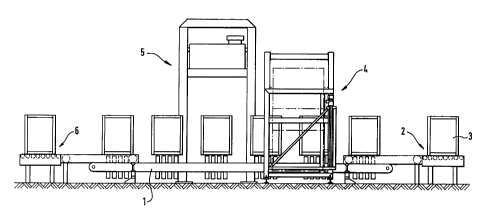
In FIGS. 1 and 2 one can see a conveyor 1 with a
receiving end two for receiving stacked-good units 3 which can be
comprised, especially of pelletized stacks of goods. The
conveyor 1 extends through an apparatus 4 for wrapping the
stacked-goods unit 3 with a shrink foil wrap and further through
a shrink machine 5 of conventional construction up to a discharge
end 6. In the region of the receiving end two, there is provided
a circuitry closet 7.
CA 02298949 2000-02-18
The apparatus 4 for wrapping includes, as is visible
from FIGS. 3 through 9, a frame 9 which forms a portal 8 through
which the party not shown conveyor 1 extends. On exterior sides
of the frame 9, journals 10, 10a for rotatably supporting the
shrink foil rolls having not been shown in FIGS. 4 and 7 for
clarity of the drawing. In the embodiment shown in the FIGURES,
on each side of the frame 9 a respective two shrink foil rolls
11, lla with horizontally extending axes are arranged.
The foil webs 12, 12a withdrawn from the shrink foil
rolls 11, lla pass initially through a foil storage 13, 13a
corresponding to FIGS. 3 and 8, which have at lease one dancer
roll 14, 14a and are guided then respectively over a rerouting
device 15, 15a which in the configuration illustrated, is
comprised of an inclined roller or rail, especially Teflon coated
or completely of Teflon, which guides the foil web 12, 12a from
its horizon orientation into a vertical orientation. In this
vertical orientation, the foil webs coming from both sides at 12,
12a are connected together in the region of the portal 8 at their
respective ends. For this purpose, on both sides of the portal
8, doubled welled beams 16, 16a are disposed which are movable
against one another as associated drives.
Each shrink foil roller 11, 11a has a friction wheel
drive 17, 17a engageable with its periphery.
The illustrated apparatus works as follows:
In the portal 8 the foil webs 12, 12a form with their
ends respectively a shrink foil curtain. Into the shrink foil
curtain, a stacked-goods unit 3 is fed on the conveyor 1 and
6
CA 02298949 2000-02-18
entrains the shrink foil curtain therewith so that the stacked-
good unit 3 is lines on three sides with foil. After the stack-
good unit 3 is positioned by forward or reverse travel, the two
double welled beams 16, 16a arranged on both sides of the
conveyor 1 are displaced together and guide the foil webs 12 and
12a around the rear fourth side of the stacked-good unit 3 until
they meet approximately in the middle or outside of the middle.
There the two foil webs 12, 12a are provided with a double welled
seam and are separated by a hot wire not shown in the middle
between the double welled seam, so that for the following
stacked-good unit 3 a further shrink foil curtain is provided.
The friction wheel drives 17, 17a of the shrink foil
rolls 11, lla can operate independently of the transport speed of
the conveyor 1 and of the cycling rate of the apparatus
practically without interruption so that the foil webs 12, 12a
are fed continuously into the respective foil storages 13, 13a.
The foil webs in the foil storages 13, 13a are withdrawn
therefrom as need arises, i.e. when a new stacked goods unit 3 is
fed into the portal 8 and thus entrains the shrink foil curtain
there found with that stacked-goods unit 3.
When a shank foil roller 11, lla is consumed, initially
without replacement of the shrink foil rolls 11, 11a, the other
shrink roil rolls 11, 11a are set in operation. One can,
however, also provide at each side of the frame 9 shrink foil
rolls 11, lla with different foil widths and thus provides the
possibility for a rapid change of foil widths.
7
CA 02298949 2000-02-18
As has been shown in FIGS. 7 through 9, the inactive
foil curtain is then guided upwardly. The path difference
resulting from the upward movement between the shrink foil
curtain and the shrink foil curtain roll 11, lla is compensated
via the dancer rolls 14, 14a in the foil storage 13, 13a.
The second shrink foil curtain can, however, arrange
overlapping with the first shrink foil curtain when stacked-goods
units 3 are to be wrapped which have heights greater than the
height of one shrink foil curtain.
In this case, the rerouting devices 15, 15a are
displaced into their higher positions whereby the foil storages
13, 13a compensates the path change. It is possible to displace
only one pair of shrink foil rollers 11a corresponding to FIGS. 7
through 9, although it is also possible to change a plurality of
pairs of shrink-foil rollers 11, lla as to their positions.
According to FIG. 8, for the total height of the
stacked-goods unit 3 only one pair of double welled beams 16 is
provided for the simultaneous welding of all shrink foils
although the embodiment of FIG. 9 has two pairs of double welled
beams 16, 16a which weld the various foil webs 12, 12a one after
the other.
8