Language selection

Search

Patent 2299842 Summary

Third-party information liability

Some of the information on this Web page has been provided by external sources. The Government of Canada is not responsible for the accuracy, reliability or currency of the information supplied by external sources. Users wishing to rely upon this information should consult directly with the source of the information. Content provided by external sources is not subject to official languages, privacy and accessibility requirements.

Claims and Abstract availability

Any discrepancies in the text and image of the Claims and Abstract are due to differing posting times. Text of the Claims and Abstract are posted:

  • At the time the application is open to public inspection;
  • At the time of issue of the patent (grant).
(12) Patent: (11) CA 2299842
(54) English Title: ARTICLE WITH INTERLOCKING EDGES AND COVERING PRODUCT PREPARED THEREFROM
(54) French Title: ARTICLES A BORDURES A EMBOITEMENT ET REVETEMENTS PREPARES AVEC CES ARTICLES
Status: Deemed expired
Bibliographic Data
(51) International Patent Classification (IPC):
  • F16S 1/02 (2006.01)
  • E04C 2/00 (2006.01)
  • E04F 15/00 (2006.01)
  • E04F 15/04 (2006.01)
(72) Inventors :
  • NELSON, THOMAS JOHN (United States of America)
(73) Owners :
  • PREMARK RWP HOLDINGS, INC. (United States of America)
(71) Applicants :
  • PREMARK RWP HOLDINGS, INC. (United States of America)
(74) Agent: GOWLING WLG (CANADA) LLP
(74) Associate agent:
(45) Issued: 2005-05-24
(22) Filed Date: 2000-03-02
(41) Open to Public Inspection: 2000-10-12
Examination requested: 2000-03-02
Availability of licence: N/A
(25) Language of filing: English

Patent Cooperation Treaty (PCT): No

(30) Application Priority Data:
Application No. Country/Territory Date
09/291,587 United States of America 1999-04-12

Abstracts

English Abstract


An article is provided that is suitable for use in surface coverings, such as
laminate
floorings, wherein the article has at least one interlocking edge of a first
profile and at least one
interlocking edge of a second profile, the interlocking edges providing the
ability to interlock
adjacent articles without the need for an adhesive, and yet forming a
substantially gapless seam
between the articles. The articles may be joined and enjoined from each other
a plurality of
times without any substantial deterioration of the interlocking edge profiles.


Claims

Note: Claims are shown in the official language in which they were submitted.


THE EMBODIMENTS OF THE INVENTION IN WHICH AN EXCLUSIVE PROPERTY
OR PRIVILEGE IS CLAIMED ARE DEFINED AS FOLLOWS:

1. An article having interlocking edges comprising:
an upper planar surface;
a lower planar surface;
a male edge;
a female edge;
said male edge and said female edge positioned on opposite sides of said
article; said male edge capable of joining with said female edge of an
adjacent
matching article;
said male edge and said female edge having a planar index surface
respectively each being at a same distance from said upper planar surface;
said male edge having a lower first female member defined by said planar
index surface and a downward and outward surface and an upper first female
member;
said male edge having a first male member defined by a first lower surface
forming an angle with said planar index surface, and located between the lower
first
female member and the upper first female member;
said female edge having a lower second male member defined by said planar
index surface and an upward and outward facing surface, said lower second male
member being complementary to said lower first female member; an upper second
male member; and
a second female member including a downward and outward facing surface
being complementary with said first lower surface of said male edge; said
second
female member located between said lower second male member and said upper
second male member;
whereby said article can be joined together with an adjacent article of like
construction by aligning said upper planar surfaces and said lower planar
surfaces

14


being coplanar and by pushing said two pieces together to engage the
complimentary
profiles of said male edge and said female edge into place and form a
substantially
gapless seam.

2. The article as recited in Claim 1 wherein said article is a laminated
glueless
interlocking floor panel, a decorative laminate being laminated and secured on
a core
material for said article.

3. The article as recited in Claim 1 wherein said core material is a
fiberboard.

4. A rectilinear surfacing article comprising:
substantially planar surfaces including an upper planar surface, a first
interlocking edge having a first profile and a second interlocking edge having
a
second profile, the second profile being complementary to the first profile,
the first
profile comprising a first male member and an upper first female member and a
lower
first female member, wherein the first male member has a first upper surface,
a first
lower surface, one of the first upper surface and the first lower surface at
an angle
with respect to said upper planar surface, and a first notched surface at a
distal end
thereof, and the second profile comprising a second female member; an upper
second
male member including a downwardly and outwardly facing surface having a
second
notched surface at a convex distal end thereof, and a lower second male
member, the
first notched surface and the second notched surface being oriented for
engagement as
first and second profiles of two adjacent articles approach one another;
the upper first female member being located between the upper surface and a
proximal end of the first male member, and the upper second male member being
located between the upper surface and the second female member;
wherein the first interlocking edge and the second interlocking edge of an
adjacent article of like construction can be joined by a process comprising:
causing the first interlocking edge and the second interlocking edge to
approach one another at the notched surfaces, such that the second notched
surface ramps up onto the first notched surface until such a time that the
second notched surface rides over the first notched surface and the upper
second male member enters the upper first female member; and
engaging the complementary profiles of the articles;

15


to form a substantially gapless seam having a longitudinal direction, wherein
the articles cannot be separated by a tensile force applied in the plane of
the articles
and substantially perpendicular to the longitudinal direction of the seam
without
breaking at least one of the interlocking edges, wherein engagement of the
complementary profiles further forms a rotatable joint comprising the convex
distal
end of the upper second male member being sealed into the upper first female
member, the rotatable joint being amenable to rotation about the seam when
under
pressure from above.

5. A rectilinear surfacing article comprising:
substantially planar surfaces including an upper planar surface and a lower
planar surface, the upper planar surface and the lower planar surface being
formed by
laminating a surfacing material onto a central core, a first interlocking edge
having a
first profile and a second interlocking edge having a second profile, the
second profile
being complementary to the first profile, the first profile comprising a first
male
member and an upper first female member and a lower first female member,
wherein
the first male member has a first upper surface and a first lower surface, one
of the
first upper surface and the first lower surface at an angle with respect to
said upper
planar surface, and the second profile comprising a second female member, an
upper
second male member, and a lower second male member;
wherein the first interlocking edge and the second interlocking edge of an
adjacent article of like construction can be joined by a process comprising:
causing the first interlocking edge and the second interlocking edge to
approach one another at an angle a, wherein a represents an angle formed by
the planar surfaces of the two articles;
engaging the complementary profiles of the articles; and
causing the planar surfaces of the two articles to become coplanar;
to form a substantially gapless seam having a longitudinal direction, wherein
the articles cannot be separated by a tensile force applied in the plane of
the articles
and substantially perpendicular to the longitudinal direction of the seam
without
breaking at least one of the interlocking edges, wherein engagement of the
complementary profiles further forms a rotatable joint comprising the convex
distal

16


end of the upper second male member being sealed into the upper first female
member, the rotatable joint being amenable to rotation about the seam when
under
pressure from above.

6. A rectilinear surfacing article comprising:
substantially planar surfaces including an upper planar surface, a first
interlocking edge having a first profile and a second interlocking edge having
a
second profile, the second profile being complementary to the first profile,
the first
profile comprising a first male member and an upper first female member and a
lower
first female member, wherein the first male member has a first upper surface,
a first
lower surface one of the first upper surface and the first lower surface at an
angle with
respect to said upper planar surface, and a first notched surface at a distal
end thereof,
and the second profile comprising a second female member; an upper second male
member including a downwardly and outwardly facing surface having a second
notched surface at a convex distal end thereof, and a lower second male
member, the
first notched surface and the second notched surface being oriented for
engagement as
first and second profiles of two adjacent articles approach one another;
wherein the first interlocking edge and the second interlocking edge of an
adjacent article of like construction can be joined by a process comprising:
causing the first interlocking edge and the second interlocking edge to
approach one another at the notched surfaces, such that the second notched
surface ramps up onto the first notched surface until such a time that the
second notched surface rides over the first notched surface and the upper
second male member enters the upper first female member; and
engaging the complementary profiles of the articles;
to form a substantially gapless seam having a longitudinal direction,
wherein the articles cannot be separated by a tensile force applied in the
plane of
the articles and substantially perpendicular to the longitudinal direction of
the seam
without breaking one of the interlocking edges.

7. A rectilinear floor surfacing article installed over a flexible pad, the
article
comprising:

17


substantially planar surfaces including an upper planar surface, the article
further including a first interlocking edge having a first profile and a
second
interlocking edge having a second profile, the second profile being
complementary to
the first profile, the first profile comprising a first male member and an
upper first
female member and a lower first female member, wherein the first male member
has a
first upper surface and a first lower surface, one of the first upper surface
and the first
lower surface at an angle with respect to said upper planar surface, and the
second
profile comprising a second female member, an upper second male member, and a
lower second male member;
wherein the first interlocking edge and the second interlocking edge of an
adjacent article of like construction can be joined by a process comprising:
causing the first interlocking edge and the second interlocking edge to
approach one another at an angle .alpha., wherein .alpha. represents an angle
formed by
the planar surfaces of the two articles;
engaging the complementary profiles of the articles; and
causing the planar surfaces of the two articles to become coplanar;
to form a substantially gapless seam having a longitudinal direction, wherein
the articles cannot be separated by a tensile force applied in the plane of
the articles
and substantially perpendicular to the longitudinal direction of the seam
without
breaking at least one of the interlocking edges, the seam forming a flexible
joint such
that when weight is applied to the seam the articles rotate slightly about the
joint as
the seam is slightly depressed into a flexible pad, the flexible joint being
constructed
so as to prevent any damage from occurring to the first and second
interlocking edges
as a result of the rotation of the articles.

8. A rectilinear surfacing article comprising:
substantially planar surfaces including an upper planar surface, a first
interlocking edge having a first profile and a second interlocking edge having
a
second profile, the second profile being complementary to the first profile,
the first
profile comprising a first male member and an upper first female member and a
lower
first female member, wherein the first male member has a first upper surface a
first
lower surface, one of the first upper surface and the first lower surface at
an angle

18


with respect to said upper planar surface, and a first notched surface at a
distal end
thereof, and the second profile comprising a second female member; an upper
second
male member including a downwardly and outwardly facing surface having a
second
notched surface at a convex distal end thereof, and a lower second male
member, the
first notched surface and the second notched surface being oriented for
engagement as
first and second profiles of two adjacent articles approach one another;
wherein the first interlocking edge and the second interlocking edge of an
adjacent article of like construction can be joined by a process comprising:
causing a first interlocking edge and a second interlocking edge of
two adjacent articles to approach one another at the notched surfaces, such
that the second notched surface ramps up onto the first notched surface until
such a time that the second notched surface rides over the first notched
surface and the upper second male member enters the upper first female
member; and
engaging the complimentary profiles of the articles;
to form a substantially gapless seam having a longitudinal direction, wherein
the articles cannot be separated by a tensile force applied in the plane of
the articles
and substantially perpendicular to the longitudinal direction of the seam
without
breaking at least one of the interlocking edges, wherein the articles may be
joined and
unjoined a plurality of times without functional deterioration of the first
and second
interlocking edges.

9. A rectilinear surfacing article comprising:
substantially planar surfaces including an upper planar surface and a lower
planar surface, the upper planar surface and the lower planar surface being
formed by
laminating a surfacing material onto a central core, a first interlocking edge
having a
first profile and a second interlocking edge having a second profile, the
second profile
being complementary to the first profile, the first profile comprising a first
male
member and an upper first female member and a lower first female member,
wherein
the first male member has a first upper surface and a first lower surface, one
of the
first upper surface and the first lower surface at an angle with respect to
said upper
planar surface, and the second profile comprising a second female member, an
upper
second male member, and a lower second male member;

19


wherein the first interlocking edge and the second interlocking edge of an
adjacent article of like construction can be joined by a process comprising:
causing the first interlocking edge and the second interlocking edge to
approach one another at an angle .alpha., wherein .alpha. represents an angle
formed by
the planar surfaces of the two articles;
engaging the complementary profiles of the articles; and
causing the planar surfaces of the two articles to become coplanar;
to form a substantially gapless seam having a longitudinal direction, wherein
the articles cannot be separated by a tensile force applied in the plane of
the articles
and substantially perpendicular to the longitudinal direction of the seam
without
breaking at least one of the interlocking edges, wherein the articles may be
joined and
unjoined a plurality of times without functional deterioration of the first
and second
interlocking edges.

10. A rectilinear surfacing article comprising:
substantially planar surfaces including an upper planar surface, a first
interlocking edge having a first profile and a second interlocking edge having
a
second profile, the second profile being complementary to the first profile,
the first
profile comprising a first male member and an upper first female member and a
lower
first female member, wherein the first male member has a first upper surface
and a
first lower surface, one of the first upper surface and the first lower
surface at an angle
with respect to said upper planar surface, and the second profile comprising a
second
female member and an upper second male member and a lower second male member;
the upper first female member being located between the upper surface and a
proximal end of the first male member, and the upper second male member being
located between the upper surface and the second female member, the upper
second
male member having a convex distal end;
wherein the first interlocking edge and the second interlocking edge of an
adjacent article of like construction can be joined by a process comprising:
causing the first interlocking edge and the second interlocking edge to
approach one another at an angle .alpha., wherein .alpha. represents an angle
formed by the
planar surfaces of the two articles;


engaging the complementary profiles of the articles; and
causing the planar surfaces of the two articles to become coplanar;
to form a substantially gapless seam having a longitudinal direction, wherein
the articles cannot be separated by a tensile force applied in the plane of
the articles
and substantially perpendicular to the longitudinal direction of the seam
without
breaking at least one of the interlocking edges, wherein engagement of the
complementary profiles further forms a rotatable joint comprising the convex
distal
end of the upper second male member being seated into the upper first female
member, the rotatable joint being amenable to rotation about the seam when
under
pressure from above.

11. A rectilinear surfacing article comprising:
substantially planar surfaces including an upper planar surface, a first
interlocking edge having a first profile and a second interlocking edge having
a
second profile, the second profile being complementary to the first profile,
the first
profile comprising a first male member and an upper first female member and a
lower
first female member, wherein the first male member has a first upper surface
and a
first lower surface, at an angle with respect to said first upper surface, and
the second
profile comprising a second female member, an upper second male member, and a
lower second male member;
wherein the first interlocking edge and the second interlocking edge of an
adjacent article of like construction can be joined by a process comprising:
causing the first interlocking edge and the second interlocking edge to
approach one another at an angle .alpha., wherein .alpha. represents an angle
formed by the
planar surfaces of the two articles;
engaging the complementary edge profiles of the articles; and
causing the planar surfaces of the two articles to become coplanar;
to form a substantially gapless seam having a longitudinal axis;
the rectilinear surfacing article further comprising a first interlocking end
having a first end profile, a second interlocking end having a second end
profile, the
second end profile being substantially complementary to the first end profile;

21


wherein the first interlocking end of a first article may be engaged with the
second interlocking end of a third article of like construction by a process
comprising:
sliding a first article along the longitudinal axis of a previously
engaged interlocked edge;
engaging the complementary end profiles of the first article and the
third articles to form a substantially gapless end seam.

12. A rectilinear surfacing article comprising:
substantially planar surfaces, a first interlocking edge having a first
profile and
a second interlocking edge having a second profile, the second profile being
complementary to the first profile, the first profile comprising a male member
located
between two female members, and the second profile comprising a female member
located between two male members;
wherein the first interlocking edge and the second interlocking edge of a
second adjacent article of like construction can be joined by a process
comprising:
causing the first interlocking edge and the second interlocking edge of two
adjacent articles to approach one another at an angle a, wherein a represents
an angle
formed by the planar surfaces of the two articles;
engaging the complementary profiles of the articles; and
causing the planar surfaces of the two articles to become coplanar;
to form a substantially gapless seam having a longitudinal direction, wherein
the articles cannot be separated by a tensile force applied in the plane of
the articles
and substantially perpendicular to the longitudinal direction of the seam
without
breaking at least one of the interlocking edges.

13. The rectilinear floor surfacing article according to claim 12, wherein the
seam forms a
flexible joint such that when weight is applied to the seam the articles
rotate slightly
about the joint, the flexible joint being constructed so as to prevent any
damage from
occurring to the first and second interlocking edge as a result of the
rotation of the
articles.

22


Description

Note: Descriptions are shown in the official language in which they were submitted.


CA 02299842 2003-06-04
Case 1 U 17P 1
ARTICLE WITH INTERLOCKING EDGES -
AND 'COVERING PRODUCT PREPARED THEREFROM
to BACKGROUND OF THE ON
Field of the Inver~tio~
The present invention relates to an article having interlocking edges and its
use as a
covering product, particularly useful for covering flat surfaces such as
floors, and most useful .
in preparing a flooring product that 'is easy to install, easy to remove, and
easy to repair.
1s
Discussion of the Back~ound:
In-recent years the use of laminate products.-in the flooring industry as a
replacement
or substitute for traditional wood plank flooring has grown tremendously due
to the
durability and ease of care of the laminate products. However, the laminate
flooring products
20 , currently available often have several disadvantages.
Many conventional laminate floor products have "tongue and groove" edges that
are
machined to fit one into the other. However; the conventional method
for.preparing such
edges provides an interference fit that is glued together, particularly in
"floating floor"
systems. Tn the interference fit type of edge, any glue that is placed in the
cutout portion of
Page 1


CA 02299842 2000-03-02
the edge must be forced out upon insertion of the corresponding edge on an
adjacent piece of
laminate. Gluing floor panels together is time consuming and messy; any glue
that seeps out
onto the floor surface must be cleaned up by the installer. Due to the tight
fit, the fitting
together of the laminate pieces also typically requires pressure and clamps to
hold the pieces
together until the glue in the seams dries. Naturally, the floor cannot be
walked on until the
glue dries and the clamps are removed.
Additionally when the pieces are joined, and the glue is forced out of the
cutout edge,
there is no way to control the direction in which the glue will exit. It can
exit either in an
upwards direction towards the visible surface of the flooring, causing a mess,
or in a
to downwards direction to the surface adjacent the subflooring. Either case
may be detrimental
to both the appearance and function of the resulting floor.
Additionally, for direct gluedown applications glue is placed on the bottom
surface of the
flooring section to adhere it to the subfloor. Once the glue sets, the
resulting floor can be
extremely diffcult or impossible to repair or replace. Additionally, due to
expansion and/or
15 contraction within individual sections of laminate flooring, the resulting
floor can undergo
various stresses causing distortions, buckling, etc., thus rendering the floor
aesthetically
unsightly.
Also, some prior art methods of attaching adjoining flooring panels require
that channels
of significant size be machined into the underside of the flooring panels.
Such a prior art method
2o is described in U.S. Patent No. 5,860,267 by Pervan. This prior art method
requires that the
channels be machined into the underside of the panels a considerable distance
from the panel
edges, and configured so as to accept a separate piece that is connected to
each panel to provide a
Page 2


CA 02299842 2000-03-02
means for attachment of adjacent panels. These channels weaken the panels,
increase
manufacturing cost, and result in more opportunity for panel warpage under the
influence of
moisture.
A new means of attaching individual flooring panels, particularly in the
laminate flooring
arena, is needed to overcome these disadvantages.
SUMMARY OF THE INVENTION
Accordingly, one object of the present invention is to provide a new surface
covering
product that is easy to install, can be installed without glue if desired, is
easy to repair and/or
t o replace, and may be used as soon as it is installed.
A fiurther object of the present invention is to provide a new surface
covering product
having an edge design that can be assembled and disassembled in a simple
manner without
tools or glue.
Another object of the present invention is to provide a surface covering
product that
15 has a substantially hydrophobic interior to provide a watertight seam
between sections.
Another object of the present invention is to provide a laminate flooring
prepared from
the surface covering product of the present invention.
Another object of the present invention is to provide a surface covering
product that can
be used as flooring, wall covering, ceilings and on curved surfaces.
2o Disclosed is a rectilinear surfacing article comprising substantially
planar surfaces. The
article has at least one first interlocking edge having a first profile and at
least one second
interlocking edge having a second profile, the second profile being
complementary to the first
Page 3


CA 02299842 2000-03-02
profile. The first profile includes a male member located between two female
members, and the
second profile includes a female member located between two male members.
Each of the articles may be joined to a second adjacent article of like
construction by
causing a first interlocking edge and a second interlocking edge of two
adjacent articles to
approach one another at an angle a, wherein a represents an angle formed by
the planar surfaces
of the two articles. Next, the complementary profiles of the articles are
engaged. Finally, the
planar surfaces of the two articles are caused to become coplanar to form a
substantially gapless
seam between the adjacent articles. The articles thereafter cannot be
separated by a tensile force
applied in the plane of the articles and substantially perpendicular to the
longitudinal direction of
t o the seam without breaking at least one of the interlocking edges. The
articles may be joined and
enjoined a plurality of times without functional deterioration of the first
and second interlocking
edges.
The rectilinear floor surfacing article may be installed over a flexible pad,
whereby
the seam effectively forms a flexible joint such that when weight is applied
to the seam the
t s articles rotate slightly about the joint as the seam is slightly depressed
into the flexible pad. The
flexible joint is constructed so as to prevent any damage from occurnng to the
first and second
interlocking edges as a result of the rotation of the articles under the
applied weight.
The above mentioned male member of the first profile may be configured to
project
outwardly from the first interlocking edge and upwardly toward the plane of
the upper surface of
2o the articles. The first profile may further include a concavity on the
first interlocking edge
located between the upper surface and a proximal end of the male member of the
first profile.
The second profile may further include an upper male member on the second
interlocking edge
Page 4


CA 02299842 2000-03-02
1
located between the upper surface and the female member of the second profile.
The upper male
member of the second interlocking edge may have a convex distal end.
Engagement of these
complementary profiles forms a rotatable joint wherein the convex distal end
of the upper male
member of the second interlocking edge is seated into the concavity of the
first interlocking edge,
the rotatable joint being amenable to rotation about the seam when under
pressure from above.
Also disclosed is an interlocking end profile configuration, which includes
one first
interlocking end having a first end profile, one second interlocking end
having a second end
profile, the second end profile being substantially complementary to the first
end-profile. The
first end profile includes a male member located between two female members,
and the second
1o end profile includes a female member located between two male members. The
first end profile
includes a notched surface on the first male member which faces upwardly and
outwardly. The
second end profile includes a notched surface on the second upper male member
which faces
downwardly and outwardly.
The first interlocking end of a first article may be engaged with the second
interlocking
15 end of a third article of like construction by sliding a first article
along the longitudinal axis of a
previously engaged interlocked edge seam, engaging the complementary end
profiles of the
articles, and snapping the complementary end profiles together to form a
substantially gapless
end seam.
The planar surfaces of the articles may be formed by laminating a surfacing
material onto
2o a central core. The central core may be made of a material selected from
the group consisting of
fiberboard, solid polymeric materials, and foamed polymeric materials. The
central core may
also be made of a hydrophobic polymer, or a foamed polyvinyl chloride,
polyacrylonitrile-co-
butadiene-co-styrene (ABS), polyamide, or high impact polystyrene (HIPS). The
foamed
Page 5


CA 02299842 2000-03-02
polymeric material has a density reduction of from 0 to 50%. The upper
decorative planar
surface may be high pressure decorative laminate, polymeric surfacing
material, wood veneer, or
any other decorative surfacing material. _
s BRIEF DESCRIPTION OF THE FIGURES
A more complete appreciation of the invention and many of the attendant
advantages
thereof will be readily obtained as the same becomes better understood by
reference to the
following detailed description when considered in connection with the
accomparLying drawings,
wherein:
i o Fig. 1 A shows an embodiment of the interlocking profiles of the side
edges of the present
invention.
Fig. 1B shows preliminary engagement of the interlocking profiles of Fig. IA.
Fig. 1C shows final engagement of the interlocking profiles of Fig. lA.
Fig. 2A shows an embodiment of the interlocking profiles of the end edges of
the present
I S invention.
Fig. 2B shows preliminary engagement of the interlocking profiles of Fig. 2A.
Fig. 2C shows final engagement of the interlocking profiles of Fig. 2A.
Fig. 3A shows engagement of the side edges of adjacent floor panels embodying
the
present invention.
2o Fig. 3B shows engagement of the end edges of adjacent floor panels
embodying.the
present invention.
Fig. 4A shows the side edge interlocking profiles of Fig. 1 G as installed
over a flexible
pad.
Page 6


CA 02299842 2003-06-04
Fig. ~B shows how the embodiment of Fig. 3A reacts when subjected to pressure
from
above.
DETAILED DESCRIPTION OF TF1E PREFERRED EMBODIMENTS
5. The article of the present invention may be made of a uniform material,
such as wood,
plastic, etc., or may comprise a central core having upper and lower surfaces
of a different
material than that of the central core, as well as a plurality of edge
surfaces around its periphery.
The surface layers may be high pressure decorative laminate, solid surfacing
veneer, wood veneer, or solid surfacing laminate; or any other conventional
1 o decorative layer that can be bonded to a central core. Preferably, the
upper surface is a high pressure decorative laminate layer, and the lower
surface is a laminate
backer. The upper and lower surface layers may be the same or different
materials. The
decorative layers can be formed from a variety of materials. Suitable
materials for the decorative
layers include, but ate not limited to, conventional high pressure decorative
laminate (made from
15 melamine formaldehyde impregnated Icraft paper layers), wood veneers, or
conventional
polymeric solid surfacing veneers or laminates. The decorative~layers can be
attached to the core
using conventional means, such as adhesives, or by coextrusion of the core and
decorative layers,
either with or without a tie layer.
Whether or not the core forms the entire article, the core can be prepared
from wood,
2o wood based products such as fiberboard (such as high density fiberboard),
polymeric materials
etc. Suitable polymeric materials include, but are not limited to, rigid
.thermoplastics and
thermosets, as well as more flexible elastomers and rubbers. When the article
of the present
invention is to be used to form a surface covering for a curved surface
(either. concave or
Page 7


CA 02299842 2000-03-02
convex), the article is preferably made from one of these more flexible
materials in order to more
accurately conform to the curved surface.
The core of the present product can be formed from a variety of materials,
such as wood -
or wood based products, plastics, metals, etc. In order to gain the maximum in
waterproofing
and dimensional stability over time, it is preferred to make the central core
from a plastic, more
preferably from a hydrophobic polymer. Suitable hydrophobic polymers include
polyvinyl
chloride, polystyrene, polyolefins, etc. The core is most preferably prepared
from a foamed
hydrophobic polymer, such as an ABS, HIPS, or polyvinyl chloride foam, having
a preferred
density reduction of from 0 to 50%, more preferably from 20 to 40% density
reduction, most
to preferably about 30% density reduction. Within the context of the present
invention, the term
"density reduction" is defined as the percentage by which the density of the
foam is lower than
the density of the unfoamed polymer that comprises the foam. The use of the
hydrophobic
polymer foam of the present invention provides both improved watertight seam
properties as
well as ease of handling due to the lighter weight of the foam.
A polymeric core can be formed by any conventional process, including but not
limited
to, molding, casting, extrusion, etc. When the core is made from a fiberboard
or chipboard
composition, the core can be prepared by any conventional process. When the
article is a solid
piece of wood, the article can be prepared by conventional woodworking
techniques, so long as
the edge profile is prepared to meet the requirements of the invention. The
profile of the edges of
the laminate flooring of the present invention can be formed by routing,
cutting, etc. as needed.
Further, when the core is made from a polymeric material, the profile of the
edges may be made
by cutting, or may be formed by extruding the core with the profiles intact.
Page 8


CA 02299842 2000-03-02
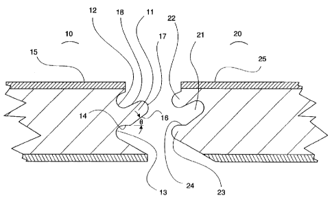
As shown iii Fig. lA, the article of the present invention may have
substantially planar
upper and lower surfaces, with at least one first interlocking edge having a
first profile and at
least one second interlocking edge having a second profile, wherein the first
profile and the _
second profile are complementary to each other and are located on opposing
sides from one
another. The edges are formed such that two articles may be joined together
along the
complementary profiles as shown in Figs. lA-1C, by approaching the first edge
profile of a first
article with the second edge profile of a second article from an angle, a, as
shown in Fig. 1B.
The first profile is incorporated into article 10, and has first male member
11, upper first female
member 12, and lower first female member 13. The second profile is
incorporated into article
20, and has second female member 21, upper second male member 22, and lower
second male
member 23. First male member 11 is slightly tapered toward its distal end to
provide for
unrestricted insertion into female member 21, as shown in Fig. 1B. Once member
11 is
positioned within member 21, article 20 is lowered such that the surfaces of
the two articles 10
and 20 become substantially coplanar. The edge profile of each article is
formed in a pattern
such that upon engagement, as showwin Fig. 1 C, the seam between the two
articles is
substantially gapless. The interlocking is sufficient to prevent separation of
the two adjoining
articles upon application of a tensile force on the articles along a vector
parallel to the surfaces
and perpendicular to the longitudinal direction of the seam, without breaking
one or both of the
edge profiles. The edge profiles are also formed to provide an approach angle
a, as shown in~
2o Fig. 1 B, of from 10 to 45 degrees, preferably from 10 to 20 degrees, most
preferably 1 S - 18
degrees. Although articles 10 and 20 may not be pulled apart as described
above, it is preferable
that the complementary profiles be configured so that an engaged seam allows
the adjoined
Page 9


CA 02299842 2000-03-02
articles 10 and 20 to slide relative to one another in a direction parallel to
the longitudinal axis of
the seam, for reasons that will be described below.
A preferred embodiment would also include first and second end profiles, as
shown on
articles 30 and 40 in Figs. 2A-2C. The end profiles are configured
substantially the same as the
edge profiles shown in Figs. 1 A-1 C, with the exception that the first
profile has upward and
outward facing surface 31 notched into first male member 32 and the second
profile has
downward and outward facing surface 41 notched into upper second male member
42. This
configuration allows these ends to be joined together by sliding article 30,
which has previously
been engaged with adjacent articles along its edge, forward and pushing its
end profile into the
to end profile of article 40 so as to snap the first and second end profiles
together into place.
As surfaces 31 and 41 come toward each other and begin to engage, surface 41
ramps up
onto surface 31. As surface 41 ramps further and fiuther up onto surface 31, a
point is reached
where first point 33 and second point 43 ride up onto and over each other.
This action requires a
given amount of compressive force, both in the horizontal and vertical
directions. Members 32
15 and 42 must flex to some degree to allow points 33 and 43 to ride over each
other, but once this
takes place, members 32 and 42 snap back into their original positions and
articles 30 and 40 are
pulled toward each other. This is due to the fact that point 33 is higher than
point 43, which
causes member 32 to ride up into the cavity under member 42.
Substantially all of the materials used to make the articles of the present
invention have
2o enough flexibility to provide for this snap engagement of the end profiles
described above.
These end profiles also cannot be pulled apart by pulling the pieces in
opposite directions
without breakage of the profiles due to the interlocking configuration of the
profiles.
Page 10


CA 02299842 2000-03-02
Figures 3A and 3B show how a plurality of articles embodying the present
invention
would be put together to form, for example, a floor. Fig. 3A shows how an edge
of an article 50
would be rotatably engaged to adjacent articles 51 and 52, as described above
with respect to
Figs. lA-1C. Fig. 3B shows how an end of an article 50 would be slidably
engaged to an end of
an adjacent article 53, as described above with respect to Figs. 2A-2C.
The profiles shown in Fig. 1 A each have a planar index surface 14 and 24
respectively.
The two planar index surfaces 14 and 24 are each substantially the same
distance from the planar
decorative surfaces 15 and 25. This provides for substantially coplanar
registration of surfaces
1 S and 25 with respect to each other.
1o The remaining description of the edge profile will center on the male edge
of the
preferred embodiment, with the understanding that the female edge is designed
to provide the
ease of construction qualities of the present invention and to be at least
nearly completely exactly
complementary to the male edge profile. Within the context of the present
invention, the term
"nearly completely" indicates that the lower surfaces of the male and female
edges may not form
a completely gapless seam, as shown in the gap 60 of Fig. 1 C. This gap does
not have to be
present but is preferred in order to allow for wear in the cutting tools used
to form the edge
profile, which would otherwise cause a perfectly fitting seam to gradually
force the lower planar
surfaces away from coplanar. With the small gap 60 in the bottom of the edge,
the production
tooling can last longer between changes without detrimentally affecting the
fit of the seam.
2o In the most preferred embodiment of Figs. 1 A-1 C, the first profile has
member 11 above
the planar index surface 14. Between member 11 and planar decorative surface 1
S is first upper
female member 12. Member 11 is angled outwardly and upwardly from planar index
surface 14
towards the plane formed by planar decorative surface 15 such that a first
lower surface 16 of
Page 11


CA 02299842 2000-03-02
member 11 forms an angle A with the planar index surface 14. Angle 8 may be
from 20 to 50
degrees, preferably from 25 to 45 degrees, most preferably from 30 to 40
degrees. Member 11
has a rounded distal end 17 and a first upper surface 18 that is nonparallel
with first lower surface -
16, such that surfaces 16 & 18 result in a slight taper of member 11 toward
distal end 17. First
upper surface 18 of member 11 also forms a lower surface of first upper female
member 12.
Below the planar index surface 14 is first lower female member 13 which has an
upper surface
that corresponds to planar index surface 14. The first and second profiles are
complementary to
the extent that upon engagement of complementary edge and/or end profiles of
adjacent articles,
a seam is formed that is substantially without gaps.
1 o Refernng now to Figs. 4A and 4B, a typical "floating floor" system is
shown. In a
floating floor system, flooring panels are glued together along their edges.
The panels are not
attached in any way to the subfloor. The present invention eliminates the need
for gluing
individual panels together. Subfloor 100 is covered with flexible pad 102.
First panel 104 and
second panel 106 are attached as described above, and are placed directly onto
flexible pad 102.
As shown in Fig. 4B, when pressure is exerted onto seam area 108 the joint
configuration of the
present invention acts like a ball and socket joint thus allowing flexure in a
way that will not
result in wear and breakage associated with the seam joints of the prior art.
Because the
structural integrity of the resulting floor is heavily reliant on seam
integrity, the present invention
results is a floor that is much less likely to fail due to seam failures.
Also, the present invention
2o allows such a floor to be taken apart and put back together many, many
times without wear or
breakage of the seam components.
Page 12


CA 02299842 2000-03-02
Obviously, additional modifications and variations of the present invention
are possible
in light of the above teachings. It is therefore to be understood that within
the scope of the
appended claims, the invention may be practiced otherwise than as specifically
described herein.
Page 13

Representative Drawing
A single figure which represents the drawing illustrating the invention.
Administrative Status

For a clearer understanding of the status of the application/patent presented on this page, the site Disclaimer , as well as the definitions for Patent , Administrative Status , Maintenance Fee  and Payment History  should be consulted.

Administrative Status

Title Date
Forecasted Issue Date 2005-05-24
(22) Filed 2000-03-02
Examination Requested 2000-03-02
(41) Open to Public Inspection 2000-10-12
(45) Issued 2005-05-24
Deemed Expired 2011-03-02

Abandonment History

There is no abandonment history.

Payment History

Fee Type Anniversary Year Due Date Amount Paid Paid Date
Request for Examination $400.00 2000-03-02
Registration of a document - section 124 $100.00 2000-03-02
Application Fee $300.00 2000-03-02
Maintenance Fee - Application - New Act 2 2002-03-04 $100.00 2002-02-21
Maintenance Fee - Application - New Act 3 2003-03-03 $100.00 2003-02-20
Maintenance Fee - Application - New Act 4 2004-03-02 $100.00 2004-02-18
Final Fee $300.00 2005-02-08
Maintenance Fee - Application - New Act 5 2005-03-02 $200.00 2005-02-23
Maintenance Fee - Patent - New Act 6 2006-03-02 $200.00 2006-02-17
Maintenance Fee - Patent - New Act 7 2007-03-02 $200.00 2007-02-19
Maintenance Fee - Patent - New Act 8 2008-03-03 $200.00 2008-02-18
Maintenance Fee - Patent - New Act 9 2009-03-02 $200.00 2009-02-17
Owners on Record

Note: Records showing the ownership history in alphabetical order.

Current Owners on Record
PREMARK RWP HOLDINGS, INC.
Past Owners on Record
NELSON, THOMAS JOHN
Past Owners that do not appear in the "Owners on Record" listing will appear in other documentation within the application.
Documents

To view selected files, please enter reCAPTCHA code :


To view images, click a link in the Document Description column. To download the documents, select one or more checkboxes in the first column and then click the "Download Selected in PDF format (Zip Archive)" or the "Download Selected as Single PDF" button.

List of published and non-published patent-specific documents on the CPD .

If you have any difficulty accessing content, you can call the Client Service Centre at 1-866-997-1936 or send them an e-mail at CIPO Client Service Centre.


Document
Description 
Date
(yyyy-mm-dd) 
Number of pages   Size of Image (KB) 
Drawings 2000-03-02 6 146
Claims 2000-03-02 9 363
Claims 2004-09-09 9 475
Abstract 2000-03-02 1 16
Representative Drawing 2000-10-10 1 9
Claims 2003-06-04 9 476
Description 2003-06-04 13 552
Description 2000-03-02 13 554
Cover Page 2000-10-10 1 35
Claims 2004-02-04 10 457
Representative Drawing 2005-04-21 1 12
Cover Page 2005-04-21 1 40
Correspondence 2005-02-08 1 33
Prosecution-Amendment 2004-09-09 12 564
Assignment 2000-03-02 5 225
Prosecution-Amendment 2000-05-30 1 38
Prosecution-Amendment 2000-09-13 2 54
Prosecution-Amendment 2003-01-09 2 51
Prosecution-Amendment 2003-06-04 14 675
Prosecution-Amendment 2003-08-26 3 107
Prosecution-Amendment 2004-02-04 13 547
Prosecution-Amendment 2004-03-17 2 66
Prosecution-Amendment 2004-11-18 1 27