Note: Descriptions are shown in the official language in which they were submitted.
CA 02304750 2000-03-21
WO 99/15086 PCTNS98/19465
1. Technical Field
This application relates w a surgical stapling apparatus, and more
particularly, to an articulating mechanism for use with an endoscopic surgical
stapling
apparatus for sequentially applying a plurality of surgical fasteners to body
tissue and
optionally incising fastened tissue.
2. Backeround of Relait.ed Art
Surgical devices wherein tissue is first grasped or clamped between
opposing jaw structure and then joined by surgical fasteners are well known in
the
art. In some instruments a Irnife is provided to cut the tissue which has been
joined
by the fasteners. The fasteners are typically in the form of surgical staples
but two
part polymeric fasteners can also be utilized.
Instruments for this purpose can include two elongated members which
are respectively used to capture or clamp tissue. Typically, one of the
members
carries a staple cartridge which houses a plurality of staples arranged in at
least two
lateral rows while the other member has an anvil that defines a'surface for
forming
the staple legs as the staples are driven from the staple cartridge.
Generally, the
stapling operation is effected by cam bars that travel longitudinally through
the staple
cartridge, with the cam bars acting upon staple pushers to sequentially eject
the
staples from the staple cartridge. A knife can travel between the staple rows
to
longitudinally cut and/or open the staplod tissue between the rows of staples.
Such
instruments are disclosed, for example, in U.S. Pat. No. 3,079,606 and U.S.
Pat.
No. 3,490,675.
A later stapler disclosed in U.S. Pat. No. 3,499,591 applies a double
row of staples on each side of the incision. This is accomplished by providing
a
CA 02304750 2000-03-21
WO 99/15086 PCTNS98/19465
disposable loading unit in which a cam member moves through an elongate guide
path
between two sets of staggered staple carrying grooves. Staple drive members
are
located within the grooves and are positioned in such a manner so as to be
contacted
by the longitudinally moving cam member to effect ejection of the staples from
the
staple cartridge of the disposable loading unit. Other examples of such
staplers are
disclosed in U.S. Patent Nos. 4,429,695 and 5,065,929.
Each of the instrments described above were designed for use in
conventional surgical procedures wherein surgeons have direct manual access to
the
operative site. However, in endoscopic or laparoscopic procedures, surgery is
~ performed through a small incision or through a narrow cannula inserted
through
small entrance wounds in the skin. In order to address the specific needs of
endoscopic and/or laparoscopic surgical procedures, endoscopic surgical
stapling
devices have been developed and are disclosed in, for example, U.S. Pat. Nos.
5,040,715 (Green, et al.); 5,307,976 (Olson, et al.); 5,312,023 (Green, et
al.);
5,318,221 (Green, et al.); 5,326,013 (Green, et al.); and 5,332,142 (Robinson,
et
al. ).
U.S. Surgical, the assignee of the present application, has manufactured
and marketed endoscopic stapling instruments, such as the Multifire ENDO GIA*
30
and Multifire ENDO GIA* 60 instruments, for several years. These instruments
have
provided significant clinical benefits. Nonetheless, improvements are
possible, for
example, by reducing the cost and complexity of manufacture.
Current laparoscopic linear stapling devices are configured to operate
with disposable loading units (U.S. Surgical) and staple cartridges (Ethicon)
of only
one size. For example, individual linear staplers are presently available for
applying
parallel rows of staples measuring 30mm, 45mm and 60mm in length. Thus, during
a normal operation, a surgeon may be required to utilize several different
stapling
_2_
CA 02304750 2000-03-21
WO 99115086 PCT/US98/19465
instruments to perform a single laparoscopic surgical procedure. Such
practices
increase the time, complexity and overall costs associated with laparoscopic
surgical
procedures. In addition, costs are greater in designing and manufacturing
multiple
stapler sizes, as opposed to creating a single, multipurpose stapler.
It would be extremely beneficial to provide a surgical device for use
during laparoscopic and/or endoscopic surgical procedures that can be employed
with
several different sized disposable loading units to reduce the overall costs
associated
with such procedures. It would also be particularly beneficial if the device
could
perform multiple tasks, using disposable loading units of varying size and of
varying
purpose, such as, for example, to staple, clip, cut and/or articulate.
In making improvements or modifications to the current instruments, it
would be highly desirable not to sacrifice any of the important benefits of
the
MULTIFIRE ENDO GIA* 30 and 60 instruments as compared to other commercially
available products, e.g., the endoscopic stapling instruments manufactured and
marketed by Ethicon, Inc. For example, any improvement should advantageously
provide a fresh knife blade for each firing of the instrument and ensure that
the
disposable loading unit is securely retained in the stapling instrument unless
and until
the operating team chooses to remove it. These advantages have historically
been
found in the U.S. Surgical instruments, but not in the Ethicon instruments.
In accordance with the present disclosure, a surgical stapling apparatus
for sequentially applying a plurality of fasteners to body tissue and
simultaneously
incising tissue is provided. The surgical stapling apparatus is adapted to
receive
disposable loading units having rows of staples having a linear length of
between
-3-
CA 02304750 2000-03-21
WO 99/15086 PCTNS98/19465
30mm and t50mm. The surgical stapling apparatus is also adapted to receive
articulating and non-articulating disposable loading units.
The surgical stapling apparatus includes a handle assembly having a
movable handle and a stationary handle. The movable handle is movable through
an
actuation stroke to clamp tissue and to effect ejection of staples from the
disposable
loading unit. An elongated body extends distally from the handle assembly and
defines a longitudinal axis. An actuation shaft having a toothed rack is
operably
associated with the movable handle by a pawl mechanism. The distal end of the
actuation shaft is connected to a control rod having a distal end adapted to
operatively
engage an axial drive assembly located within a disposable loading unit.
The stapling apparatus includes an articulation mechanism having an
articulation lever operatively engaged with a cam member having a stepped
caroming
channel. The cam member is engaged with a translation member which includes a
pin dimensioned to be received within the stepped caroming channel such that
pivotable movement of the lever causes linear movement of the translation
member.
A first articulation link includes a proximal end adapted to engage the
translation
member and a distal end adapted to engage a second articulation link
positioned
within the disposable loading unit. Linear movement of the translation member
causes linear movement of the articulation links to cause articulation of a
tool
Z0 assembly of the disposable loading unit.
The surgical stapling apparatus also preferably includes a sensing
mechanism for sensing the type of disposable loading unit secured to the
elongated
body of the apparatus. The sensing mechanism includes a sensing tube
positioned
within the elongated body to engage a disposable loading unit secured to the
elongated
body. A sensing cylinder connected to the sensing tube engages a locking ring
having
a tab portion configured to engage the articulation mechanism in a first
position to
-4-
CA 02304750 2000-03-21
WO 99/15086 PCT/US98/19465
prevent movement of the articulation lever. 1fie locking ring is moved by the
sensing
cylinder when an articulating disposable loading unit is secured to the
elongated body
of the stapling apparatus to a second position to disengage the tab portion
from the
articulation mechanism to permit movement of the articulation lever. In
contrast, a
non-articulating disposable loading unit will not unlock the articulation
lever.
»F DESCIZIprrnnr nF Tr~~ n~~ _w~~~
Various preferred embodiments are described herein with reference to
the drawings:
FIG. 1 is a perspective view of one preferred embodiment of the
presently disclosed surgical stapling apparatus;
FIG. 2 is a top view of the surgical apparatus shown in FIG. 1;
FIG. 3 is a side view of the surgical apparatus shown in FIG. 1;
FIG. 4 is a perspective view with parts separated of the handle
assembly of the surgical apparatus shown in FIG. 1;
FIG. 5 is a cross-sectional view of a portion of the firing lockout
mechanism shown in FIG. 4;
FIG. 6 is a perspective of the slide plate of the anti-reverse clutch
mechanism of the surgical apparatus;
FIG. 7 is an enlarged perspective view of the ants- reverse clutch
mechanism shown in FIG. 1;
FIG. 8 is a side cross-sectional view of the surgical stapling apparatus
shown in FIG. 1 in the non-actuated position with the disposable loading unit
removed;
-5-
CA 02304750 2000-03-21
WO 99/15086 PCTNS98/19465
FIG. 9 is a perspective view with parts separated of the rotation
member, the articulation mechanism, and the elongated body of the surgical
stapling
apparatus shown in FIG. 1;
FIG. 10 is an enlarged view of the indicated area of detail shown in
FIG. 8;
FIG. 10a is a perspective view of the translation member of the
articulating mechanism and the proximal end of the elongated body of the
surgical
stapling apparatus shown in F1G. 1;
FIG. lOb is an enlarged cross-sectional view of the indicated area of
detail of FIG. 8;
FIG. lOc is a cross-sectional view along section line lOc-lOc of FIG. 8;
FIG. 11 is a perspective view of the cam member of the articulation
mechanism of the surgical stapling apparatus shown in FIG. 1;
FIG. 12 is a top view of the cam member of the articulation mechanism
of the surgical stapling apparatus shown in FIG. 1;
FIG. /2a is a perspective view of a non-articulating disposable loading
unit usable with the surgical stapling apparatus shown in FIG. 1;
FIG. 12b is a perspective view of the preferred articulating disposable
loading unit of the surgical stapling apparatus shown in FIG. 1;
FIG. 13 is a cross-sectional view taken along section line 13-13 of FIG.
10;
FIG. 14 is a cross-sectional view taken along section line 14-14 of FIG.
10;
FIG. 15 is a cross-sxtional view taken along section lint 15-15 of FIG.
10;
-6-
CA 02304750 2000-03-21
WO 99/15086 PCT/US98/19465
FIG. 16 is an enlarged view of the indicated area of detail shown in
FIG. 8;
FIG. 17 is a side perspective view of the blocking plate of the surgical
stapling apparatus shown in FIG. 1;
F1G. 18 is a top perspective view of the blocking plate of the surgical
stapling apparatus shown in F1G. 1;
FIG. 19 is a perspective view of a disposable loading unit usable with
the surgical stapling apparatus of FIG. 1;
FIG. 20 is another perspective view of a disposable loading unit usable
with the surgical stapling apparatus of FIG. 1;
FIG. 21 is a perspective view of the tool assembly of the surgical
stapling apparatus of FIG. 1 with parts separated;
FIG. 22 is an enlarged perspective view of the distal end of the anvil
assembly showing a plurality of staple deforming cavities;
FIG. 23 is an enlarged perspective view of the distal end of the staple
cartridge of the surgical stapling apparatus shown in FIG. 1;
FIG. 24 is a side cross-sectional view taken along section line 24-24 of
FIG. 23;
FIG. 25 is a bottom perspective view of the staple cartridge shown in
FIG. 21;
FIG. 26 is an enlarged perspective view of the actuation sled, the
pushers and the fasteners shown in FIG. 21;
FIG. 27 is an enlarged perspective view with parts separated of the
proximal housing portion and mounting assembly of the disposable loading unit
shown
in FIG. 19;
_7_
CA 02304750 2000-03-21
WO 99/15086 PCT/US98/19465
FIG. 28 is an enlarged perspective view of the mounting assembly of
the disposable loading unit shown in FIG. 19 mounted to a distal end portion
of the
proximal housing portion;
FIG. 29 is an enlarged perspective view of the proximal housing
portion and the mounting assembly of the disposable loading unit shown in FIG.
19
with the upper housing half removed;
FIG. 30 is a perspective view of the proximal housing portion and the
mounting assembly of the disposable loading unit shown in FIG. 19 with the
upper
housing half removed;
FIG. 31 is a perspective view with parts separated of the axial drive
assembly;
FIG. 32 is an enlarged perspective view of the axial drive assembly
shown in FIG. 31;
FIG. 33 is an enlarged perspective view of the proumal end of the
IS axial drive assembly shown in FIG. 31 including the locking device;
FIG. 34 is an enlarged perspective view of the distal end of the axial
drive assembly shown in FIG. 31;
FIG. 35 is an enlarged perspective view of the distal end of the
elongated body of the stapling apparatus shown in FIG. 1;
FIG. 36 is an enlarged perspective view of the locking device shown in
FIG. 33;
FIG. 37 is an enlarged perspective view of a lower housing half of the
proximal housing portion of the disposable loading unit shown in FIG. 27;
FIG. 38 is a side cross-sectional view of the disposable loading unit
shown in FIG. 20;
_g_
CA 02304750 2000-03-21
WO 99/1508b PCT/US98/19465
FIG. 39 is an enlarged view of the indicated area of detail shown in
FIG. 38;
FIG. 40 is a perspective view of the surgical stapling apparatus shown
in FIG. 1 with the disposable loading unit of FIG. 19 detached from the
elongated
body;
FIG. 41 is an enlarged perspective view of the disposable loading unit
of FIG. 19 during attachment to the elongated body of the surgical stapling
apparatus
shown in FIG. 1;
FIG. 42 is another enlarged perspective view of the disposable loading
unit of FIG. 19 during attachment to the elongated body of the surgical
stapling
apparatus shown in FIG. 1;
FIG. 43 is a cross-sectional view taken along section line 43-43 of FIG.
41;
FIG. 43a is a side cross-sectional view of the rotation knob, articulation
mechanism, and sensing mechanism during insertion of a disposable loading unit
into
the elongated body of the surgical stapling apparatus;
FIG. 44 is a cross-sectional view taken along section line 44-44 of FIG.
42;
FIG. 45 is a side cross-sectional view of the distal end of the disposable
loading unit of FIG. 1 with tissue positioned between the anvil and clamp
assemblies;
FIG. 46 is a side cross-sectional view of the handle assembly with the
movable handle in an actuated position;
FIG. 47 is an enlarged view of the indicated area of detail shown in
FIG. 46;
FIG. 48 is a cross-sectional view of the proximal end of the disposable
loading unit of FIG. 19 and the distal end of the elongated body of the
surgical
_g_
CA 02304750 2000-03-21
WO 99/15086 PCT/US98/19465
stapling apparatus shown in FIG. 1 with the control rod in a partially
advanced
position;
FIG. 49 is a cross-sectional view of the tool assembly of the surgical
stapling apparatus shown in FIG. 1 positioned about tissue in the clamped
position;
FIG. 50 is a cross-sectional view of the handle assembly of the stapling
apparatus of FIG. 1 during the clamping stroke of the apparatus;
FIG. 31 is a side cross-sectional view of the distal end of the tool
assembly of the stapling apparatus shown in FIG. I during firing of the
apparatus;
FIG. 52 is a side cross-sectional view of the distal end of the tool
IO assembly of the stapling apparatus shown in FIG. 1 after firing of the
apparatus;
FIG. 53 is a side cross-sectional view of the handle assembly of the
apparatus during retraction of the actuation shaft;
FIG. 54 is a side cross-sectional view of the handle assembly of the
stapling apparatus during actuation of the emergency release button;
15 FIG. 55 is a top view of the articulation mechanism of the surgical
stapling apparatus;
FIG. 56 is a side cross-sectional view of the articulation mechanism
and rotation member of the surgical stapling apparatus shown in FIG. 1;
FIG. 57 is a top view of the distal end of the elongated body, the
20 mounting assembly, and the proximal end of the tool assembly during
articulation of
the stapling apparatus;
FIG. 58 is a perspective view of the surgical stapling apparatus during
articulation of the tool assembly;
FIG. 59 is a perspective view of the surgical stapling apparatus during
25 articulation and rotation of the tool assembly;
- 10-
CA 02304750 2000-03-21
WO 99/15086 PCT/US98/19465
FIG. 60 is a top view of the distal and of the disposable loading unit
immediately prior to articulation;
FIG. 61 is a top view of the distal end of the elongated body, the
mounting assembly, and the proximal end of the tool assembly during
articulation of
the stapling apparatus;
FIG. 62 is a partial cross-sectional view of a portion of the disposable
loading unit during retraction of the locking devict; and
FIG. 63 is a partial cross-sectional view of a portion of the disposable
loading unit with the locking device in the lockod position.
DETAILED DESCRIPTION OF FFF'RltFl~ FMRpDFy~,wrrc
Preferred embodiments of the presently disclosed endoscopic surgical
stapling apparatus will now be described in detail with reference to the
drawings, in
which like reference numerals designate identical or corresponding elements in
each
of the several views.
In the drawings and in the description that follows, the term
"proximal", as is traditional, will refer to the end of the stapling apparatus
which is
closest to the operator, while the term distal will refer to the end of the
apparatus
which is furthest from the operator.
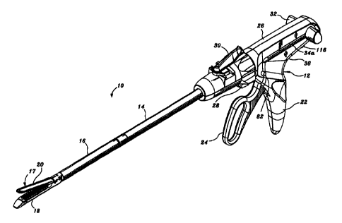
FIGS. 1-3 illustrate one embodiment of the presently disclosed surgical
stapling apparatus shown generally as 10. Briefly, surgical stapling apparatus
10
includes a handle assembly 12 and an elongated body 14. A disposable loading
unit
or DLU 16 is releasably secured to a distal and ~of elongated body 14.
Disposable
loading unit lfi includes a tool assembly 17 having a cartridge assembly 18
housing a
plurality of surgical staples and an anvil assembly 20 movably secured in
relation to
cartridge assembly 18. Disposable loading unit 16 is configured to apply
linear rows
-11-
CA 02304750 2000-03-21
WO 99/15086 PCT/US98/19465
of staples measuring from about 30mm to about 60mm in length. Disposable
loading
units having linear rows of staples of other lengths are also envisioned,
e.g., 45mm.
Handle assembly 12 includes a stationary handle member 22, a movable handle
member 24, and a barrel portion 26. A rotatable member 28 is preferably
mounted
on the forward end of barrel portion 26 to facilitate rotation of elongated
body 14
with respect to handle assembly 12. An articulation lever 30 is also
preferably
mounted on the forward end of barrel portion 26 adjacent rotatable knob 28 to
facilitate articulation of tool assembly 17. A pair of retraction knobs 32 are
movably
positioned along barrel portion 26 to return surgical stapling apparatus 10 to
a
retracted position, as will be described in detail below.
Referring to FIG. 4, handle assembly 12 includes housing 36, which is
preferably formed from molded housing half sections 36a and 36b, which forms
stationary handle member 22 and barrel portion 26 of handle assembly 12 (See
FIG.
1). Movable handle member 24 is pivotably supported between housing half
sections
36a and 36b about pivot pin 38. A biasing member 40, which is preferably a
torsion
spring, biases movable handle 24 away from stationary handle 22. An actuation
shaft
46 is supported within barrel portion 26 of housing 36 and includes a toothed
rack 48.
A driving pawl 42 having a rack engagement finger 43 with laterally extending
wings
43a and 43b is pivotably mounted to one end of movable handle 24 about a pivot
pin
44. A biasing member 50, which is also preferably a torsion spring, is
positioned to
urge engagement finger 43 of driving pawl 42 towards toothed rack 48 of
actuation
shaft 46. Movable handle 24 is pivotable to move engagement finger 43 of
driving
pawl 42 into contact with toothed rack 48 of actuation shaft 46 to advance the
actuation shaft linearly in the distal direction. The forward end of actuation
shaft 46
rotatably receives the proximal end 49 of a control rod 52 such that linear
advancement of actuation shaft 46 causes corresponding linear advancement of
control
-12-
CA 02304750 2000-03-21
WO 99/15086 PCT/US98/19465 _
rod 52. A locking pawl 54 having a rack engagement member 55 is pivotably
mounted within housing 36 about pivot pin 57 and is biased towards toothed
rack 48
by biasing member 56, which is also preferably a torsion spring. Engagement
member 55 of locking pawl 54 is movable into engagement with toothed rack 48
to
retain actuation shaft 46 in a longitudinally fized position.
A retraction mechanism 58 which includes a pair of retractor knobs 32
(See FIG. 1 ) is connected to the proximal end of actuation shaft 46 by a
coupling rod
60. Coupling rod 60 includes right and left engagement portions 62a and 62b
for
receiving retractor knobs 32 and a central portion 62c which is dimensioned
and
configured to translate within a pair of longitudinal slots 34a formed in
actuation shaft
46 adjacent the proximal end thereof. A release plate 64 is operatively
associated
with actuation shaft 46 and is mounted for movement with respect thereto in
response
to manipulation of retractor knobs 32. A pair of spactd apart pins 66 eztend
outwardly from a lateral face of actuation shaft 46 to engage a pair of
corresponding
angled cam slots 68 formed in release plate 64. Upon rearward movement of
retractor knobs 32, pins 66 can release plate 64 downwardly with respect to
actuation
shaft 46 and with respect to toothed rack 48 such that the bottom portion of
release
plate 64 extends below toothed rack 48 to disengage engagement finger 43 of
driving
pawl 42 from toothed rack 48. A transverse slot 70 is formed at the proximal
end of
release plate 64 to accommodate the central portion 62c of coupling rod 60,
and
elongated slots 34 (See FIG. 1) are defined in the barrel section 26 of handle
assembly 12 to accommodate the longitudinal translation of coupling rod 60 as
retraction knobs 32 are pulled rearwardly to retract actuation shaft 46 and
thus retract
control rod 52 rearwardly. Actuation shaft 46 is biased prozimally by spring
72
which is secured at one end to coupling rod portion 62 via connector 74 and at
the
other end to post 76 on actuation shaft 46.
-13-
CA 02304750 2000-03-21
WO 99/15086 PCT/US98/19465 _
Referring also to FIG. 5, handle assembly 12 includes a firing lockout
assembly 80 which includes a plunger 82 and a pivotable locking member 83.
Plunger 82 is biased to a central position by biasing springs 84 and includes
annular
tapered caroming surfaces 85. Each end of plunger 82 extends through housing
36
(See FIG. 1) adjacent an upper end of stationary handle 22. Pivotable locking
member 83 is pivotably attached at its distal end between housing half
sections 36a
and 36b about pivot pin 86 and includes a locking surface 88 and proximal
extension
90 having a slot 89 formed therein. Locking member 83 is biased by spring 92
counter-clockwise (as viewed in FIG. 4) to move locking surface 88 to a
position to
abut the distal end of actuation shaft 46 to prevent advancement of shaft 46
and
subsequent firing of stapling apparatus 10. Annular tapenxl caroming surface
85 is
positioned to extend into tapered slot 89 in proximal extension 90. Lateral
movement
of plunger 82 in either direction against the bias of either spring 84 moves
tapered
caroming surface 85 into engagement with the sidewalls of tapered slot 89 to
pivot
IS locking member 83 clockwise about pivot pin 86, as viewed in FIG. 4, to
move
blocking surface 88 to a position to permit advancement of actuation shaft 46
and thus
firing of stapling apparatus 10. Blocking surface 88 is retained in this
position by
recesses 87 which receive the tapered tip of caroming surface 85 to lock
locking
member 83 in a counter-clockwise position. Operation of firing lockout
assembly 80
will be further illustrated below.
Referring to FIGS. 4, 6, and 7, handle mechanism 12 also includes an
anti-reverse clutch mechanism which includes a first gear 94 mtatably mounted
on a
first shaft 96, and second gear 98 mounted on a second shaft 100, and a slide
plate
102 (FIGS. 6 and 7) slidably mounted within housing 36. Slide plate 102
includes an
elongated slot 104 dimensioned and configured to be slidably positioned about
locking
pawl pivot pin 57, a gear plate 106 configured to mesh with the teeth of
second gear
-14-
CA 02304750 2000-03-21
WO 99/15086 PCT/US98/19465 _
98, and a cam surface 108. In the retracted position, cam surface 108 of slide
plate
102 engages locking pawl 54 to prevent locking pawl 54 from engaging toothed
rack
48. Actuation shaft 46 includes a distal set of gear teeth 110a spactd from a
proximal
set of gear teeth 110b positioned to engage first gear 94 of actuation shaft
46 during
movement of actuation shaft 46. When actuation shaft 46 is advanced by
pivoting
movable handle 24 about pivot pin 38, distal gear teeth 110a on actuation
shaft 46
mesh with and rotate first gear 94 and first shaft 96. First shaft 96 is
connected to
second shaft 100 by spring clutch assembly such that rotation of first shaft
96 will
cause corresponding rotation of second shaft 100. Rotation of second shaft 100
causes corresponding rotation of second gear 98 which is engaged with gear
plate 106
on slide plate 102 to cause linear advancement of slide plate 102. Linear
advancement of slide plate 102 is limited to the length of elongated slot 104.
When
slide plate has been advanced the length of slot 104, cam surface 108 releases
locking
pawl 54 such that it is moved into engagement with toothed rack 48. Continued
advancement of actuation shaft 46 eventually moves gear teeth 110b into
engagement
with gear plate 106. However, since slide plate 102 is longitudinally fixed in
position, the spring clutch is forced to release, such that continued distal
advancement
of actuation shaft 46 is permitted.
When actuation shaft 46 is returned to the retracted position (by pulling
retraction knobs 34 proximally, as discussed above) gear teeth 110b engage
first gear
94 to rotate second gear 98 in the reverse direction to retract slide member
102
proximally within housing 36. Proximal movement of slide member 102 advances
cam surface 108 into locking pawl 54 prior to engagement between locking pawl
54
and toothed rack 48 to urge locking pawl 54 to a position to permit retraction
of
actuation shaft 46.
-15-
CA 02304750 2000-03-21
WO 99/15086 PCT/US98/19465 _
Referring again to FIG. 4, handle asxmbly 12 includes an emergency
return button 112 pivotally mounted within housing 36 about a pivot member 114
supported between housing half sections 36a and 36b. Return button 112
includes an
externally positioned member 116 positioned on the pmzimal end of barrel
portion
26. Member 116 is movable about pivot member 114 into engagement with the
proximal end of locking pawl 54 to urge rack engagement member 55 out of
engagement with toothed rack 48 to permit retraction of actuation shaft 46
during the
firing stroke of the stapling apparatus 10. As discusxd above, during the
clamping
portion of advancement of actuation shaft 46, slide plate 102 dixngages pawl
54 from
rack 48 and thus actuation of return button 112 is not necessary to retract
the
actuation shaft 46.
FIG. 8 illustrates the interconnection of elongated body 14 and handle
assembly 12. Referring to FIGS. 8-10, housing 36 includes an annular channel
117
configured to receive an annular rib 118 formed on the proximal end of
rotation
member 28, which is preferably formed from molded half xctions 28a and 28b.
Annular channel 117 and rib 118 permit relative rotation between rotation
member 28
and housing 36. Elongated body 14 includes inner housing 122 and an outer
casing
124. Inner housing 122 is dimensioned to be received within outer casing 124
and
includes an internal bore 126 (FIG. 8) which extends therethrough and is
dimensioned
to slidably receive a first articulation link 123 and control rod S2. The
proximal end
of housing 122 and casing 124 each include a pair of diametrically opposed
openings
130 and 128, respxtively, which are dimensioned to receive radial projections
132
formed on the distal end of rotation member 28. Projections 132 and openings
128
and 130 fixedly secure rotation member 28 and elongated body 14 in relation to
each
other, both longitudinally and rotatably. Rotation of rotation knob 28 with
respect to
- 16-
CA 02304750 2006-05-26
handle assembly 12 thus results in corresponding rotation of elongated body 14
with
respect to handle assembly 12.
An articulation mechanism 120 is supported on rotatable member 28
and includes articulation lever 30, a cam member 136, a translation member
138, and
first articulation link 123 (FIG. 9). Articulation lever 30 is pivotably
mounted about
pivot member 140 which extends outwardly from rotation member 28 and is
preferably formed integrally therewith. A projection 142 extends downwardly
from
articulation lever 30 for engagement with cam member 136.
Referring temporarily to FIGS. 11 and 12, cam member 136 includes a
housing 144 having an elongated slot 146 extending through one side thereof
and a
stepped caroming surface 148 formed in the other side thereof. Each step of
caroming
surface 148 corresponds to a particular degree of articulation of stapling
apparatus 10.
Although five steps are illustrated, fewer or more steps may be provided.
Elongated
slot 146 is confgured to receive projection 142 formed on articulation lever
30.
Housing 144 includes a distal stepped portion 150 and a proximal stepped
portion
152. Proximal stepped portion 152 includes a recess 154.
Referring again to FIGS. 8-10 and also to FIGS. 13-15, translation
member 138 includes a plurality of ridges 156 which are configured to be
slidably
received within grooves 158 formed along the inner walls of rotation member
28.
Engagement between ridges 156 and grooves 158 prevent relative rotation of
rotation
member 28 and translation member 138 while permitting relative linear
movement.
The distal end of translation member 138 includes arm I60 which includes an
opening
162 configured to receive a finger 164 extending from the proximal end of
articulation link 123 (See FIG. 10a). A pin 166 having a housing 168
constructed
. from a non-abrasive material, e.g., *teflon, is secured to translation
member 138 and
dimensioned to be received within stepped ramming surface 148.
-17-
*Trade-mark
CA 02304750 2000-03-21
WO 99/15086 PCT/US98/19465 _
In an assembled condition, proximal and distal stepped portions 150
and 152 of cam member 136 are positioned beneath flanges 170 and 172 formed on
rotation member 28 to restrict cam member 136 to transverse movement with
respect
to the longitudinal axis of stapling apparatus 10. When articulation lever 30
is
pivoted about pivot member 140, cam member 136 is moved transversely on
rotation
member 28 to move stepped caroming surface 148 transversely relative to pin
166,
forcing pin 166 to move proximally or distally along stepped cam surface 148.
Since
pin 166 is fixedly attached to translation member 138, translation member 138
is
moved proximally or distally to effect corresponding proximal or distal
movement of
first actuation link 123.
Referring to FIGS. 8-10 and 16, a disposable loading unit sensing
mechanism extends within stapling apparatus 10 from elongated body 14 into
handle
assembly 12. The sensing mechanism includes a sensor tube 176 which is
slidably
supported within bore 26 of elongated body 14. The distal end of sensor tube
176 is
positioned towards the distal end of elongated body 14 and the proximal end of
sensor
tube 176 is secured within the distal end of a sensor cylinder 176 via a pair
of nubs
180. The distal end of a sensor link 182 is secured to the proximal end of
sensor
cylinder 178. Sensor link 182 (See FIGS. 8a and 8c) has a bulbous end 184
which
engages a caroming surface 83a on pivotable locking member 83. When a
disposable
loading unit (not shown) is inserted in the distal end of elongated body I4,
the
disposable loading unit engages the distal end 177 of sensor tube 176 to drive
sensor
tube 176 proximally, and thereby drive sensor cylinder 178 and sensor link 182
proximally. Movement of sensor link 182 proximally causes bulbous end 184 of
sensor link 182 to move distally of caroming surface 83a to allow locking
member 83
to pivot under the bias of spring 92 from a position permitting firing of
stapling
apparatus 10 to a blocking position, wherein blocking member 83 is positioned
to
- 18-
CA 02304750 2000-03-21
WO 99/15086 PCT/US98/19465 _
engage actuation shaft 46 and prevent firing of stapling apparatus 10. Sensor
link 182
and locking member 83 function to prevent firing of surgical stapling
apparatus 10
after a disposable loading unit has bean secured to elongated body 14, without
first
operating firing lockout assembly 80. It is noted that movement of link 182
proximally permits locking member 83 to move to its position shown in FIG. 5.
Referring again to FIGS. 9-12, cam member 136 includes recess 154.
A locking ring 184 having a nub portion 186 configured to be received within
recess
154 is positioned about sensor cylinder 178 between a control tab portion 188
and a
proximal flange portion 190. A spring 192 positioned between flange portion
190 and
locking ring 184 urges locking ring distally about sensor cylinder 178. When
an
articulating disposable loading unit 16b having an extended insertion tip 193
is
inserted into the distal end of elongated body 14 of stapling apparatus 10,
insertion tip
193 causes tab portion 188 to movc proximally into engagement with locking
ring 184
to urge locking ring 184 and nub 186 proximally of recess 154 in cam member
136
(See FIG. 12b). With nub 186 positioned proximally of recess 154, cam member
136
is free to move transversely to effect articulation of stapling apparatus 10.
A non-
articulating disposable loading unit does not have an extended insertion tip
(See FIG.
12a). As such, when a non-articulating disposable koading unit is inserted in
elongated body 14, sensor cylinder 178 is not retracted proximally a
sufficient
distance to move nub 186 from recess 154. Thus, cam member 136 is prevented
from moving transversely by nub 186 of kocking ring 184 which is positioned in
recess 154 and articulation lever 30 is locked in its central position.
Referring to FIGS. 16-18, the distal end of elongated body 14 includes
a control rod locking mechanism 190 which is activated during insertion of a
disposable loading unit into elongated body 14. Control rod locking mechanism
190
includes a blocking plate 192 which is biased distally by a spring 194 and
includes a
-19-
CA 02304750 2000-03-21
WO 99/15086 PCT/US98/19465 _
proximal finger 189 having angled cam surface 195. A semi-circular engagement
member 196 is biased transversely towards control rod 52 by a spring 197.
Control
rod 52 includes an annular recess 199 configured to receive engagement member
196.
Blocking plate 192 is movable from a distal position spaced from engagement
member
196 to a proximal position located behind engagement member 196. In the
proximal
position, engagement member 196 is prcwentod from being biased from nxess 199
by
engagement with blocking plate 192. During insertion of a disposable loading
unit 16
(See F1G. 1) into the distal end of elongated body 14, as will be described in
further
detail below, cam surface 195 of blocking plate 192 is engaged by a nub 254
(FIG.
30) on the disposable loading unit 16 as the disposable loading unit is
rotated into
engagement with elongated body 14 to urge plate 192 to the proximal position.
Engagement member 196, which is positioned within recess 199, is retained
therein
by blocking plate 192 while nub 254 engages cam surface 195 to prevent
longitudinal
movement of control rod 52 during assembly. When the disposable loading unit
16 is
properly positioned with respect to the elongated body 14, nub 254 on the
proximal
end of the disposable loading unit 16 passes off cam surface 195 allowing
spring 194
to return blocking plate 192 to its distal position to permit subsequent
longitudinal
movement of control rod 52. It is noted that when the disposable loading unit
nub
passes off cam surface 195, an audible cliclang sound is produced indicating
that the
disposable loading unit 16 is properly fastened to the elongated body 14.
Referring to FIGS. 19 and 20, disposable koading unit 16 includes a
proximal housing portion 200 adapted to releasably engage the distal end of
body
portion 14 (F1G. 1). A mounting assembly 202 is pivotally secured tv the
distal end
of housing portion 200, and is configured to raxive the proximal end of tool
assembly 17 such that pivotal movement of mounting assembly 202 about an axis
-20-
CA 02304750 2000-03-21
WO 99/15086 PCT/US98/19465
perpendicular to the longitudinal axis of housing portion 200 effects
articulation of
tool assembly 17.
Referring to FIGS. 21-26, tool assembly 17 preferably includes anvil
assembly 20 and cartridge assembly 18. Anvil assembly 20 includes anvil pardon
204 having a plurality of staple deforming concavities 206 (FIG. 22) and a
cover plate
208 secured to a top surface of anvil portion 204 to define a cavity 210 (FIG.
24)
therebetween. Cover plate 208 is provided to prevent pinching of tissue during
clamping and firing of stapling apparatus 10. Cavity 210 is dimensioned to
receive a
distal end of an axial drive assembly 212 (See FIG. 27). A longitudinal slot
214
extends through anvil portion 204 to facilitate passage of retention flange
284 of axial
drive assembly 212 into the anvil cavity 210. A ramming surface 209 formed on
anvil portion 204 is positioned to engage axial drive assembly 212 to
facilitate
clamping of tissue 198. A pair of pivot members 211 formed on anvil portion
204
are positioned within slots 213 formed in carrier 216 to guide the anvil
portion
between the open and clamped positions. A pair of stabilizing members 215
engage a
respective shoulder 217 formed on carrier 216 to prevent anvil portion 204
from
sliding axially relative to staple cartridge 220 as caroming surface 209 is
deformed.
Cartridge assembly 18 includes a carrier 216 which defines an
elongated support channel 218. Elongated support channel 218 is dimensioned
and
configured to receive a staple cartridge 220. Corresponding tabs 222 and slots
224
formed along staple cartridge 220 and elongated support channel 2I8 function
to
retain staple cartridge 220 within support channel 218. A pair of support
struts 223
formed on staple cartridge 220 are positioned to rest on side walls of carrier
216 to
further stabilize staple cartridge 220 within support channel 218.
Staple cartridge 220 includes retention slots 225 for receiving a
plurality of fasteners 226 and pushers 228. A plurality of spaced apart
longitudinal
-21 -
CA 02304750 2000-03-21
WO 99/15086 PCT/US98/19465
slots 230 extend through staple carnidge 220 to accommodate upstanding cam
wedges
232 of actuation sled 234. A central longitudinal slot 282 extends along the
length of
staple cartridge 220 to facilitate passage of a knife blade 280. During
operation of
surgical stapler 10, actuation sled 234 translates through longitudinal slots
230 of
staple cartridge 220 to advance cam wedges 232 into sequential contact with
pushers
228, to cause pushers 228 to translate vertically within slots 224 and urge
fasteners
226 from slots 224 into the staple deforming cavities 206 of anvil assembly
20.
Referring to FIGS. 27 and 28, mounting assembly 202 includes upper
and lower mounting portions 236 and 238. Each mounting portion includes a
threaded bore 240 on each side thereof dimensioned to receive threaded bolts
242
(See FIG. 21) for securing the proximal end of carrier 216 thereto. A pair of
centrally located pivot members 244 (See FIG. 21) extends between upper and
lower
mounting portions via a pair of coupling members 246 which engage the distal
end of
housing portion 200. Coupling members 246 each include an interlocking
proximal
1~ portion 248 configured to be received in grooves 250 formed in the proximal
end of
housing portion 200 to retain mounting assembly 202 and housing portion 200 in
a
longitudinally fixed position in relation thereto.
Housing portion 200 of disposable loading unit 16 includes an upper
housing half 250 and a lower housing half 25Z contained within an outer casing
251.
The proximal end of housing half 250 includes engagement nubs 254 for
releasably
engaging elongated body 14 and an insertion tip 193. Nubs 254 form a bayonet
type
coupling with the distal end of body 14 which will be discussed in further
detail
below. Housing halves 250 and 252 define a channel 253 for slidably receiving
axial
drive assembly 212. A second articulation link 256 is dimensioned to be
slidably
positioned within a slot 258 formed between housing halves 250 and 252. A pair
of
blow out plates 254 are positioned adjacent the distal end of housing portion
200
-22-
CA 02304750 2000-03-21
WO 99/15086 PCT/US98/19465
adjacent the distal end of axial drive assembly 212 to prevent outward bulging
of
drive assembly 212 during articulation of tool assembly 17.
Referring to FIGS. 29-30, second articulation link 256 includes at least
one elongated metallic plate. Preferably, two or more metallic plates are
stacked to
form link 256. The proximal end of articulation link 256 includes a hook
portion 258
configured to engage first articulation Iink 123 (See FIG. 9) and the distal
end
includes a loop 260 dimensioned to engage a projection 262 formed on mounting
assembly 202. Projection 262 is laterally offset from pivot pin 244 such that
linear
movement of second articulation link 256 causes mounting assembly 202 to pivot
about pivot pins 244 to articulate tool assembly 17.
Referring also to FIGS. 31-34, anal drive assembly 212 includes an
elongated drive beam 266 including a distal working head 268 and a proximal
engagement section 270. Drive beam 266 may be constructed from a single sheet
of
material or, preferably, multiple stacked sheets. Engagement section 270
includes a
pair of engagement fingers 270a and 270b which are dimensioned and configured
to
mountingly engage a pair of corresponding retention slots 272a and 2?2b formed
in
drive member 272. Drive member 272 includes a proumal porthole 274 configured
to receive the distal end 276 of control rod 52 (See FIG. 35) when the
proximal end
of disposable loading unit 16 is engaged with elongated body 14 of surgical
stapling
apparatus 10.
The distal end of drive beam 266 is defined by a vertical support strut
278 which supports a knife blade 280, and an abutment surface 283 which
engages
the central portion of actuation sled 234 during a stapling procedure. Surface
285 at
the base of surface 283 is configured to receive a support member 287 slidabIy
positioned along the bottom of the staple cartridge 220. Knife blade 280 is
positioned
to translate slightly behind actuation sled 234 through a central longitudinal
slot 282
-23-
CA 02304750 2000-03-21
WO 99/15086 PCT/US98/19465
in staple cartridge 220 (FIG. 30) to form an incision between rows of stapled
body
tissue. A retention flange 284 projects distally from vertical strut 278 and
supports a
cylindrical cam roller 286 at its distal end. Cam roller 286 is dimensioned
and
configured to engage cam surface 209 on anvil body 204 to clamp anvil portion
204
against body tissue.
Referring also to FIGS. 36-39, a locking device 288 is pivotally
secured to drive member 270 about a pivot pin 290. Locking device 288 includes
a
pair of elongate glides 292 and 294 which define a channel 296. A web 298
joins a
portion of the upper surfaces of glides 292 and 294, and is configured and
dimensioned to fit within elongated slot 298 formed in drive beam 266 at a
position
distal of drive member 270. Horizontal cams 300 and 302 extend from glides 292
and 294 respectively, and are accommodated along an inner surface of lower
housing
half 252. As best shown in FIG. 42, a torsion spring 304 is positioned
adjacent drive
member 270 and engages horizontal cams 300 and 302 of locking device 288 to
normally bias locking device 288 downward toward kawer housing half 252 onto
ledge
310. Locking device 288 translates through housing portion 200 with axial
drive
assembly 212. Operation of locking device 288 will be described below.
Referring to FIGS. 40-44, to use stapling instrument 10, a disposable
loading unit 16 is first secured to the distal end of elongated body 14. As
discussed
above, stapling instrument 10 can be used with articulating and non-
articulating
disposable loading units having linear rows of staples between about 30mm and
about
60mm. To secure disposable loading unit 16 to elongated body 14, the distal
end 276
of control rod 52 is inserted into insertion tip 193 of disposable loading
unit 16, and
insertion tip 193 is slid longitudinally into the distal end of elongated body
14 in the
-24-
CA 02304750 2000-03-21
WO 99/15086 PCT/US98/19465
direction indicated by arrow "A" in FIG. 41 such that hook portion 258 of
second
articulation link 256 slides within a channel 310 in elongated body 314. Nubs
254
will each be aligned in a respective channel (not shown) in elongated body 14.
When
hook portion 258 engages the proumal wall 312 of channel 310, disposable
loading
unit 16 is rotated in the direction indicated by arrow "B" in FIGS. 41-44 to
move
hook portion 258 of second articulation link 256 into engagement with finger
164 of
first articulation link 123. Nubs 254 also forms a bayonet type coupling
within
annular channel 314 in body 14. During rotation of loading unit 16, nubs 254
engage
cam surface 195 (FIG. 41) of block plate 192 to initially move plate 192 in
the
direction indicated by arrow "C" in FIGS. 41 and 43 to Lock engagement member
196
in recess 199 of control rod 52 to prevent longitudinal movement of control
rod 52
during attachment of disposable loading unit 16. During the final degree of
rotation,
nubs 254 dixngage from cam surface 195 to allow blocking plate I92 to move in
the
direction indicated by arrow "D" in FIGS. 42 and 44 from behind engagement
member 196 to once again permit longitudinal movement of control rod 52.
Referring to FIGS. 43 and 43a, when insertion tip 193 engages the
distal end of sensor tube 176, the disposable loading unit xnsing mechanism is
actuated. Inxrtion tip 193 engages and moves sensor tube 176 proximally in the
direction indicated by arrow "E" in FIG. 43. As discussed above, proximal
movement of sensor tube 176 effects pmzimal movement of sensor cylinder 178
and
xnsor link 182 in the direction indicated by arrow "E" in FIG. 43a to pivot
locking
member 83 counter-clockwise, as indicated by armw "Y" in FIG. 43a, from a non-
blocking position to a position blocking movement of actuation shaft 46.
Referring to FIGS. 46-49, with a disposable loading unit attached to
stapling instrument 10, tool asxmbly 17 can be positioned about tissue 320
(FIG. 45).
To clamp tissue between anvil asxmbly 20 and cartridge assembly 18, stationary
-25-
CA 02304750 2000-03-21
WO 99/15486 PCT/CTS98/19465
handle 24 is moved in the direction indicated by arrow 'E" in FIG. 46 against
the
bias of torsion spring 40 to move driving pawl 42 into engagement with
shoulder 322
on actuation shaft 46. Engagement between shoulder 322 and driving pawl 42
advances actuation shaft 46 and thus advances control rod 52 distally. Control
rod 52
is connected at its distal end to axial drive assembly 2I2 (FIG. 48),
including drive
beam 266, such that distal movement of control rod 52 effects distal movement
of
drive beam 266 in the direction indicated by arrow 'F' in FIGS. 48 and 49,
moving
cam roller 286 into engagement with cam surface 209 on anvil portion 204 to
urge
anvil portion 204 in the direction indicated by arrow 'G" in FIG. 49. It is
noted that
one complete stroke of movable handle 24 advances actuation shaft 46
approximately
l5mm which is sufficient to clamp tissue during the first stroke but not to
fire staples.
As discussed above with respect to the anti-reverse clutch mechanism,
during the first (clamping) stroke of movable handle 24, slide plate 102 (FIG.
46)
prevents locking pawl 54 from engaging toothed rack 48. To maintain actuation
shaft
46 in its longitudinal position after handle 24 is released, an engagement
member 324
(FIG. 47) is provided on locking member 83 to engage shoulder 326 on actuation
shaft 46 and retain shaft 46 in its longitudinal position (See FIG. 47). Upon
release
of movable handle 24, drive pawl 42 moves over rack 48 as torsion spring 40
returns
handle 24 to a position spaced from stationary handle 22. In this position,
driving
pawl 42 is urged into engagement with toothed rack 48 to retain actuation
shaft 46 in
its longitudinal fixed position.
In order to fire staples, movable handle 24 is actuated again, i.e.,
moved through another stroke. As discussed above, stapling apparatus 10 is
capable
of receiving disposable loading units having linear rows of staples of between
about
30mm and about 60mm. Since each stroke of the movable handle 24 preferably
advances actuation shaft 46 l5mm, and one stmke is required to clamp tissue,
the
-26-
CA 02304750 2000-03-21
WO 99/15086 PCT/US98/19465
movable handle must be actuated (n+1) strokes to fire staples, where n is the
length
of the linear rows of staples in the disposable loading unit attached to
stapling
instrument 10 divided by l5mm.
Referring to FIG. 50, prior to being able to fire staples, firing lockout
assembly 80 (FIG. 4) must be actuated to move locking surface 88 from its
blocking
position (FIG. 47) to a non-blocking position. This is accomplished by
pressing down
on plunger 82 to move caroming surface 85 into engagement with sidewalls of
slot 89
of locking member 83 to pivot locking member 83 in the direction indicated by
arrow
"G" in FIG. 50 (see also FIG. 5). Thereafter, movable handle 24 may be
actuated an
appropriate number of strokes to advance actuation shaft 46, and thus control
rod 52
and drive beam 266, distally in the direction indicated by arrow "H" in FIGS.
51 and
52 to advance actuation sled 234 through staple cartridge 220 to effect
ejection of
staples. It is noted that after the first or clamping stroke of movable handle
54
(during the second stroke), slide 102 passes over locking pawl 54 allowing
torsion
spring 56 to move locking pawl 54 in the direction indicated by arrow "I" in
FIG. 50
into engagement with toothed rack 48 to retain actuation shaft 46 in its
longitudinal
position.
Referring to FIG. 53, to retract actuation shaft 46 and thus control rod
52 and drive member 266 after firing staples, retraction knobs 32 (see FIG. 1)
are
pulled proximally causing pins 66 to move release plate 64 in the direction
indicated
by arrow "J" in FIG. 53 over teeth 48 to disengage drive pawl 42 from
engagement
with teeth 48. As discussed above, with respect to the anti-reverse clutch
mechanism,
locking pawl 54 is urged by slide plate 102 out of engagement with toothed
rack 48
(not shown) to permit actuation shaft 46 to be moved proximally, in the
direction
indicated by arrow "L", after drive pawl 42 is disengaged from teeth 48.
-27-
CA 02304750 2000-03-21
WO 99115086 PCTNS98/19465
Referring to FIG. 54, in order to retract actuation shaft 46 prior to
fuing stapling apparatus, i.e., when locking pawl is currently engaged with
toothed
racked 48, emergency return button 112 is pushed in the direction indicated by
arrow
"Z" in FIG. 54 to disengage locking pawl 54 from toothed rack 48. Retraction
knobs
32 (FIG. 1) must also be concurrently pulled rearwardly, as dixussed above, to
release drive pawl 42 from rack 48.
Referring to FIGS. 55-61, when an articulating disposable loading unit
is secured to elongated body 14 and articulation lever 30 is pivoted in the
direction
indicated by arrow "M" in F1G. 55, cam member 136 is moved transversely by
projection 142 (FIG. 10) in the direction indicated by arrow "N" between
flanges 170
and 172 of rotation knob 28. Since translation member 138 is prevented from
rotating by ridges 156 (FIG. 13), pin 166, which is fixedly secured to
translation
member 138, is forced to move along stepped cam surface 148. Movement of pin
166 causes corresponding movement of translation member 138 in the direction
indicated by arrow "P" in FIGS. 55 and 56 to advance first articulation link
123 in
the distal direction. The distal end of first articulation link 123 engages
the proumal
end of second articulation link 256 (FIG. 42) which is connected to pmjoction
262 on
mounting assembly 202 to advance second link 256 in the direction indicated by
arrow "Q" in FIG. 57. Projection 262 is laterally offset from pivot members
244,
such that distal advancement of sa;ond articulation link 256 causes mounting
assembly
202 and thus tool assembly 17 to pivot in the direction indicated by arrow "R"
in
FIGS. 57 and 58. Note in FIG. 59 that rotation member 28 can be rotated to
mtate
elongated body 14 about its longitudinal axis while tool assembly 17 is
articulated.
FIGS. 60-61 illustrate articulation of tool assembly 17 in the opposite
direction to that dexribed above. When second articulation link 256 is
retracted by
rotating articulation lever 30 in a counter-clockwise dirxtion (not shown) as
viewed
-28-
CA 02304750 2000-03-21
WO 99/15086 PCT/US98/194b5
in FIG. 55, pin 66 is forced to move proximally along stepped caroming surface
148,
moving translation member 138 and first articulation Link 123 proximally.
Movement
of first articulation link 123 proximally, causes second articulation link 256
to move
proximally as indicated by arrow "S" in FIG. 58, to rotate tool assembly 17 in
a
clockwise direction, as indicated by arrow "T" in FIG. 61.
Referring to FIG. 12, movement of pin 166 (FIG. 9) between adjacent
step portions 340 causes tool assembly 17 to articulate 22.5 degrees. Caroming
surface 148 includes five step portions 340. The third step portion
corresponds to the
non-articulated tool assembly position, whereas the first and the fifth step
portions
correspond to articulation of tool assembly 17 to forty-five degrees. Each
step
portion is flat to retain articulation lever 30 in a fixed position when pin
166 is
engaged therewith.
Referring now to FIGS. 37, 39, 62 and 63, the sequence of lockout
operation will be described in detail. In FIG. 39, lockout device 288 is shown
in its
prefired position with horizontal cams 300 and 302 resting on top of
projections 330
formed in the sidewalls of lower housing half 252 (FIG. 3'n. In this position,
locking
device 288 is held up out of alignment with projection 332 formed in the
bottom
surface of lower housing half 252, and web 298 is in longitudinal
juxtaposition with
shelf 334 defined in drive beam 266. This configuration permits the anvil 20
(FIG.
38) to be opened and repositioned onto the tissue to be stapled until the
surgeon is
satisfied with the position without activating locking device 288 to disable
the
disposable loading unit 16.
As shown in FIG. 62, upon distal movement of drive beam 266,
locking device 288 rides off of projections 330 (not shown) and is biased into
engagement with base lower housing half 252 by spring 304, distal to
projection 332.
Locking device 288 remains in this configuration throughout firing of the
apparatus.
-29-
CA 02304750 2000-03-21
WO 99/15086 PCTNS98/19465
Upon retraction of the drive beam 266 in the direction indicated by
arrow "U" in FIG. 62, locking device 288 passes under projections 330 and
rides
over projection 332 until the distalmost portion of locking device 288 is
proximal to
projection 332. Spring 304 biases locking device 288 into juxtaposed alignment
with
projection 332, effectively disabling the disposable loading unit. If an
attempt is
made to reactuate the apparatus, the control rod 52 will abut a proximal end
surface
of locking device 288 which surface is diagonally sloped to impart a moment
about
pivot pin 342 such that the distal end of loclang device 288 is rotationally
urged into
contact with projection 332. Continued distal force in the direction indicated
by
arrow "W" in FIG. 63, will only serve to increase the moment applied to the
locking
device thus the locking device will abut projection 332 and inhibit distal
movement of
the control rod 52.
Referring again to F1GS. 41-44, the disabled or locked disposable
loading unit can be removed from the distal end of elongated body 14 by
rotating
IS disposable loading unit 16 in the direction opposite to the direction
indicated by arrow
"B" in FIGS. 41, 42 and 44, to disengage hook portion 258 of second
articulation link
256 from finger 164 of first articulation link 123, and to disengage nubs 254
from
within channel 314 of elongated body 14. After rotation, disposable loading
unit 16
can be slid in the direction opposite to that indicated by arrow "A" in FIG.
41 to
detach body 14 from disposable loading unit 16. Subsequontly,~ additional
articulating
and/or non-articulating disposable loading units can be secured to the distal
end of
elongated body, as described above, to perform additional surgical stapling
andlor
cutting procedures. As discussed above, each disposable loading unit may
include
linear rows of staples which vary from about 30mm to about 60mm.
It will be understood that various modifications may be made to the
embodiments disclosed herein. For example, the stapling apparatus need not
apply
-30-
CA 02304750 2000-03-21
WO 99/15086 PCT/US98/19465
staples but rather may apply two part fasteners as is known in the art.
Further, the
length of the linear mw of staples or fasteners may be modified to meet the
requirements of a particular surgical procedure. Thus, the length of a single
stroke of
the actuation shaft and/or the length of the linear row of staples and/or
fasteners
within a disposable loading unit may be varied accordingly. Therefore, the
above
description should not be construed as limiting, but merely as
eaemplifications of
preferred embodiments. Those skilled in the art will envision other
modifications
within the scope and spirit of the claims appended thereto.
-31-