Note: Descriptions are shown in the official language in which they were submitted.
.~ ~ .... . ~
.. G~....~,,.:.,.., v v.:.~ .~. _ .
~....~~,~.,,r , ~. ~...~.... .... . .~.~,
CA 02306882 2007-10-23
CONNECTING DEVICE FOR MEDICAL PURPOSES
This invention concerns a device for external connection
of the bloodstream of a patient to an external circuit or
a fluid source. It also concerns a connecting unit and a
protective unit for use in such a device.
WO 92/13590 (corresponds to SE-B-467 769) concerns such a
device, wherein a housing is provided with inward sealing
surfaces surrounding connecting openings which are adapted to
co-operate with outward sealing surfaces surrounding conduit
openings on a coupling member which communicates with an
external circuit. The sealing surfaces of the housing as well
as of the connecting member are covered and protected by
protective members in a non-connected positionwhich in_the
process of connecting are adapted to be removed from and
thereby uncover the respective sealing surfaces for achieving a
leakproof connection.
The purpose of protecting the sealing surfaces is to avoid
contamination of these as well as of the channels and thereby
avoid or at least radically reduce the infection risks
encountered by a patient using the connecting device.
The device being known from the cited document is functioning
well but is relatively complex, which has resulted in likewise
complicated and thereby relatively expensive production.
It is an aim of this invention to set the said problems aside
and to provide a development of the known device which with
retained high hygienic standard is uncomplicated to produce,
simple to handle and possible to produce at a reduced cost.
CA 02306882 2007-10-23
la
These aims are achieved in a device comprising a main body
with at least a first opening being surrounded by one or more
first sealing surfaces and communicating with an outward
coupling means which is connectable to the bloodstream,
wherein in a non-connected position, the one or more first
sealing surfaces are protected by a removable protective
member, and a connecting member with at least one second
opening being surrounded by one or more second sealing
surfaces and for communicating with said circuit or source,
which in a non-connected position is protected by a
protective body which is removable with respect to the
connecting member, wherein the connecting member is
connectable to the main body under simultaneous removal of
the protective member from the one or more first sealing
surfaces and the protective body from the one or more second
sealing surfaces in order to obtain co-operation between
these surfaces and mainly leakproof connection between said
openings, characterised in that the main body is provided
with holding elements for the co-operation with holding means
on the protective body and the connecting member
respectively, said holding elements forming a guide which is
open in both ends for the protective member and the
connecting member respectively.
CA 02306882 2007-10-23
2
Since the holding elements forming a guide which is open at
both ends for parts to be connected (the protective member
and the connecting member respectively), the connecting
procedure may be accomplished by displacements of
the part intended to be connected along said guide in one
single displacement movement, whereby with this simple
movement, as an example in case of connecting the connecting
member, at the same time the protective member is removed from
the miin body, and thereby removed fran its active position. The displacement
of the connecting member to the connecting position thus
results in that co-operation is obtained between the respective
sealing surfaces at the same time as the protective body is
brought from the position where it protects the second sealing
surface (surfaces). It should be noted that relative movement
between the parts is intended and that in practice the
protective body may be fixed while the other parts are subject to
a movement. When disconnecting the connecting member after
treatment is completed, the invention provides a corresponding
simultaneous placement of the protective member.
The connecting member thus does not have to be brought down
into a housing in order to obtain the connecting position,
which otherwise is the case with the prior art, where the
housing is provided with inward sealing surfaces. This results
in considerable simplified manufacture compared to the known
device, since the respective sealing surfaces are located on a
surface which extends along the guide, resulting in essentially
simplified production. A further advantage is that the hygienic
standard is further improved, since, according to the
invention, no protective lid or the like has to be removed from
the main body before the connecting procedure, which thus
eliminates the need of exposing the inside of the housing
CA 02306882 2007-10-23
3
before it is possible to connect the connecting member.
Instead connection may be made with a totally "closed" main
body. The main body hereby has no movable parts, which
results in simplified and more economic manufacture and
further better security and higher hygienic, standard, in
particular when it is applied as an implant.
In preferred embodiments, the guide is linear or curved.
By the sealing surfaces being plane, manufacture is
simplified and the resulting product more economic.
Preferably, the main body is implantable and is provided with
flange-like means preferably having several through holes,
for supporting growth of human tissue. The use of the device
according to the invention as a so called blood vessel valve
which is useful for medical purposes where access to the
blood stream is desirable, for example when taking samples
from the blood stream, administration of different medicals,
nutrition, cell treatment, determining of levels of
substances in the blood stream etc. The means for supporting
growth may be flange-like, longitudinally oriented elements
or the like. An implanted main body will have the skin level
somewhat above these means and with the upper part with the
guide etc. above the skin level and being accessible for
connecting the respective element. The construction according
to the invention with open guide configuration in this
- .....,_.. ..~~.m..,~ ,.~._,,. _ ... _, .
CA 02306882 2007-10-23
4
connection results in simplified handling for the patient
and/or the medical personnel.
In use of the blood vessel valve for CRRT (Continuous Renal
Replacement Therapy), blood treatment/dialyses and in a
number of different applications i.e. connecting other types
of artificial organs than artificial kidneys, in gas exchange
such as oxidisation etc. there are two coupling means and two
first and two second openings in the device according to the
invention. The construction of the main body hereby allows
effective drawing of channels such as to effectively reduce
the flow resistance in the device as a whole. All taken
together, the device according to the invention is
particularly preferred as a blood vessel valve.
Preferably, either the main body and the connecting member or
the protective member is provided with snap lock means for
mutual fastening when positioned on the main body. This
allows simply producable and easy to handle means for mutual
holding.
Preferably, the protective member is provided with a channel
for interconnecting the two first openings when positioned on
the main body. This results in that the coupling means are
connected to each other in a simple way when the protective
member is placed in its active position which in case of an
implant assures that all the time there is a flow
CA 02306882 2007-10-23
4a
through the device, thus eliminating the formation of
coagulated blood.
An aspect of the invention which considerably simplifies
handling the device is that the protective body is provided
with means for co-operation with the main body so that the
connecting member before application thereon is directed into
said guide and particularly in that said means are comprised
of lockable and openable fastening means. To this end the
protective body thus comprises a guiding means for simplified
application, and when lockable and openable fastening means
are present for co-operation with the main body, the user
thus only needs to activate these means in order to obtain
adequate guidance of the connecting member (or any other
part), which means that the device will be essentially more
simple to handle for the patient himself or the medical
personnel in case of an implanted main body.
Preferably, the device comprises a conduit member including a
penetratable membrane, which allows access to the openings of
the main body, whereby preferably a resilient sealing surface
is arranged. This allows direct access to the blood stream
through a membrane which is penetratable with an injection
needle.
. .,~.. . , , ...~ e~. .... . , _
CA 02306882 2007-10-23
Preferably, the holding means provides integral resilient
pressing portions, which results in advantageous sealing
functions.
The invention also concerns a connecting unit and a protective
5 unit respectively for the use with a device of the present
invention.
The invention will now be described in more detail at the
background of embodiments and with reference to the annexed
drawings wherein:
Fig. la - ic shows a main body in a side view, and end view and
a plane view from above respectively,
Fig. 2a - 2c shows a connecting member in a plane view from
above, a longitudinal section and an end view as seen in the
direction against the insertion direction respectively,
Fig 3a - 3b shows a protective member in a plane view from
above and a longitudinal section respectively,
Fig 4 shows a main body and a protective body with applied
connecting member before an imagined connecting process with
the protective body having an open holding means,
Fig 5 shows the protective body having a closed holding means,
Fig. 6a - 6c shows a modified main body in a side view, and end
view and a plane view from above respectively,
Fig. 7a - 7b shows a modified connecting member in a plane view
from above and in an longitudinal section,
::.
..W.r~.:... , ~a .....:......w~...:_.._,w:..ww~rw..,..,._.w~, . . ._.., . _
,.~,,,.,F.., .,_w .,..._.. .,.~w.:w,~ . .w~.... .. . a ,,,,,.:,2., ...,.....
._,. . ..V ....
CA 02306882 2007-10-23
6
Fig. 8a - 8c shows a membrane unit in a plane view from above,
from below and in a transverse section respectively,
Fig. 9 shows the modified main body of Fig. 6 and a modified
protective body having applied connecting member before an
imagined connecting process, and
Fig. l0a and lOb shows the protective body of Fig. 9 with the
slide in the different displacement positions.
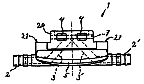
In Fig. la 1 indicates a main body having oppositely directed
outgoing coupling means 2 and 2', which over channels 3 and 3'
respectively are connected to first openings 8 and 8'
respectively which are placed in a plane extending in parallel
with the longitudinal direction of the main body, which is more
evident on Fig. lb and ic. In the areas around the first
openings 8, 8' portions of said plane comprises first sealing
surfaces 9 and 9' respectively. In Fig. lb further are shown
holding elements 6 on the main body 1 which are L-shaped,
longitudinal, inwardly directed rims which together with the
plane providing the sealing surfaces 9, 9' forms a linear guide
7 (Fig. lb) for co-operation with elements being intended to be
connected to the main body. 4 indicates coupling openings
allowing access to the guide 7 from the side in a way that will
be further explained below. When the main body according to the
invention is intended to be implanted, it is preferred that
means 5 for supporting growth of human tissue are arranged,
which means in this case are outwardly directed flange-like
wings, with possible holes penetrating the material. C.f. Fig.
6c, wherein in growth holes/sewing holes 45' are made in the
flange-like means 45.
From Fig. la it is further clear that the main body is made
with an overstructure 20 for connecting purposes with respect
CA 02306882 2000-04-19
WO 99/20338 PCT/SE98/01880
7
to a basic plane 21, which in turn is located below the plane
including the first sealing surfaces 9, 9'.
Fig. 2a shows a connecting member 10, which comprises conduits
11, 11' (indicated with interrupted lines) for the connection
with an external circuit over a nipple portion 13 for the
connection of tubing or the like. The connecting member 10 is
further provided with holding means 17 formed as sideways
directed linear flanges which are intended to co-operate with
the holding elements 6 of the main body (see particularly Fig.
1b). Further 14 indicates sideways directed snap wings for
locking co-operation with the openings 4 in the main body (see
Fig. la). 18 indicates locking shoulders which prevent a
connecting member 10 from being brought through the guide 7 of
the main body, and these shoulders are intended to co-operate
with shoulder recesses 19 in the main body (see Fig. ic) for
adequate positioning of the connecting member on the main body.
The corresponding is also true for other parts intended to be
connected to the main body, for example the protective member
(see Fig. 3a-b).
The holding means 17 provides in this case essentially
centrally located pressing portions 15 which are comprised of
somewhat vaulted resilient portions of the strips 17, said
pressing portions 15 being separated sideways from the main
part of the connecting member 10 through slots 16. In use these
portions 15 will guarantee safe pressing of the sealing
surfaces against each other while allowing adequate absorption
of possible play at the holding elements of the main body.
From Fig. 2b the drawing of one of the conduits 11 inside the
connecting member, from the second opening 12 with surrounding
second sealing surfaces to the nipple portion 13, is more
clearly shown.
CA 02306882 2000-04-19
WO 99/20338 PCT/SE98/01880
8
From Fig. 2c the construction of the holding means 17 is shown
in more detail and being designed as strip-like guide flanges,
and the locking shoulders 18 which through their co-operation
with the recesses 19 assure fastening and correspondence with
respect to the arrangement of openings. Interrupted lines
indicate the second openings 12, 12', and 22, 22' indicate the
respective second sealing surfaces.
Fig. 3a shows a protective member 24 with means 14, 15, 17
corresponding to the connecting member. It is further shown
that the protective member is essentially plate-like having a
transverse oblong recess 25, which in the applied position
comprises connection channel between the openings 8, 8' in the
main body in order to guarantee a continuos flow through the
main body. 26 indicates the sealing surface surrounding the
recess 25 (best shown in Fig. 3b) and which is co-operating
with corresponding sealing surfaces on the main body.
Fig. 4 shows a protective body 27, which also function as a
guiding body in respect of the connecting/disconnecting
procedures, whereby 28 indicates a linear guide which
corresponds to and is intended to coincide with the guide 7 of
a main body 1 being inserted into a recess 29 which is adapted
for that purpose and which thus is intended to receive the main
body 1 surrounding its upper structure 20 (see Fig. 1a),
whereby the material thickness of the protective body in the
area of the guide is adapted to correspond to the distance
between the base plane 21 of the main body 1 and the surface
including the sealing surfaces 9, 9'. The protective body -
guiding body 27 also includes a fastening arm 31, which is
pivoted onto the main part of the body at 32 and which is
provided with a snap lock means 33 for co-operation with a snap
protrusion 34 at the upper part of the main part. Sideways
CA 02306882 2000-04-19
WO 99/20338 PCT/SE98/01880
9
directed projections 30 are adapted, in the inserted position
of the main body 1 and the upwards pivoted position of the
fastening arm 31, to penetrate the openings 4 in the main body
1 and thereby on the one hand safely grip the main body, on the
other hand press the snap wings 14 belonging to a protective
member 24 being applied on the main body inwardly in such a way
that they will disengage from the respective opening 4. Hereby
protective member 24 is thus made free from the main body 1 and
may be removed. This is accomplished by the connecting member
10, which is placed in the guide 28 of the protective body 27
being brought in the direction upwards as seen in the figure,
whereby thus, at the same time the protective member 24 will
come out from the main body 1 and be brought upwardly into the
upper part of the guide 28. A continued insertion of the
connecting member will result in the shoulders 18 abutting the
shoulder recesses 19 while simultaneously the snap wings 14
will come in level with the openings which are most at the
bottom of the figure. Final snapping-in will be obtained at the
opening of the arm 31, when the projections 30 are removed from
the openings 4 whereby safe and adequate locking of the
connecting member 10 into the main body 1 is guaranteed. The
protective body may now be removed from the main body by the
arm 31 being pivoted downwardly and the protective body being
brought sideways away from the main body. Through the invention
is thus obtained very simple and fast switching from - as an
example in case of an implanted blood vessel valve having two
couplings - a position with active by-pass function through the
channel of the protective member to a position with connected
connecting member. In order to assure gathering of the
connecting member and the protective member in the displacement
direction, and thereby avoid separation in a longitudinal
direction of these parts in connection with switching and at
the same time simplify the displacement process, a displacement
slide is preferably arranged so as to be adapted displaceably
CA 02306882 2000-04-19
WO 99/20338 PCT/SE98/01880
on the guide of the protective body and comprising on the one
hand means for controlling the position of the elements in the
displacement direction, on the other hand for common
displacement effect in the form of a "thumb grip" or the like.
5 This arrangement guarantees limited strain to the integration
of the skin with the main body.
In order to connect an external circuit, a patient having an
implanted main body thus needs a connecting unit including a
10 connecting member applied on and being protected by a
protective body for the connecting procedure, and after
completed treatment he will need a protective unit consisting
of a new protective member applied to and being protected by a
new protective body. Both these units are advantageously single
use articles.
From Fig. 5 the design of the protective body is shown - the
guiding body 27 having upwardly pivoted and snapped-on
fastening arm 31. Freeing of the coupling member and by the way
of the membrane member from the main body is accomplished in
correspondence with what has been said above with respect to
the protective member. When a member, coupling member,
protective member or membrane member, is to be applied on the
main body, the movement of insertion is opposite to the
movement of the member to be replaced in the shown embodiment.
It is however not excluded that the same movement of insertion
be used. In that case the holding arrangement onto the main
body is modified.
On the modified main body 41 in Fig. 6a - c the outward
coupling means 42 and 42' are directed somewhat obliquely
downwards in order to enhance the flow through channels and
facilitate placement at implantation. In this case there are
only two diagonally located coupling openings 44 in order to
CA 02306882 2000-04-19
WO 99/20338 PCT/SE98/01880
11
assure safety against wrongful connection. 44' concerns a guide
opening shaped as an outwardly open one-way hole for co-
operation with a sideways directed holder projection in the
corresponding protective body/guiding body. 59 concerns in this
case only two diagonally located shoulder recesses. Also these
arrangements have the purpose of assuring adequate connection
of the different details.
The somewhat modified connecting member 50 in Fig. 7a and b is
provided with differently located nipple portions 53, which in
this case with their channels 51 are comprised of generally
straight continuations of channels 43 and 43' in the main body
(see Fig. 6a) which gives reduced flow resistance in the device
and thereby enhanced performance and also reduced tendency of
forming thrombus. Further, in the connecting member, there is
only one locking shoulder 58 and the snap wings 54 and the
pressing portions 55 are located diagonally. Altogether this
results in eliminating wrongful placement of the coupling
member onto the main body.
A further advantage with channel disposition according to the
invention is that it allows access to the channels in the main
body and to the bloodstream for "thrombectomy", i.e. removing
of coagulated blood or the like without surgery.
The invention may be modified within the scope of the following
claims and is not limited to the shown embodiments. The
invention may thus be used in a device with only one coupling
and then as an implant as well as a hose coupling for use
outside the human body.
Also other and differently shaped components may be arranged to
be connected to the main body, for example a membrane unit
which may have a construction essentially as the protective
CA 02306882 2000-04-19
WO 99/20338 PCT/SE98/01880
12
member 24 but having a penetrable membrane limiting the channel
25 from the surroundings. The membrane may in a per se known
manner be penetrated with a needle in order to allow blood
sampling or introduction of medicals etc. into the blood
stream.
The membrane unit 80 in Fig. 8a - c thus includes a main part
80' having a body 80' with a through hole into which a
penetratable membrane 81 is inserted sealingly. As the case
with the protective member in Fig. 3a - b having the recess 25,
here a connection channel 81 is provided which in this case is
formed of the material of the membrane, whereby a sealing
surface 82 is arranged surrounding the channel 81. This
arrangement results in that safe sealing effect may be obtained
between this surface 82 and the corresponding surface of the
main body, eliminating the need of surface treatment of the
surfaces. A membrane unit of this kind may also be allowed to
remain, at least during certain periods, on an implanted main
body and thus replace particular protective members (Fig. 3a -
b) so that there will be no need of switching between such.
parts before and after for example blood sampling or drug
administration.
As an alternative separate membrane units may be connected to a
connecting member over a hose (hoses).
Fig. 9 shows an assembly of the modified parts showing the
protective body 57 with a displacement slide 84 mounted on a
main body 41 and protective member and connecting member 50. 94
indicates a recess in the protective body forming a channel for
connection between the conduits 51 of the connecting member.
This construction allows prefilling of the channels in question
with a liquid such as a salt solution before application of the
connecting member in order to avoid introduction of air into
CA 02306882 2000-04-19
WO 99/20338 PCT/SE98/01880
13
the bloodstream resulting in further increased safety against
thrombus.
Fig. 10 a shows diagrammatically a protective body 57 with the
displacement slide 84 in an initial position, for example with
applied connecting member (not shown) to be applied to a main
body. The cover portion 85 is covering and prevents
manipulation with stopping and locking elements, namely a
locking tongue 86 which is placed in a first locking recess 87
in the protective body and first 89 and second 90 pawls,
whereof the first in this position co-operates with a first
catch recess 91. When connecting for example a connecting
member, the hand grip 93 is brought to the right in the figure,
whereby the first pawl is freed from its catch recess 91,
whereafter the entire slide may be brought to the right. In the
right position, in Fig. lOb, the locking tongue 86 co-operates
with a second locking recess 88, which is designed as a lock
catch for preventing movement to the left in the figure, and
the second pawl 90 co-operates with the second catch recess 92.
This way the protective body may not be reused unauthorised
whereby risks of infections by using potentially infected
material is avoided. Protective bodies constructed
correspondingly may be used for applying all the additional
parts.
The construction of details may deviate from shown embodiments.
The guide may thus be arranged differently, for example with
means corresponding to the holder elements 6 instead of being
placed on connecting member and vice versa. The guide may be
curved, for example circular, and the sealing surfaces may be
provided on a curved surface as seen perpendicular to the
connection direction. The drawing of channels may be arranged
differently with for example channels drawn in the same
direction in stead of in opposite directions.
CA 02306882 2000-04-19
WO 99/20338 PCT/SE98/01880
14
The placement of and provision of snap means such as snap
wings, locking shoulders etc. may deviate from what is shown.
Also the elements for freeing a snap-locked connecting member
or protective member may be varied with respect to construction
and location.
The device may be used as an implant or as a separate coupling
device having one or two outgoing couplings as well as openings
and conduits in the respective portion. The invention provides
several advantages whereof here only will be mentioned that the
construction provides a safe, painless and convenient access to
the bloodstream, so that it may be advantageously used by the
patient in the home instead of by trained personnel at a
hospital. This is also the result of using the spontaneous flow
as the propellant, i.e. the use of the heart as a pump for
propelling the blood through the blood treatment equipment or
the like is possible and facilitated by an equipment according
to the invention.
Materials which may be used are biocompatible if it is needed
for the application in question. The construction according to
the invention makes manufacture in synthetic materials well
adapted, possibly having surfaces treating with blood or/and
biocompatible coatings for all the parts in question. The parts
may then be comprised of single use articles which are possible
to produce at a low cost. Also manufacture in other material
such as titanium or titanium alloys, possible having surfaces
provided with blood and/or biocompatible layers for the
implantable main body, may come into question,