Note: Descriptions are shown in the official language in which they were submitted.
CA 02310190 2003-06-05
A PARALLEL PROCESSING DECIS1ON-FEEDBACK EQUALIZER
WITH L(:)OK-.AHEAD PROCESSING
Field of the Invention
The present invention relates generally to channel equalization techniques,
and
more particularly, to decision-feadback equalizers (DFEs) employing parallel
(block)
processing.
Background of the Invention
Signals arriving at: a receiver are typically corrupted by intersymbol
interference (ISI), cros~talk, echo, ~~nd other noise. 'thus, receivers must
jointly equalize the
channel, to compensate for such ir~tc,r5yrnbol interference and other
distortions, and decode
the encoded signals at increasingly hi<~h clock rates. Decision-feedback
equalization is a
widely-used technique: for removing intersymbol interference where noise
enhancement
caused by a linear feed-forward equalizer (F FE) may introduce performance
problems. For a
detailed discussion of decision feedback equalizers, see, for example, R.
Gitlin et al., Digital
Communication Principles. (Plenunu Press 199? ) and ):;..A. L,ee arid D.U.
Messerschmitt,
Digital Communications, (Kluwer ,Academic Press, 1988). Generally, decision-
feedback
equalization utilizes a nonlinear equalizer to equalize the channel using a
feedback loop based
on previously decided symbols. Since decision-feedback equalization techniques
are
nonlinear, the decision-feedback eclualizution process does not enhance the
channel noise.
In many high-speec;l <rppl:ications, such as Fast Ethernet 100BASE-TX, mass
storage, Gigabit Ethernet, or Sync lrronous Optical Networks (SONFT), the
symbol rates are
high. For example, the Fast Ethernet 1 UOBASE-TX stmdard uses a clock rate of
125MHz.
Thus, the equalization and decoding computations performed by the decision-
feedback
equalization must be performed at a clock period of 8 nanoseconds. Other
advanced data
networking applications, such as the SONET standard, may require even shorter
clock
periods. In many cakes, such a short clock period makes the implementation of
a decision-
feedback equalizer challenging or infeasible and forms the critical path in
their
implementation.
A number of metluods have been proposed or suggested for speeding up the
decision-feedback equalization processing. For example, K. Parhi, ''Pipelining
in Algorithm
with Quantizer Loops". IEEE Tr~xrr,s°aet'ions on <'ircuits anal
Systems, Vol. 38, No. 7, 745-54
CA 02310190 2003-06-05
(July 1991), proposes a look-ahead architecture. Generally. a look-ahead
decision-feedback
equalization implementation transfornus the original decision-feedback
equalization feedback
loop into a look-ahead structure (with duplicate decision-feedback
equalizations for each
possible value) and a simple loop with only a large selection multiplexor and
one memory
device. The look-ahead technique precomputes the symbol value for each
possible variation,
then utilizes the multiplexor to select the appropriate symbol when the actual
value is
determined. The complexity of the look-ahead implementation is M~', where M is
the size of
symbol alphabet, and L is the rrun nber of coefficient taps in the decision-
feedback
c;qualization. The speed of the look-ahead method is limited by a select-and-
latch operation
to in the transformed simple loop.
Block (parallel) proc~.ssing techniques have also been proposed for speeding
up adaptive filters for high-speed communication applications. For a
discussion of block
processing techniques, see, for example, G.A. C'lark et al., "Block
Implementation of
~~daptive Digital Filters", Trans. on A.SSP, Vol. ASSP-29, No. 3, (June 1981).
Generally,
block processing increases the througl-rput of the system by processing
several inputs (made
available through proper buffering) irr one clock cycle using duplicated
hardware. In return,
the clock speed can be set at a lower and more feasible speed. For example, if
ten inputs are
processed in the same clock cycle, the processing clock speed can be lowered
to ten percent
(10%) of the clock speed of the received signal, while maintaining the same
throughput.
2o While block processing techniques effectively reduce the required
processing
speed for general adaptive filter applications, block processing cannot easily
be directly used
with decision-feedback equalizers because of an output dependency in the
feedback loop of
decision-feedback equalizations. In irhe feedback loop of a decision-feedback
equalizer, each
output depends on previous output vah.res that may not be available Pram the
previous cycle.
As apparent from the above-described deficiencies with conventional decision-
feedback
equalizers, a need exists for a technique that reduces the output dependency
arid further
speeds up decision-feedback equalization processing. United States Patent No.
6,363,112,
filed December 7, 1998, entitled '"A. Parallel Processing Decision-Feedback
Equalizer,"
assigned to the assignee of the presemt invention (hereinafter referred to as
"the Azadet
System"), discloses a parallel implementation of a decision-feedback
equalization that speeds
u~p decision-feedback equalization processing. While the Azadet System employs
look-ahead
techniques in each of a ;plurality of l:7arallel blocks to achieve performance
gains, the output
CA 02310190 2003-06-05
~~ependencies in the disclosed parallel decision-feedback equalization
nonetheless produce a
~~elay on the order of N, where N is the number of blocks.
,Summary of the Invention
Generall:~, a method ar d apparatus arev disclosed for increasing the
effective
processing speed of a parallel decision-feedback equalizer by combining block
processing and
look-ahead techniques in the selection (multiplexing) stage. The parallel
decision-feedback
equalizer of the Azadet System receives a plurality of symbol blocks in
parallel using a
plurality of corresponding input branches and utilizes look-ahe<rd techniques
within ;~ given
block to precompute all possible output values for the given block. The
present invention
1o extends the Azadet System by acing look-ahead techniques in the selection
stage to
precompute the effect of previous lvlocks on each subsequent block, and to
thereby remove
the serial output dependency.
The present invention reduces the delay in the critical path for parallel
decision-feedback equalizations by employing block processing and look-ahead
techniques in
the selection (multiplexing) stage to select the actual output values from
among the generated
possible values. Acec>rding to one aspeca of the invention, the parallel
decision-feedback
equalization includes a multiplexor tree structure that selects an appropriate
output value for
each block and precomputes the effect c>f previous blocks on each subsequent
block. A
multiplexing delay algorithm on ihca order of logN is employed to resolve the
output
2o dependency and thus speeds up parailel block processing decision-feedback
equalizations.
According to another aspect of the invention, the disclosed decision-feedback
equalization architecture can be combined with pipelining to completely
eliminate the critical
path problem. The present invention permits a pipeline implementation of the
disclosed
multiplexor array circuit, because there are no dependencies from one row of
the multiplexor
array to another row- and the select signal, yU, is needed only at the bottom
row of
multiplexors. Pipeline latches can 'i7e added after any row of multiplexors in
the multiplexor
array circuit and each pipelined segment of the multiplexor array can be
processed
simultaneously. The number of pipeline segments that can be formed is between
2 and logN,
where N is the number of parallel bloc:k.s.
The disclosed multi plexor tree circuitry for the parallel decision-feedback
equalizer groups multaplexor blocks into groups of two, referred to as block
pairs, and
-3-
CA 02310190 2003-06-05
;provides at least one mirltiplexor fo~° e:ach block, i, to select an
output value, y;, from among
'the possible precomputed values. Ire. addition, block pairs are also
progressively grouped into
block groups, such that the first block l;roup has one block pair, the second
block group has
two block pairs, and so on. The output of each parallel block depends on the
possible
~precomputed values generated by the look-ahead processors for the block, as
well as the
;actual values that are ultimately selected for each previous block. In order
to reduce the delay
in obtaining each actual output value:,, the present invention assumes that
each block contains
each possible value, and carries the assumption through to all subsequent
blocks. Thus, the
number of multiplexors required to select from among the possible values grows
according to
1o ~V~logN, where N is the block number.
For example, the first bloc><: is not influenced by previous blocks and
requires
~~nly one multiplexor to select from among the possible precomputed values.
The output of
the second parallel block depends orr the possible prec:omputed values
generated by the look-
;~head processors for the: second block, as well as the actual values that are
ultimately selected
for the frst block. Thus, the second block includes a mult.iplexor for
processing each of the
;assumed possible values of the first block (selection signal), with each
multiplexor receiving
'the possible precomputed values generated. by i:he look-ahead processors for
the second block
;~s inputs. In addition, the second 171ock includes a final multiplexor for
selecting the final
output value, y2. The inputs to the final multiplexor for the second block are
also applied as
2o inputs to multiplexors in the second block: group (blocks three and four).
The second block
group is processed in a similar manner, and the inputs to the final
multiplexor for the fourth
block are also applied as inputs to multiplexors in the next block group
comprised of the third
and fourth block pair (blocks five thi~o~rgh eight).
A more complete undGrStanding of the present invention, as well as further
features and advantages of the present invention, will be obtained by
reference to the
following detailed description and drawings.
Brief Description of the Drawings
FIG. 1 illlustrates a ccvtnvenCional decision-feedback equalizer structure;
FIG. 2A illustrates two neighboring multiplexors ml and m2, where the output
of ml is connected to the select input of m2;
CA 02310190 2003-06-05
FIG. 2B illustrates tlae transformation of the multiplexor m2 of FIG. 2A in
~~ccordance with the present invention, such that all possible values are
precomputed and
applied to the multiplexor m2' for selection by the select signal of
multiplexor ml;
FIG. 3 illustrates a conventional bhxk processing implementation of a
decision-feedback equalizer, where the nunnber of parallel blocks is eight;
FIG. 4 illustrates a multiplexor tree array in accordance with the present
invention for the parallel decision-i~~:edbavk equalizer of FIG. 3 to produce
a delay on the
order of IogN; and
FIG. 5 illustrates an alternate implementation of the multiplexor tree array
of
1~1G. 4 in accordance with the press pt invention having a delay on the order
of logN and
reduced complexity.
Detailed Description
The present invention speeds up decision-feedback equalization processing by
combining block processing and look-Wead techniques in the selection stage to
produce a
delay on the order of lo~;N. A block processing decision-feedback equalization
with a block
factor of N takes N inputs and produ~;es N outputs in parallel. Since each
output computation
depends on previous decisions, the c~.~n~put;~tion oi~the N outputs forms a
dependency chain in
block processing decision-feedback ~qualitations and generally requires a
multiplexing delay
time of N-1 when block processing is done sequentially. ~hhe present invention
employs a
multiplexing delay algorithm on the order of logN to resolve the output
dependency and thus
speeds up parallel block processing d~c,isio:n-feedback equalizations.
The output of each parallel block depends on the possible precomputed values
~;enerated by the look-ahead process>ors for the block, as well as the actual
values that are
ultimately selected for each previous; block. In order to reduce the delay in
obtaining each
actual output value, the present invention assumes that each block contains
each possible
value, and carries the assumption through to all sub:>equent blocks. Thus, the
number of
rnultiplexors required in each block to >elect from among the pc.>ssible
values grows according
to N~IogN, where N is the block number. A novel rr~ultiplexor tree
architecture selects the
actual output vales with. a significantly reduced delay. As soon as the
possible values are
computed, the output is selected thra~.agh meultiplexing.
CA 02310190 2003-06-05
The disclosed decision-feedback equalizer architecture groups multiplexor
Mocks into groups of two, and lnrcrvides one or more multiplexors for each
possible
precomputed value to ultimately compute the output values, y, independently
and
concurrently. The decision-feedback equalization is comprised of a tree of
multiplexors, and a
transform operation, discussed belovs~, is applied to non-overlapping
neighboring multiplexor
pairs, in parallel. A transformed pair is treated as a single multiplexor with
multiple outputs
amd is again grouped into neighborin;~ pairs. 'f his transform :end group-in-
pairs operation can
then be repeated, and th~~ select sign<;~I~~ closest to the beginning of the
dependency chain will
double its direct control distance eaci~ tune. By properly grouping the
original N multiplexors
in a tree fashion and repeatedly usiy; the "'transform" operation, the entire
dependency chain
c;an be computed in D plus one steps. where D is the tree depth and is equal
to logN (because
the select signal propagates a distant:. of ?~"~N equal to N).
DECISIOr~-l~'EEDBACK EQI1AI,1ZE:RS
FIG. 1 illustrates a conventional decision-feedback equalization structure
100.
r.
i5 The decision-feedback equalization filter output is ~[n] _- ~ rce_k y[n -
k] , where L is the
=i
length of the filter and w_k is the ktlY tap weight. Thus, the output of the
dicer 110 can be
expressed as:
c
y[n] _ ~~ x[n] -+- ~ ~' ~ a'( ri __ k ~, ~ C I )
k-~
where the function, Q, i~; a nonlinear function employed by the dicer 110,
mapping signals to
symbol alphabets {a; } for 0 <_ i mL~' . l~qi.~ation 1 leads to a
straightforward implementation,
namely, at clock cycle ,n, when x{r,; is available and all previous yin-kJ,
for all k:>0 are
already computed and known, the eq~.iaCion can be evaluated during the given
clock period.
-6-
CA 02310190 2003-06-05
MULTIPI:.EX:OR TERMINOL,O(xY
Generally, a multiplexor function is represented as m(io,i,,...,iN_1;
so,s,,...s"_~),
where sk indicates the sf:lect signals of the multiplexor, ir; indicates tile
data inputs, and N=2".
If the unsigned binary number s". ~ s"_2. . . so represents a number j, then
the output of the
multiplexor function, m(io,i~,...,iN_,; s",sr,...s"_,), is i;. T'he two
neighboring multiplexors,
ml and m2, shown in FIG. 2A, ca» be represented as m1(i,}~ . i~r,...,ir~_,~;
sor,s,l,...s"-y) and
m2(ioZ , I~Z,...,1N_~2; soZ,si2,...s"_r2), w'llc,re s;'= s;~-,r, for o < i = n-
-2 and s"_, =ml().
FIG. 2A illustrates t~vo neighboring multiplexors ml and m2, where the output
of ml is connected to the select inp~.~t of m2. According to a feature of the
present invention,
1o the structure of m2 is transformed I~~y crea.ting multiple copies of m~,
with one copy for each
of the possible output values of ml . '1-'he correct output of m2 is then
selected using th-a select
signal of ml. As shom~n in FLG. 2B. the transform operation changes the
multiplexor function
Of m2 t0 m2'( m2(lo~., 1~Z,...,1N_[~: Sr , ..S"~~~, 1(~~), lTl~(10z , alb,
..,1N_r2; Sr2,...Sn_22, lp), ...,
m2(io2 , lp,...,1N_j2; Sp,...S"_2~, li,_~r 4; S,}r,Sp,...S"_p). ~I'hC
multlpleXOr m2' 1S COIISIStent Wlth
original functionality of the multilvrlexor m2. The transformation from m2 to
m2' can be
viewed as propagating the control/select signals of m l to m2 through one
multiplexar delay.
In addition, the transformation from 1~~ to m2' can also be viewed as doubling
the distance
under the direct control of the selec~l signals of ml. In this manner, all the
possible values are
precomputed and applied to the nvul.tiplexor m2' and the appropriate value is
selected (as
2o opposed to computed) using the sel~:~c~l signal of multiplexor ml .
As discussed further below in conjunction with FIG. 4, the transform operation
can be applied to non-overlapping neighboring multiplexor pairs in parallel. A
transformed
pair can then be treated as a singlc; rnulti.plexor with multiple outputs and
again be grouped
into neighboring pairs. This transfcyrrn and group-in-pairs operation can then
be repeated, and
the select signals closest to the beginning of the dependency chain will
double its direct
control distance each time. By proloerly grouping the original hl multiplexors
in a tree fashion
and repeatedly using the "transform" operation discussed above in conjunction
with FIGS. 2A
and 2B, the entire dependency chain can be computed in I) steps, where D is
the tree depth
and is equal to logN (because the ssle;ct siignal propagates a distance of
2~°~N = N).
3p FIG. 3 provides a conceptual representation for a block processing
implementation of a decision-feef:lback equalizer ~~0, such as the
implementation of the
Azadet System, where the number of parallel blocks 311-318 is eight. Thus, if
the clock rate
CA 02310190 2003-06-05
of the received signal is C, the processing clock rate of the decision-
feedback equalizer 300
can be C/8. The illustrative decision-feedback equalization 300 shown in FIG.
3 is an
implementation for k=1 tap, with M==2 pos Bible values (levels) for each
symbol or bit.
As shown in FIG. 3. each parallel block 311-318 of the decision-feedback
equalizer 300 includes a single tap decision-feedback equalizer, such as the
decision-feedback
f;qualizations 321-a, 3'21-b for the t3rst block 31 l, for precomputing each
of the possible
output values, y;. Thereafter, tl~e possible precomputed values are applied to
the
corresponding iN data inputs of a multiplexor 331-338 for each block 311-318.
In the
illustrative implementation, a two-level (binary) signaling scheme is
employed. Thus, as
i0 shown in FIG. 3, the two possible values from the look-ahead decision-
feedback equalizers at
each block, such as the decision-feedback equalizations 321-a, 321-b for the
first block 310,
corresponding to the two possible values (0/1) of y;, are applied to the
corresponding ifl and it
inputs of each multiplexor 311-318. ()ace the actual value, y;, of a given
block 311-318 is
determined, the actual value is applied to the select signal of the
multiplexor l + 1 (for the
next block), to select th~° appropriate; next symbol or bit for the
next block y;+,.
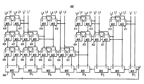
FIG. 4 illustrates a multiplexor array circuit 40() in accordance with the
present
invention that utilizes block prc~cessirrg and look-ahead techniques in the
selection
(multiplexing) stage to produce a clellay on the order of logN. The
illustrative multiplexor
array circuit 400 shown in FIG. 4 is an implementation for k---1 tap, with M=2
possible values
(levels) for each symbol or bit. fLn multiplexor array circuit 400 of FIG. 4
groups the
multiplexors 331-338 of FIG. 3 intc3 groups of two, and provides an array of
multiplexors, in a
manner described further below, lur selecting the appropriate precomputed
value for each
block pair independently and concurrently. 'thus, the i,r~ and irr inputs of
block 311 are
grouped with the io2 anal ir' inputs i~f block 312, as shown in FIG. 4.
Likewise, the io3 and ir3
inputs of block 313 are: grouped wirh the i~'r and i,'r inputs of block 314
(i~' and ir5 inputs are
grouped with io6 and l l 6 inputs, an~I i~;' and l, 7 inputs are grouped with
i~h and l, ~ inputs in a
similar manner).
As show in FIG. 4., the transform operation of the present invention is
applied
to non-overlapping neighboring multiplexor pairs, in parallel. A transformed
pair is treated as
a single multiplexor ~~ith multiple outputs and is again grouped into
neighboring pairs. This
transform and group-in-pairs operation can then be repeated. and the select
signals closest to
the beginning of the dependency chain, such as yo in FICA. 4, will double its
direct control
_g_
CA 02310190 2003-06-05
distance each time. B3~ properly grouping the original N multiplexors 311-318
in a tree
fashion and repeatedly using the "tnensfortn" operation discussed above in
conjunction with
FIGS. 2A and 2B, the entire depender~.cy chain can be computed in D steps,
where D is the
tree depth and is equal to logN (becamsc the select signal propagates a
distance of 2~°gN equal
to N).
The output of block 7~ 1 'l (FIG. 3) is determined by the two possible values
ion
<~.nd i, ~ and the select signal, y~°. 'I he output of oath subsequent
block 312-318 (FIG. 3) is
determined by the two possible input v°alues i~,~ and i,~' arid the
output of the previous block
:311-317. The present invention utilizes look-ahead techniques in the
selection stage to
to produce a delay on the order of logy .
In the ibllowing discussion of FIG. 4, it is assumed that all multiplexing
operations take an equal amount of time At a time, t, equal tc> 0, when all
id's and il's are
available it is not knovm whether i,~~ or i,~ will be chosen, fc~r k=1 through
8. The present
invention, however, utilizes the fact that: either i,,~ or i,~' will be. the
final correct value.
Initially, for each independent blocl~: pair, the correct value is assumed to
be i~~' (i,~, i~~, iis,
i~~), and the iIk value is applied to ~:he; corresponding multiplexors 41 l,
413, 415, 417 in the
first row of each block :pair, as shown in FICi. 4. The i,~ value selects i"2
or i~z for multiplexor
411, io4 or i~4 for multiplexor 413, i"~' or iic' for multiplexor 415, and i"8
or i~g for multiplexor
417.
2o In addition, for each independent block pair, the alternate correct value
(in the
two-level illustration) is also assumed to be ion (i~,~, i~', io', i~~), and
the ion' value is applied to
the corresponding multiplexors 412, 414, 416, 417 in the first row of each
block pair, as
shown in FIG. 4. The i«~' value selects io'' or i,2 for multiplexor 412, i~,'~
or i,'~ for multiplexor
414, io6 or i,6 for multi;plexor 416, a.nd i"8 or i,8 for multiplexor 418.
Therefore, at a time., t, edu.al to one multiplexor delay time, for each block
pair
(i) the output of the rnultiplexors ~l 11, 413, 41 S, 417 contain the correct
output valve if the
corresponding i~ 1 , il~, i,5, i,~ value is the correct value, or (ii) the
output of the multiplexors
412, 414, 416, 418 contain the correct output value if the corresponding i~~,
i~3, i«', ion value
is the correct value. 'The outputs ol~the multiplexors 411, 412 represent the
possible values of
output y2 of the block: 312 (FI('~. ~7). It is also noted that even though
which assumption is
correct remains unknown, the choice of which multiplexor for each block pair
in the first row
contains the correct value no longer depends on the output value of the
preceding block y1,
_9_
CA 02310190 2003-06-05
y3, y5, y7. The duplicated multiplexnng for each possihle precomputed value
provided by the
f~resent invention allows the choice c~y1' v44 uich multiplexor for each block
pair in the first row
containing the correct value to depend solely on y«. In other words, the
distance (selections)
Lender the direct control of y~ is doubl~.d from 1 to 2 blocks (for outputs y,
and y2).
Similarly., in processin g, the second row of multiplexors 421-428 in fIG. 4,
which of multiplexors 411 or 412 for the first block pair or multiplexors 415
or 416 for the
third block pair contains the final correct value remains unknown. Initially,
it is assumed that
rnultiplexors 411 and 415 contain thr~ correct value and the corresponding
value is applied to
rnultiplexors 421 and 423 in the second block pair and multiplexors 425 and
427 in the fourth
block pair. At the same time, it is assumed that multiplexors 412 and 416
contain the correct
value and the corresponding value is applied to multiplexors 422 and 424 in
the second block
pair and multiplexors 426 and 428 in tl~o fourth block pair.
Therefore, at a time, t. equal to two muitiplexor delay times, if the
multiplexor
~ll 1 contains the correct value (whic;h in turn means the t, ~ value is the
correct value), the
output of the multiplexor 411 selects the outputs of the multiplexors 421 and
423 as the y3
and y4 outputs. Likewise, if the m~.zltiplexor 412 contains the correct value
(which in turn
means the ion value is the correct val~mj, the output of the multiplexor 412
selects the outputs
of the multiplexors 422 and 424 as the y~ and y4 outputs. ~flne output of
multiplexor 421 and
422 represent the possible values of output y3 of the block 313 (FIG. 3). The
output of
multiplexor 423 and 421 represent tlue possible values of output y~ of the
block 314 (FIG. 3).
The choices for y1, y2, y3, y4 at this point are solely determined by y~. In
other words, the
distance under the direct control of ~,~o is doubled to 4 blocks. Similarly,
at a time, t, equal to
three multiplexor delay times, all eight output values are directly controlled
(selected) by yo,
with the selection being performed h~y the. last row of rnultiplexors.
FIG. 5 illustrates a z:lecision-feedback equalizer 500 in accordance with the
present invention having a delay ors the order of logN. The multiplexor array
circuit 500 of
FIG. 5 is a simplified version of the multiplexor array circuit 400 of FIG. 4.
The first
multiplexor 511 of the multiplexor array circuit 500 selects the correct value
for the first
stage. The simplified architecture is achieved by a utilizing a multiplexor
511 at t:he first
3o stage, controlled by the select signal y,~".
-to-
CA 02310190 2003-06-05
The comylexity of the multiplexor array circuit S00 (FIG. 5) is logN*N -N+2
multiplexors, compared with a comt7lexity of N*IogN +N for the rnultiplexor
array circuit
400 of FIG. 4. Savings ~tre more significant for smal l N.
The architecture of th;~ multiplexor array circuit 400 of FICi. 4 lends itself
to a
pipeline implementation, because they select signals, yo, are needed only at
the bottom row of
rnultiplexors 450. In addition to a traditional pipeline implementation of the
speculative
finite impulse response' (FIK) filti~rs, pipeline latches can be added after
any row of
rnultiplexors in the multiplexor arra,,~ circuit 400 of FIG. 4. Specifically,
since there are no
dependencies from one row of the tnultiple;xor array 4t~)0 to another row,
pipeline latches can
1o be added after any row of multiplexor;> in the multiple:xor array circuit
400 of FIG. 4. Thus.
f;ach segment of the multiplexor arraty 400 can be processed simultaneously.
The number of
pipeline segments that can be formed is between 2 and logN. In one
implementation, the
multiplexor array 400 is divided into two segments after the second row of
multiplexors,
utilizing pipelining techniques. WI»:n IogN segments are used, the
architecture has the most
relaxed critical path tuning constraint., with just a single multiplexor delay
plus one register
latch delay. It is noted that while the critical path seems to be equal to
that of a traditional
look-ahead implementation, such as those described in K. Parhi, ''Pipelining
in Algorithm
with Quantizer Loops". IEEF, Trana~cz~caio~Z,v on C'irc:uits and ~Svstems,
Vol. 38, No. 7, 745-54
(July 1991 ), the clock is operated at ,:r reduced frequency of f/N. 'The
decision-feedback
2o equalization architecture shown in F ICiS. 4 and 5 thus allows decision-
feedback equalizations
to operate at a very high speed. In theory, the architecture of the present
invention removes
the limit on how fast a decision-feedback t;qualization can operate.
It is to be understood that the embodiments and variations shown and
described herein are merely illustrGttive of the principles of this invention
and that various
modifications may be implemented by those skilled in the art without departing
from the
scope and spirit of the invention. F~5>r example, while the invention has been
illustrated with a
binary implementation using 2-level signals, the present invention can be
easily generalized to
mufti-level signals.