Note: Descriptions are shown in the official language in which they were submitted.
CA 02311487 2000-OS-25
n v y , .
WO 99/58050 PC'T/US99I10379
SIGNAL PROCESSING FOR MEASUREMENT
OF PHYSIOLOGICAL ANALYTES
Field of the Invention
The invention relates generally to methods for
continually or continuously measuring the concentration
of target chemical analytes present in a biological
system. More particularly, the invention relates to
methods for processing signals obtained during
measurement of physiological analytes. One important
application of the invention involves a method for
monitoring blood glucose concentrations.
Backctround of the Invention
A number of diagnostic tests are routinely
performed on humans to evaluate the amount or existence
of substances present in blood or other body fluids.
These diagnostic tests typically rely on physiological
fluid samples removed from a subject, either using a
syringe or by pricking the skin. One particular
diagnostic test entails self-monitoring of blood glucose
levels by diabetics.
Diabetes is a major health concern, and treatment
of the more severe form of the condition, Type I
(insulin-dependent) diabetes, requires one or more
insulin injections per day. Insulin controls
utilization of glucose or sugar in the blood and
prevents hyperglycemia which, if left uncorrected, can
lead to ketosis. On the other hand, improper
administration of insulin therapy can result in
1 I
CA 02311487 2000-OS-25
WO 99/58050 PCTIUS99I10379
hypoglycemic episodes, which can cause coma
and death. Hyperglycemia in diabetics has been
correlated with several long-term effects of diabetes,
such as heart disease, atherosclerosis, blindness,
stroke, hypertension and kidney failure.
The value of frequent monitoring of blood glucose
as a means to avoid or at least minimize the
complications of Type I diabetes is well established.
Patients with Type II (non-insulin-dependent) diabetes
can also benefit from blood glucose monitoring in the
control of their condition by way of diet and exercise.
Conventional blood glucose monitoring methods
generally require the drawing of a blood sample (e. g.,
by fingerprick) for each test, and a determination of
the glucose level using an instrument that reads glucose
concentrations by electrochemical or colorimetric
methods. Type I diabetics must obtain several
fingerprick blood glucose measurements each day in order
to maintain tight glycemic control. However, the pain
and inconvenience associated with this blood sampling,
along with the fear of hypoglycemia, has led to poor
patient compliance, despite strong evidence that tight
control dramatically reduces long-term diabetic
complications. In fact, these considerations can often
lead to an abatement of the monitoring process by the
diabetic. See, e.g., The Diabetes Control and
Complications Trial Research Group (1993) New Engl. J.
Med. 329:977-1036.
Recently, various methods for determining the
concentration of blood analytes without drawing blood
have been developed. For example, U.S. Patent No.
5,267,152 to Yang et al. describes a noninvasive
2
CA 02311487 2000-OS-25
WO 99/58050 PCT/US99110379
technique of measuring blood glucose concentration using
near-IR radiation diffuse-reflection laser spectroscopy.
Similar near-IR spectrometric devices are also described
in U.S. Patent No. 5,086,229 to Rosenthal et al. and
U.S. Patent No. 4,975,581 to Robinson et al.
U.S. Patent Nos. 5,139,023 to Stanley et al., and
5,443.080 to D'Angelo et al. describe transdermal blood
glucose monitoring devices that rely on a permeability
enhancer (e. g., a bile salt) to facilitate transdermal
movement of glucose along a concentration gradient
established between interstitial fluid and a receiving
medium. U.5. Patent No. 5,036,861 to Sembrowich
describes a passive glucose monitor that collects
perspiration through a skin patch, where a cholinergic
agent is used to stimulate perspiration secretion from
the eccrine sweat gland. Similar perspiration
collection devices are described in U.S. Patent No.
5,076,273 to Schoendorfer and U.S. Patent No. 5,140,985
to Schroeder.
In addition, U.S. Patent No. 5,279,543 to Glikfeld
et al. describes the use of iontophoresis to
noninvasively sample a substance through skin into a
receptacle on the skin surface. Glikfeld teaches that
this sampling procedure can be coupled with a glucose-
specific biosensor or glucose-specific electrodes in
order to monitor blood glucose. Finally, International
Publication No. WO 96/00110, published 4 January 1996,
describes an iontophoretic apparatus for transdermal
monitoring of a target substance, wherein an
iontophoretic electrode is used to move an analyte into
a collection reservoir and a biosensor is used to detect
the target analyte present in the reservoir.
3
CA 02311487 2000-OS-25
WO 99/58050 PCT/US99I10379
Summary of the Invention
The present invention provides a method for
continually ox continuously measuring the concentration
of an analyte present in a biological system. The
S method entails continually or continuously detecting an
analyte from the biological system and deriving a raw
signal therefrom, wherein the raw signal is related to
the analyte concentration. A number of signal
processing steps are then carried out in order to
convert the raw signal into an initial signal output
that is indicative of an analyte amount. The converted
signal is then further converted into a value indicative
of the concentration of analyte present in the
biological system.
The raw signal can be obtained using any suitable
sensing methodology including, for example, methods
which rely on direct contact of a sensing apparatus with
the biological system; methods which extract samples
from the biological system by invasive, minimally
invasive, and non-invasive sampling techniques, wherein
the sensing apparatus is contacted with the extracted
sample; methods which rely on indirect contact of a
sensing apparatus with the biological system; and the
like. In preferred embodiments of the invention,
methods are used to extract samples from the biological
sample using minimally invasive or non-invasive sampling
techniques. The sensing apparatus used with any of the
above-noted methods can employ any suitable sensing
element to provide the raw signal including, but not
limited to, physical, chemical, electrochemical,
photochemical, spectrophotometric, polarimetric,
colorimetric, radiometric, or like elements. In
4
CA 02311487 2003-11-19
preferred embodiments o~ tze invention, a biosensor is
used which comprises an electrochemical sensing element.
Ir. one particular embodiment of the invention, the
raw signal is obtained using a transdermal sampling
system that is placed in operative contact with a skir_
or mucosal surface o' the biological system. The
sampling system transdermally ex=racts the analyte =rom
the biological system using any appropriate sampling
technique, for example, iontophoresis. The transdermal
sampling system is maintained in operative contact with
the skin or mucosal surface of the biological system to
provide for such continual or continuous analyte
measurement.
The analyte can be any specific substance or
component that one is desirous of detecting and/or
measuring in a chemical, physical, enzymatic, or optical
analysis. Such analytes include, but are not limited
to, amino acids, enzyme substrates or products
indicating a disease state or condition, other markers
of disease states or conditions, drugs of abuse,
therapeutic and/or pharmacologic agents, electrolytes,
physiological analytes of interest (e. g., calcium,
potassium, sodium, chloride, bicarbonate (C02), glucose,
urea (blood urea nitrogen), lactate, hematocrit, and
hemoglobir_), lipids, and the like. In preferred
embodiments, the analyte is a physiological analyte of
interest, for example glucose, cr a chemical that has a
physiological action, for example a drug or
pharmacological agent.
Accordingly, it is an aspect of the invention to
provide a method for continually or continuously
measurir._g an analyte present in a biological system,
5
CA 02311487 2000-OS-25 ~,."._.
wo 99~ssoso
PCT/US99/10379
wherein raw signals are obtained from a suitable sensing
apparatus, and then subjected to signal processing
techniques. More particularly, the raw signals undergo
a data screening method in order to eliminate outlier
signals and/or poor (incorrect) signals using a
predefined set of selection criteria. In addition, or
alternatively, the raw signal can be converted in a
conversion step which (i) removes or corrects for
background information, (ii) integrates the raw signal
over a sensing time period, (iii) performs any process
which converts the raw signal from one signal type to
another, or (iv) performs any combination of steps (i),
(ii) and/or (iii). In preferred embodiments, the
conversion step entails a baseline background
subtraction method to remove background from the raw
signal and an integration step. In other embodiments,
the conversion step can be tailored for use with a
sensing device that provides both active and reference
(blank) signals; wherein mathematical transformations
are used to individually smooth active and reference
signals, and/or to subtract a weighted reference (blank)
signal from the active signal. In still further
embodiments, the conversion step includes correction
functions which account for changing conditions in the
biological system and/or the biosensor system (e. g.,
temperature fluctuations in the biological system,
temperature fluctuations in the sensor element, skin
conductivity fluctuations, or combinations thereof).
The result of the conversion step is an initial signal
output which provides a value which can be correlated
with.the concentration of -the target analyte in the
biological sample.
6
CA 02311487 2003-11-19
It is also an aspect of the invention to provide a
signal processing calibration step, wherein the raw or
initial signals obtained as described above are
converted into an ar_aiyte-specific value of known units
to provide an interpretation. of the signal obtained from
the sensing device. The interpretation uses a
mathematical transformation to model the relationship
between a measured response in the sensing device a..~.d a
corresponding analyte-specific value. Such mathematical
trar_sformations can entail the use of linear or
nonlinear regressions, or neural network algorithms. In
one embodiment, the calibration step entails calibrating
the sensing device using a single- or mufti-point
calibration, and then converting post-calibration data
using correlation factors, time corrections and
constants to obtain an analyte-specific value. Further
signal processing can be used to refine the information
obtained in the calibration step, for example, where a
signal processing step is used to correct for signal
differences due to variable conditions unique to the
sensor element used to obtain the raw signal. In one
embodiment, this further step is used to correct for
signal time-dependence, particularly signal decline. In
another embodiment, a constant offset term is obtained,
which offset is added to the signal to account for a
nor_-zero signal at an estimated zero analyte
concentration.
Further, the methods of the present invention
include enhancement of skin permeability by pricking the
skin w=th micro-needles. In addition, the sampling
system can be programed to begin execution of sampling
and sens'_ng at a deffined time (s) .
7
CA 02311487 2003-11-19
It is yet a further aspect of the invention to
provide a monitoring system for continually or
continucusly measuring an analyte present in a
byological system. The monitoring system comprises, in
operative combination: (a) a sampling mear_s for
continually or continuously extracting the analyte from
the biological system, (b) a sensing means in operative
contact with the ar~alyte extracted by the sampling
means, and (c) a microprocessor means in operative
communication with the sensing means. The sampling
means is adapted for extracting the analyte across a
skin or mucosal surface of a biological system. The
sensing means is used to obtain a raw signal from the
extracted analyte, wherein the raw signal is
specifically related to the analyte. The microprocessor
means is used to subject the raw signal to a conversion
step, thereby converting the same into an initial signal
output which is indicative of the amount of analyte
extracted by the sampling means, and then perform a
calibration step which correlates the initial signal
output with a measurement value indicative of the
concentration of analyte present in the biological
system at the time of extraction. In one embodiment,
the monitoring system uses iontophoresis to extract the
analyte from the biological system. In other
embodiments, the monitoring system is used to extract a
glucose aralyte from the biological system. Further,
the microprocessor can be programed to begin execution
of sampling and sensing at a defined time(s).
In accordance with another aspect of the present
invention, there is provided one or more
microprocessors, comprising programming to control: a
8
CA 02311487 2003-11-19
measurement cycle comprising operating a sampling device
for extracting a sample from a biological system, the
sample comprising an analyte, and operating a sensing
device for sensing the analyte in the extracted sample
to obtain a raw signal that is related to the analyte
amount or concentration in the biological system, the
sensing device comprising a sensor, subjecting the raw
signal to a conversion step in order to convert the raw
signal to an initial signal output which is indicative
of the amount of analyte extracted by the sampling
system; performing a calibration step which converts the
initial signal output to a measurement value indicative
of the concentration of analyte present in the
biological system at the time of extraction; and
repeating the measurement cycle at least once to obtain
a plurality of measurement values.
In accordance with another aspect of the present
invention, the sampling device comprises one or more
collection reservoirs.
In accordance with another aspect of the present
invention, the sampling device uses an iontoph oretic
current to extract the analyte from the biological
system.
In accordance with another aspect of the present
invention, at least: one collection reservoir contains an
enzyme that reacts with the extracted analyt~ to produce
an electrochemically detectable signal.
I:~ accordance with another aspect of tr:~ present
invention, the analyte is glucose and the enzyme is
glucose oxidase.
In accordance with another aspect of the present
invention, the one or more microprocessors are further
8a
CA 02311487 2003-11-19
programmed to control temperature sensing means and skin
conductance sensing means.
In accordance with another aspect of the present
invention, the one or more microprocessors are
programmed to begin execution of sampling and sensing at
a defined time.
In accordance with another aspect of the present
invention, the sampling device uses an iontophoretic
current to extract the analyte from the biological
system.
In accordance with another aspect of the present
invention, the raw signal is subjected to a data screen
which invalidates or corrects poor or incorrect signals
based on a detected parameter indicative of a poor or
incorrect signal.
In accordance with another aspect of the present
invention, the data screen comprises applying a set of
selection criteria to the raw signal, wherein each
selection criterium is based on a different detected
parameter indicative of a poor or incorrect signal.
In accordance with another aspect of the present
invention, the data screen comprises monitoring changes
in temperature over time during operation of the
sampling and sensing devices, and a maximum temperature
change over time (d(temp)/d(time)) value is used to
invalidate or correct signals obtained durir.~ a
measurement cycle du=ing which the maximum
d(temp)/d(time) value was exceeded.
In accordance with another aspect of the present
invention, the data screen comprises monitoring
perspiration. levels in the biological system at selected
time points, and a maximum perspiration leve_ threshold
8b
CA 02311487 2003-11-19
is used to invalidate or correct signals obtained during
a measurement cycle during which the maximum
perspiration level threshold was exceeded.
In accordance with ancther asNect of the present
invention, the raw signal data is subjected to a data
screen comprising monitoring iontophoretic voltage
during operation of the sampling and sensing devices,
and using a maximum iontophoretic voltage value to
invalidate or correct signals obtained during a
measurement cycle during which the maximum voltage value
was exceeded.
In accordance with another aspect of the present
invention, the conversion step comprises a baseline
background subtraction method to remove background noise
from the raw signal.
In accordance with another aspect of the present
invention, the baseline background subtraction method
comprises using a temperature-corrected baseline value.
In accordance with another aspect of the present
invention, the baseline background subtraction method
comprises using a skin conductivity-corrected baseline
value.
In accordance with another aspect of the present
invention, the sampling device further comprises a
second collection reservoir which does not contain the
enzyme, and operation of the sensing device further
comprises obtaining a blank signal from the second
collection reservoir, which blank signal is used.in the
conversion step as a blank correction value to remove
background information from the initial signal output.
In accordance with another aspect of the present
inventic~, the sampling device further comprises a
8c
CA 02311487 2003-11-19
second collection reservoir containing an enzyme that
reacts with the extracted analyte to produce an
electrochemically detectable signal, and operation of
the sensing device comprises obtaining signals from the
first and second collection reservoirs.
In accordance with another aspect of the present
invention, the conversion step comprises integrating the
raw signal over a sensing time period corresponding to
obtaining the raw signal.
In accordance with another aspect of the present
invention, the conversion step comprises using a
mathematical transformation to individually smooth raw
signals obtained from the first and second collection
reservoirs.
In accordance with another aspect of the present
invention, the conversion step comprises using a
mathematical transformation to individually smooth raw
signals obtained from the first and second collection
reservoirs.
In accordance with another aspect of the present
invention, the conversion step further comprises using a
mathematical transformation to smooth the di=ferences
between raw signals obtained from the first and second
collection reservoirs.
In accordance with another aspect of the present
invention, the calibration step comprises a jingle-point
calibration against a calibration reference value.
In accordance with another aspect of th= present
invention, the calibration step comprises the use of a
neural network algorithm that correlates the initial
signa'_ output with a measurement value indicative of the
concentration of analyte present in the biological
8d
CA 02311487 2003-11-19
system at the time of extraction.
In accordance with another aspect of the present
invention, the defined time precedes performing the
calibration step.
In accordance with another aspect of the present
invention, the calibration step comprises the use of a
linear correlation to correlate the initial signal
output with a measurement value indicative of the
concentration of analyte present in the biological
system at a time of extraction.
In accordance with another aspect of the present
invention, the calibration step comprises compensating
for time-dependent behavior between raw signal
measurements obtained in different measurement cycles.
In accordance with another aspect of the present
invention, the time-dependent behavior comprises signal
decline between the measurement cycles.
In accordance with another aspect of the present
invention, the conversion step comprises using a
temperature correction function to correct for changes
in the biological system and/or changes in the sensing
device.
In accordance with another aspect of the present
invention, the changes in the biological system comprise
a change in temperature.
In accordance with another aspect of the present
invention, the convE=rsion step comprises correcting for
temperature changes occurring between a measurement of a
background signal in the sensing device and a
measurement of a raw signal, and during the measurement
of the raw signal.
In accordance with another aspect of the present
8e
CA 02311487 2003-11-19
invention, correcting for temperature changes comprises
using an Arrhenius correction function.
In accordance with another aspect of the present
invention, the temperature correction comprises using an
integral average temperature correction function
obtained from a measurement cycle to correct for
temperature at subsequent time points.
In accordance with another aspect cf the present
invention, the conversion step comprises correcting for
temperature differences between multiple signals
obtained from the sensing device.
In accordance with another aspect of the present
invention, the sample comprises the analyte glucose.
In accordance with another aspect of the present
invention, there is provided a monitoring device for
measuring an analyt:e present in a biological system, the
device comprising, the one or more microprocessors, the
sampling device, and the sensing device.
Additional aspects, advantages and nov== features
of the invention will be set forth in part in the
description which follows, and in part will become
8f
CA 02311487 2000-OS-25
WO 99158050 PCT/US99/10379
apparent to those skilled in the art upon examination of
the following, or may be learned by practice of the
invention.
Brief Description of the Drawings
Figure 1A depicts a top plan view of an
iontophoretic collection reservoir and electrode
assembly for use in a transdermal sampling device
constructed according to the present invention.
Figure 1B depicts the side view of the
iontophoretic collection reservoir and electrode
assembly shown in Figure 1A.
Figure 2 is a pictorial representation of an
iontophoretic sampling device which includes the
iontophoretic,collection reservoir and electrode
assembly of Figures 1A and 1H.
Figure 3 is a representation of one embodiment of a
bimodal electrode design. The figure presents an
overhead and schematic view of the electrode assembly
33. In the figure, the bimodal electrode is shown at 30
and can be, for example, a Ag/AgCl iontophoretic/counter
electrode. The sensing or working electrode (made from,
for example, platinum) is shown at 31. The reference
electrode is shown at 32 and can be, for example, a
Ag/AgCl electrode. The components are mounted on a
suitable nonconductive substrate 34, for example,
plastic or ceramic. The conductive leads 37 leading to
the connection pad 35 are covered by a second
nonconductive piece 36 of similar or different material.
In this example of such an electrode the working
electrode area is approximately 1.35 cm~. The dashed
line in Figure 3 represents the plane of the cross-
sectional schematic view presented in Figure 4.
9
CA 02311487 2000-OS-25
WO 99/58050 PCT/US99/10379
Figure 4 is a representation of a cross-sectional
schematic view of the bimodal electrodes as they may be
used in conjunction with a reference electrode and a
hydrogel pad. In the figure, the components are as
follows: bimodal electrodes 40 and 41; sensing
electrodes 42 and 43; reference electrodes 44 and 45; a
substrate 46; and hydrogel pads 47 and 48.
Figure 5 is an exploded pictorial representation of
components from a preferred embodiment of the automatic
sampling system of the present invention.
Detailed Description of the Preferred Embodiments
Before describing the present invention in detail,
it is to be understood that this invention is not
limited to particular compositions or biological systems
as such may, of course, vary. It is also to be
understood that the terminology used herein is for the
purpose of describing particular embodiments only, and
is not intended to be limiting.
It must be noted that, as used in this
specification and the appended claims, the singular
forms "a", "an" and "the" include plural referents
unless the content clearly dictates otherwise. Thus,
for example, reference to "a time-dependent variable"
includes a mixture of two or more such variables,
reference to "an electrochemically active species"
includes two or more such species, reference to "an
analyte" includes mixtures of analytes, and the like.
Unless defined otherwise, all technical and
scientific terms used herein have the same meaning as
commonly understood by one of ordinary skill in the art
to which the invention pertains. Although any methods
CA 02311487 2000-OS-25
~~.... . .
WO 99/58050 PCTNS99/10379
and materials similar or equivalent to those described
herein can be used in the practice for testing of the
present invention, the preferred materials and methods
are described herein.
S In describing and claiming the present invention,
the following terminology will be used in accordance
with the definitions set out below.
Definitions
The terms "analyte" and "target analyte" are
used herein to denote any physiological analyte of
interest that is a specific substance or component that
is being detected and/or measured in a chemical,
physical, enzymatic, or optical analysis. A detectable
signal (e. g., a chemical signal or electrochemical
signal) can be obtained, either directly or indirectly,
from such an analyte or derivatives thereof.
Furthermore, the terms "analyte" and "substance" are
used interchangeably herein, and are intended to have
the same meaning, and thus encompass any substance of
interest. In preferred embodiments, the analyte is a
physiological analyte of interest, for example, glucose,
or a chemical that has a physiological action, for
example, a drug or pharmacological agent.
A "sampling device" or "sampling system" refers to
any device for obtaining a sample from a biological
system for the purpose of determining the concentration
of an analyte of interest. As used herein, the term
"sampling" means invasive, minimally invasive or non-
invasive extraction of a substance from the biological
system, generally across a membrane such as skin or
mucosa. The membrane can be natural or artificial, and
can be of plant or animal nature, such as natural or
11
CA 02311487 2000-OS-25
WO 99158050 PCT/US99/10379
artificial skin, blood vessel tissue, intestinal tissue,
and the like. Typically, the sampling means are in
operative contact with a "reservoir," or "collection
reservoir," wherein the sampling means is used for
extracting the analyte from the biological system into
the reservoir to obtain the analyte in the reservoir. A
"biological system" includes both living and
artificially maintained systems. Examples of minimally
invasive and noninvasive sampling techniques include
iontophoresis, sonophoresis, suction, electroporation,
thermal poration, passive diffusion, microfine
(miniature) lances or cannulas, subcutaneous implants or
insertions, and laser devices. Sonophoresis uses
ultrasound to increase the permeability of the skin
(see, e.g., Menon et al. (1994) Skin Pharmacology 7:130-
139). Suitable sonophoresis sampling systems are
described in International Publication No. WO 91/12772,
published 5 September 1991. Passive diffusion sampling
devices are described, for example, in International
Publication Nos.: WO 97/38126 (published 16 October
1997); WO 97/42888, WO 97/42886, WO 97/42885, and WO
97/42882 (all published 20 November 1997); and WO
97/43962 (published 27 November 1997). Laser devices
use a small laser beam to burn a hole through the upper
layer of the patient's skin (see, e.g., Jacgues et al.
(1978) J. Invest. Dermatology 88:88-93). Examples of
invasive sampling techniques include traditional needle
and syringe or vacuum sample tube devices.
The term "collection reservoir" is used to describe
any suitable containment means for containing a sample
extracted from a biological system. For example, the
collection reservoir can be a receptacle containing a
material which is sonically conductive (e. g., water with
12
CA 02311487 2000-OS-25
WO 99158050 PCTIUS99/10379
ions therein), or alternatively, it can be a material,
such as, a sponge-like material or hydrophilic polymer,
used to keep the water in place. Such collection
reservoirs can be in the form of a hydrogel (for
example, in the form of a disk or pad). Hydrogels are
typically referred to as "collection inserts." Other
suitable collection reservoirs include, but are not
limited to, tubes, vials, capillary collection devices,
cannulas, and miniaturized etched, ablated or molded
l0 flow paths.
A "housing" for the sampling system can further
include suitable electronics (e. g., microprocessor,
memory, display and other circuit components) and power
sources for operating the sampling system in an
automatic fashion.
A "monitoring system," as used herein, refers to a
system useful for continually or continuously measuring
a physiological analyte present in a biological system.
Such a system typically includes, but is not limited to,
sampling means, sensing means, and a microprocessor
means in operative communication with the sampling means
and the sensing means.
The term "artificial," as used herein, refers to an
aggregation of cells of monolayer thickness or greater
which are grown or cultured in vivo or in vitro, and
which function as a tissue of an organism but are not
actually derived, or excised, from a pre-existing source
or host.
The term "subject" encompasses any warm-blooded
animal, particularly including a member of the class
Mammalia such as, without limitation, humans and
nonhuman primates such as chimpanzees and other apes and
monkey species; farm animals such as cattle, sheep,
13
CA 02311487 2000-OS-25
WO 99158050 PCT/US99110379
pigs, goats and horses; domestic mammals such as dogs
and cats; laboratory animals including rodents such as
mice, rats and, guinea pigs, and the like. The term does
not denote a particular age or sex. Thus, adult and
newborn subjects, as well as fetuses, whether male or
female, are intended to be covered.
As used herein, the term "continual measurement"
intends a series of two or more measurements obtained
from a particular biological system, which measurements
are obtained using a single device maintained in
operative contact with the biological system over the
time period in which the series of measurements is
obtained. The term thus includes continuous
measurements.
The term "transdermal," as used herein, includes
both transdermal and transmucosal techniques, i.e.,
extraction of a target analyte across skin or mucosal
tissue. Aspects of the invention which are described
herein in the context of "transdermal," unless otherwise
specified, are meant to apply to both transdermal and
transmucosal techniques.
The term "transdermal extraction," or
"transdermally extracted" intends any noninvasive, or at
least minimally invasive sampling method, which entails
extracting and/or transporting an analyte from beneath a
tissue surface across skin or mucosal tissue. The term
thus includes extraction of an analyte using
iontophoresis (reverse iontophoresis?, electroosmosis,
sonophoresis, microdialysis, suction, and passive
diffusion. These methods can, of course, be coupled
with application of skin penetration enhancers or skin
permeability enhancing technique such as tape stripping
or pricking with micro-needles. The term "transdermally
extracted" also encompasses extraction techniques which
14
CA 02311487 2000-OS-25
WO 99158050 PCTNS99/10379
employ thermal poration, electroporation, microfine
lances, microfine canulas, subcutaneous implants or
insertions, and the like.
The term "iontophoresis" intends a method for
transporting substances across tissue by way of an
application of electrical energy to the tissue. In
conventional iox~tophoresis, a reservoir is provided at
the tissue surface to serve as a container of material
to be transported. Iontophoresis can be carried out
IO using standard methods known to those of skill in the
art, for example, by establishing an electrical
potential using a direct current (DC) between fixed
anode and cathode "iontophoretic electrodes,"
alternating a direct current between anode and cathode
iontophoretic electrodes, or using a more complex
waveform such as applying a current with alternating
polarity (AP) between iontophoretic electrodes (so that
each electrode is alternately an anode or a cathode).
The term "reverse iontophoresis" refers to the
movement of a substance from a biological fluid across a
membrane by way of an applied electric potential or
current. In reverse iontophoresis, a reservoir is
provided at the tissue surface to receive the extracted
material.
"Electroosmosis" refers to the movement of a
substance through a membrane by way of an electric
field-induced connective flow. The terms iontophoresis,
reverse iontophoresis, and electroosmosis, will be used
interchangeably herein to refer to movement of any
sonically charged or uncharged substance across a
membrane (e. g., an epithelial membrane) upon application
of an electric potential to the membrane through an
sonically conductive medium.
The term "sensing device," "sensing means," or
CA 02311487 2000-OS-25
WO 99/58050 PCT/US99/10379
"biosensor device" encompasses any device that can be
used to measure the concentration of an analyte, or
derivative thereof, of interest. Preferred sensing
devices for detecting blood analytes generally include
electrochemical devices and chemical devices. Examples
of electrochemical devices include the Clark electrode
system (see, e.g., Updike, et al., (1967} Nature
214:986-988), and other amperometric, coulometric, or
potentiometric electrochemical devices. Examples of
chemical devices include conventional enzyme-based
reactions as used in the Lifescan° glucose monitor
(Johnson and Johnson, New Brunswick, NJ) (see, e.g.,
U.S. Patent 4,935,346 to Phillips, et al.).
A "biosensor" or "biosensor device" includes, but
is not limited to, a "sensor element" which includes,
but is not limited to, a "biosensor electrode" or
"sensing electrode" or "working electrode" which refers
to the electrode that is monitored to determine the
amount of electrical signal at a point in time or over a
given time period, which signal is then correlated with
the concentration of a chemical compound. The sensing
electrode comprises a reactive surface which converts
the analyte, or a derivative thereof, to electrical
signal. The reactive surface can be comprised of any
electrically conductive material such as, but not
limited to, platinum-group metals (including, platinum,
palladium, rhodium, ruthenium, osmium, and iridium),
nickel, copper, silver, and carbon, as well as, oxides,
dioxides, combinations or alloys thereof. Some
catalytic materials, membranes, and fabrication
technologies~suitable for the construction of
amperometric biosensors were described by Newman, J.D.,
et al. (Analytical Chemistry 67 (24) , 4594-4599, 1995) .
The "sensor element" can include components in
16
CA 02311487 2000-OS-25
WO 99/58050 PCT/US99I10379
addition to a biosensor electrode, for example, it can
include a "reference electrode," and a "counter
electrode." .The term "reference electrode" is used
herein to mean an electrode that provides a reference
S potential, e.g.,,a potential can be established between
a reference electrode and a working electrode. The term
"counter electrode" is used herein to mean an electrode
in an electrochemical circuit which acts as a current
source or sink to complete the electrochemical circuit.
Although it is not essential that a counter electrode be
employed where a reference electrode is included in the
circuit and the electrode is capable of performing the
function of a counter electrode, it is preferred to have
separate counter and reference electrodes because the
reference potential provided by the reference electrode
is most stable when it is at equilibrium. If the
reference electrode is required to act further as a
counter electrode, the current flowing through the
reference electrode may disturb this equilibrium.
Consequently, separate electrodes functioning as counter
and reference electrodes are most preferred.
In one embodiment, the "counter electrode" of the
"sensor element" comprises a "bimodal electrode." The
term "bimodal electrode" as used herein typically refers
to an electrode which is capable of functioning non-
simultaneously as, for example, both the counter
electrode (of the "sensor elementN) and the
iontophoretic electrode (of the "sampling means").
The terms "reactive surface," and "reactive face"
are used interchangeably herein to mean the surface of
the sensing electrode that: (1) is in contact with the
surface of an electrolyte containing material (e. g. gel)
which contains an analyte or through which an analyte,
or a derivative thereof, flows from a source thereof;
17
I 1
CA 02311487 2000-OS-25
WO 99/58050 PCT/US99/t0379
(2) is comprised of a catalytic material (e. g., carbon,
platinum, palladium, rhodium, ruthenium, or nickel
and/or oxides, dioxides and combinations or alloys
thereof) or a material that provides sites for
electrochemical reaction; (3) converts a chemical signal
(e. g. hydrogen peroxide) into an electrical signal
(e.g., an electrical current); and (4) defines the
electrode surface area that, when composed of a reactive
material, is sufficient to drive the electrochemical
reaction at a rate sufficient to generate a detectable,
reproducibly measurable, electrical signal that is
correlatable with the amount of analyte present in the
electrolyte.
The term "collection reservoir" and "collection
insert" are used to describe any suitable containment
means for containing a sample extracted from a
biological system. The reservoir can include a material
which is sonically conductive (e. g., water with ions
therein), wherein another material such as a sponge-like
material or hydrophilic polymer is used to keep the
water in place. Such collection reservoirs can be in
the form of a hydrogel (for example, in the shape of a
disk or pad). Other suitable collection reservoirs
include, but are not limited to, tubes, vials, capillary
collection devices, cannulas, and miniaturized etched,
ablated or molded flow paths.
An "sonically conductive material" refers to any
material that provides ionic conductivity, and through
which electrochemically active species can diffuse. The
sonically conductive material can be, for example, a
solid, liquid, or semi-solid (e.g., in the form of a
gel) material that contains an electrolyte, which can be
composed primarily of water and ions (e. g., sodium
chloride), and generally comprises 50% or more water by
18
CA 02311487 2000-OS-25
WO 99/58050 PCT/US99I10379
weight. The material can be in the form of a gel, a
sponge or pad (e. g., soaked with an electrolytic
solution), or any~other material that can contain an
electrolyte and allow passage therethrough of
S electrochemically active species, especially the analyte
of interest.
The term "physiological effect" encompasses effects
produced in the subject that achieve the intended
purpose of a therapy. In preferred embodiments, a
physiological effect means that the symptoms of the
subject being treated are prevented or alleviated. For
example, a physiological effect would be one that
results in the prolongation of survival in a patient.
A "laminate" , as used herein, refers to structures
comprised of at least two bonded layers. The layers may
be bonded by welding or through the use of adhesives.
Examples of welding include, but are not limited to, the
following: ultrasonic welding, heat bonding, and
inductively coupled localized heating followed by
localized flow. Examples of common adhesives include,
but are not limited to, pressure sensitive adhesives,
thermoset adhesives, cyanocrylate adhesives, epoxies,
contact adhesives, and heat sensitive adhesives.
A "collection assembly", as used herein, refers to
structures comprised of several layers, where the
assembly includes at least one collection insert, for
example a hydrogel. An example of a collection assembly
of the present invention is a mask layer, collection
inserts, and a retaining layer where the layers are held
in appropriate, functional relationship to each other
but are not necessarily a laminate, i.e., the layers may
not be bonded together. The layers may, for example, be
held together by interlocking geometry or friction.
An "autosensor assembly", as used herein, refers to
19
CA 02311487 2000-OS-25
WO 99/58050 PCT/US99I10379
structures generally comprising a mask layer, collection
inserts, a retaining layer, an electrode assembly, and a
support tray., The autosensor assembly may also include
liners. The layers of the assembly are held in
appropriate, functional relationship to each other.
The mask and retaining layers are preferably
composed of materials that are substantially impermeable
to the analyte (chemical signal) to be detected (e. g.,
glucose); however, the material can be permeable to
l0 other substances. By "substantially impermeable" is
meant that the material reduces or eliminates chemical
signal transport (e.g., by diffusion). The material can
allow for a low level of chemical signal transport, with
the proviso that chemical signal that passes through the
material does not cause significant edge effects at the
sensing electrode.
"Substantially planar" as used herein, includes a
planar surface that contacts a slightly curved surface,
for example, a forearm or upper arm of a subject. A
"substantially planar" surface is, for example, a
surface having a shape to which skin can conform, i.e.,
contacting contact between the skin and the surface.
By the term "printed" as used herein is meant a
substantially uniform deposition of an electrode
formulation onto one surface of a substrate (i.e., the
base support). It will be appreciated by those skilled
in the art that a variety of techniques may be used to
effect substantially uniform deposition of a material
onto a substrate, e.g., Gravure-type printing, extrusion
coating, screen coating, spraying, painting, or the
like.
The term "enzyme" intends any compound or material
which catalyzes a reaction between molecules to produce
one or more reaction products. The term thus includes
CA 02311487 2000-OS-25
WO 99/58050 PCT/US99/10379
protein enzymes, or enzymatically active portions
(fragments? thereof, which proteins and/or protein
fragments maybe isolated from a natural source, or
recombinantly or synthetically produced. The term also
encompasses designed synthetic enzyme mimetics.
The term "time-dependent signal decline" refers to
a detectable decrease in measured signal over time when
no decrease or change in analyte concentration is
actually occurring. The decrease in signal over time
may be due to a number of different phenomena.
The term "signal-to-noise ratio" describes the
relationship between the actual signal intended to be
measured and the variation in signal in the absence of
the analyte. The terms "S/N" and "SNR" are also used to
refer to the signal-to-noise ratio. "Noise," as used
herein, refers to any undesirable signal which is
measured along with the intended signal.
General Methods
The present invention relates to use of a device
for transdermally extracting and measuring the
concentration of a target analyte present in a
biological system. In preferred embodiments, the
sensing device comprises a biosensor. In other
preferred embodiments, a sampling device is used to
extract small amounts of a target analyte from the
biological system, and then sense and/or quantify the
concentration of the target analyte. Measurement with
the biosensor and/or sampling with the sampling device
can be carried out in a continual or continuous manner.
Continual or continuous measurements allow for closer
monitoring of target analyte concentration fluctuations.
21
I 1
CA 02311487 2000-OS-25
WO 99/58050 PCT/US99/10379
The analyte can be any specific substance or
component that one is desirous of detecting and/or
measuring in a chemical, physical, enzymatic, or optical
analysis. Such analytes include, but are not limited
to, amino acids, enzyme substrates or products
indicating a disease state or condition, other markers
of disease states or conditions, drugs of abuse,
therapeutic and/or pharmacologic agents (e. g.,
theophylline, anti-HIV drugs, lithium, anti-epileptic
drugs, cyclosporin, chemotherapeutics), electrolytes,
physiological analytes of interest (e. g., urate/uric
acid, carbonate, calcium, potassium, sodium, chloride,
bicarbonate (COz), glucose, urea (blood urea nitrogen),
lactate/lactic acid, hydroxybutyrate, cholesterol,
triglycerides, creatine, creatinine, insulin,
hematocrit, and hemoglobin), blood gases (carbon
dioxide, oxygen, pH), lipids, heavy metals (e. g., lead,
copper), and the like., In preferred embodiments, the
analyte is a physiological analyte of interest, for
example glucose, or a chemical that has a physiological
action, for example a drug or pharmacological agent.
In order to facilitate detection of the analyte, an
enzyme can be disposed in the collection reservoir, or,
if several collection reservoirs are used, the enzyme
can be disposed in several or all of the reservoirs.
The selected enzyme is capable of catalyzing a reaction
with the extracted analyte (in this case glucose) to the
extent that a product of this reaction can be sensed,
e.g., can be detected electrochemically from the
generation of a current which current is detectable and
proportional to the concentration or amount of the
analyte which is reacted. A suitable enzyme is glucose
22
CA 02311487 2000-OS-25
WO 99/58050 PCT/US99/10379
oxidase which oxidizes glucose to gluconic acid and
hydrogen peroxide. The subsequent detection of hydrogen
peroxide on an appropriate biosensor electrode generates
two electrons per hydrogen peroxide molecule which
create a current which can be detected and related to
the amount of glucose entering the device. Glucose
oxidase (GOx) is readily available commercially and has
well known catalytic characteristics. However, other
enzymes can also be used, so long as they specifically
catalyze a reaction with an analyze or substance of
interest to generate a detectable product in proportion
to the amount of analyte so reacted.
In like manner, a number of other analyte-specific
enzyme systems can be used in the invention, which
enzyme systems operate on much the same general
techniques. For example, a biosensor electrode that
detects hydrogen peroxide can be used to detect ethanol
using an alcohol oxidase enzyme system, or similarly
uric acid with urate oxidase system, urea with~a urease
system, cholesterol with a cholesterol oxidase system,
and theophylline with a xanthine oxidase system.
In addition, the oxidase enzyme (used for hydrogen
peroxide-based detection) can be replaced with another
redox system, for example, the dehydrogenase-enzyme NAD-
NADH, which offers a separate route to detecting
additional analytes. Dehydrogenase-based sensors can
use working electrodes made of gold or carbon (via
mediated chemistry). Examples of analytes suitable for
this type of monitoring include, but are not limited to,
cholesterol, ethanol, hydroxybutyrate, phenylalanine,
triglycerides, and urea. Further, the enzyme can be
eliminated and detection can rely on direct
23
I l
CA 02311487 2000-OS-25
WO 99/58050 PCT/US99/10379
electrochemical or potentiometric detection of an
analyte. Such analytes include, without limitation,
heavy metals (e. g:, cobalt, iron, lead, nickel, zinc),
oxygen,_carbonate/carbon dioxide, chloride, fluoride,
lithium, pH, potassium, sodium, and urea. Also, the
sampling system described herein can be used for
therapeutic drug monitoring, for example, monitoring
anti-epileptic drugs (e. g., phenytion), chemotherapy
(e.g., adriamycin), hyperactivity (e.g., ritalin), and
anti-organ-rejection (e. g., cyclosporin).
The methods for measuring the concentration of a
target analyte can be generalized as follows. An
initial step (Step A) entails obtaining a raw signal
from a sensing device, which signal is related to a
target analyte present in the biological system. The
raw signal can be obtained using any suitable sensing
methodology including, for example, methods which rely
on direct contact of a sensing apparatus with the
biological system; methods which extract samples from
the biological system by invasive, minimally invasive,
and non-invasive sampling techniques, wherein the
sensing apparatus is contacted with the extracted
sample; methods which rely on indirect contact of a
sensing apparatus with the biological system; and the
like. In preferred embodiments of the invention,
methods are used to extract samples from the biological
sample using minimally invasive or non-invasive sampling
techniques. The sensing apparatus used with any of the
above-noted methods can employ any suitable sensing
element to provide the signal including, but not limited
to, physical, chemical, electrochemical, photochemical,
spectrophotometric, polarimetric, colorimetric,
24
CA 02311487 2000-OS-25
WO 99158050 PCT/US9911a379
radiometric, or like elements. In preferred embodiments
of the invention, a biosensor is used which comprises an
electrochemical sensing element.
After the raw signal has been obtained, the signal
can undergo a data screening method (Step B) in order to
eliminate outlier signals and/or poor (incorrect)
signals using a predefined set of selection criteria.
In addition, or alternatively, the raw signal can be
converted in a conversion step (Step C) which can (i)
remove or correct for background information, (ii)
integrate the signal over a sensing time period, (iii)
perform any process which converts the signal from one
signal type to another, or (iv) perform any combination
of steps (i) , (ii) and/or (iii) . In preferred
embodiments, the conversion step entails a baseline
background subtraction method to remove background from
the raw signal and an integration step. In other
embodiments, the conversion step can be tailored for use
with a sensing device that provides both active and
reference (blank) signals; wherein mathematical
transformations are used to individually smooth active
and reference signals, and/or to subtract a weighted
reference (blank) signal from the active signal. In
still further embodiments, the conversion step includes
correction functions which account for changing
conditions in the biological system and/or the biosensor
system (e. g., temperature fluctuations in the biological
system, temperature fluctuations in the sensor element,
skin conductivity fluctuations, or combinations
thereof). The result of the conversion step is an
initial signal output which provides a value which can
be correlated with the concentration of the target
I
CA 02311487 2000-OS-25
WO 99!58050 PCTIUS99110379
analyte in the biological sample.
In a calibration step (Step D), the raw signal
obtained from~Step A, or the initial signal obtained
from Step B and/or Step C, is converted into an analyte-
specific value of known units to provide an
interpretation of the signal obtained from the sensing
device. The interpretation uses a one-to-one
mathematical transformation to model the relationship
between a measured response in the sensing device and a
corresponding analyte-specific value. Thus, the
calibration step is used herein to relate, for example,
an electrochemical signal (detected by a biosensor) with
the concentration of a target analyte in a biological
system. In one embodiment,. the calibration step entails
calibrating the sensing device using a single- or multi-
point calibration, and then converting post-calibration
data using correlation factors, time corrections and
constants to obtain an analyte-specific value. Further
signal processing can be used to refine the information
obtained in the calibration step, for example, where a
signal processing step is used to correct for signal
differences due to variable conditions unique to the
sensor element used to obtain the raw signal. In one
embodiment, this further step is used to correct for
signal time-dependence, particularly signal decline. In
another embodiment, a constant offset term is obtained,
which offset is added to the signal to account for a
non-zero signal at an estimated zero analyte
concentration.
The analyte value obtained using the above
techniques can optionally be used in a subsequent step
(Step E) to predict future (time forecasting) or past
26
CA 02311487 2000-OS-25
WO 99158050 PCTI1JS99/10379
(calibration) measurements of the target analyte
concentration in the biological system. For example, a
series of analyte values are obtained by performing any
combination of Steps A, B, C, and/or D in an iterative
manner. This measurement series is then used to predict
unmeasured analyte values at different points in time,
future or past. In this manner, lag times inherent in
certain sampling and/or sensing techniques can be
reduced or eliminated to provide real time measurement
predictions.
In another optional step, analyte values obtained
using the above techniques can be used in a subsequent
step (Step F) to control an aspect of the biological
system. In one embodiment, the analyte value obtained
in Step D is used to determine when, and at what level,
a constituent should be added to the biological system
in order to control an aspect of the biological system.
In a preferred embodiment, the analyte value can be used
in a feedback control loop to control a physiological
effect in the biological system.
The above general methods (Steps A through F) are
each independently useful in anaiyte sensing systems and
can, of course, be used in a wide variety of
combinations selected for a particular biological
system, target analyte, and/or sensing technique. For
example, in certain applications, a measurement sequence
can include Steps A, C, D, E and F, in other
applications, a measurement sequence can include Steps
A, 8, C and D, and the like. The determination of
particularly suitable combinations is within the skill
of the ordinarily skilled artisan when directed by the
instant disclosure. Furthermore, Steps C through F are
27
CA 02311487 2000-OS-25
WO 99/58050 PCTNS99110379
preferably embodied as one or more mathematical
functions as described herein below. These functions
can thus be carried out using a microprocessor in a
monitoring system. Although these methods are broadly
applicable to measuring any chemical analyte.and/or
substance in a biological system, the invention is
expressly exemplified for use in a non-invasive,
transdermal sampling system which uses an
electrochemical biosensor to quantify or qualify glucose
or a glucose metabolite.
Step A: Obtaining the raw signal.
The raw signal can be obtained using any sensing
device that is operatively contacted with the biological
system. Such sensing devices can employ physical,
chemical, electrochemical, spectrophotometric,
polarimetric, colorimetric, radiometric, or like
measurement techniques. In addition, the sensing device
can be in direct or indirect contact with the biological
system, or used with a sampling device which extracts
samples from the biological system using invasive,
minimally invasive or non-invasive sampling techniques.
In preferred embodiments, a minimally invasive or non-
' invasive sampling device is used to obtain samples from
the biological system, and the sensing device comprises
a biosensor with an electrochemical sensing element. In
particularly preferred embodiments, a sampling device is
used to obtain continual transdermal or transmucosal
samples from a biological system, and the analyte of
interest is glucose.
More specifically, a non-invasive glucose
monitoring device is used to measure changes in glucose
28
CA 02311487 2000-OS-25
WO 99/58050 PCT/US99/10379
levels in an animal subject over a wide range of glucose
concentrations. The sampling method is based on
transdermal glucose extraction and the sensing method is
based on electrochemical detection technology. The
device can be contacted with the biological system
continuously, and automatically obtains glucose samples
in order to measure glucose concentration at
preprogrammed intervals.
Sampling is carried out continually by non-
invasively extracting glucose through the skin of the
patient. More particularly, an iontophoretic current is
applied to a surface of the skin of a subject. When the
current is applied, ions or charged molecules pull along
other uncharged molecules or particles such as glucose
which are drawn into a collection reservoir placed on
the surface of the skin. The collection reservoir may
comprise any sonically conductive material and is
preferably in the form~of a hydrogel which is comprised
of a hydrophilic material, water and an electrolyte.
The collection reservoir may further contain an
enzyme which catalyzes a reaction of glucose to form an
easily detectable species. The enzyme is preferably
glucose oxidase (GOx) which catalyzes the reaction
. between glucose and oxygen and results in the production
of hydrogen peroxide. The hydrogen peroxide reacts at a
catalytic surface of a biosensor electrode, resulting in
the generation of electrons which create a detectable
biosensor current (raw signal). Based on the amount of
biosensor current created over a given period of time, a
measurement is taken, which measurement is related to
the amount of glucose drawn into the collection
reservoir over a given period of time. In a preferred
29
I I
CA 02311487 2000-OS-25
WO 99/58050 PC'T/US99/10379
embodiment, the reaction is allowed to continue until
substantially all of the glucose in the collection
reservoir has been subjected to a reaction and is
therefore no longer detectable, and the biosensor
current generated is related to the concentration of
glucose in the subject at the approximate time of sample
collection.
When the reaction is complete, the process is
repeated and a subsequent measurement is obtained. Mare
specifically, the iontophoretic current is again
applied, glucose is drawn through the skin surface into
the collection reservoir, and the reaction is catalyzed
in order to create a biosensor current. These sampling
(extraction) and sensing operations are integrated such
that glucose is extracted into the hydrogel collection
pad where it contacts the GOx enzyme. The GOx enzyme
converts glucose and oxygen in the hydrogel to hydrogen
peroxide which diffuses to the sensor and is catalyzed
by the sensor to regenerate oxygen and form electrons.
The electrons generate an electrical signal that can be
measured, analyzed, and correlated to blood glucose.
Optionally, one or more additional "active"
collection reservoirs (each containing the GOx enzyme)
can be used to obtain measurements. In one embodiment,
two active collection reservoirs are used, and an
average is taken between signals from the reservoirs for
each measurement time point. Obtaining multiple
signals, and then averaging reads from each signals,
allows for signal smoothing of unusual data points from
a sensor that otherwise may not have been detected by
data screening techniques. Furthermore, skin site
variability can be detected, and "lag" and/or "lead"
CA 02311487 2000-OS-25
WO 99158050 PCTIUS99/i0379
differences in blood glucose changes relative to
extracted glucose changes can be mitigated. In another
embodiment, a second collection reservoir can be
provided which does not contain the GOx enzyme. This
second reservoir can serve as an internal reference
(blank) for the sensing device, where a biosensor is
used to measure the "blank" signal from the reference
reservoir which signal is then used in a blank
subtraction step as described below.
A generalized method for continual monitoring of a
physiological analyte is disclosed in International
Publication No. WO 97/24059, published 10 July 1997. As
noted in that publication, the analyte is extracted into
a reservoir containing a hydrogel which is preferably
comprised of a hydrophilic material of the type
described in International Publication No. WO 97/02811,
published 30 January 1997. Suitable hydrogel materials
include polyethylene oxide, polyacrylic acid,
polyvinylalcohol and related hydrophilic polymeric
materials combined with water to form an aqueous gel.
In the above non-invasive glucose monitoring
device, a biosensor electrode is positioned on a surface
of the hydrogel opposite the surface contacting the
skin. The sensor electrode acts as a detector which
detects current generated by hydrogen peroxide in the
redox reaction, or more specifically detects current
which is generated by the electrons generated by the
redox reaction catalyzed by the platinum surface of the
electrode. The details of such electrode assemblies and
devices for iontophoretic extraction of glucose are
disclosed in International Publication No. WO 96/00110,
published 4 January 1996, and International Publication
31
I 1
CA 02311487 2000-OS-25
WO 99158050 PCT'/US99/10379
No. WO 97/10499, published 2 March 1997.
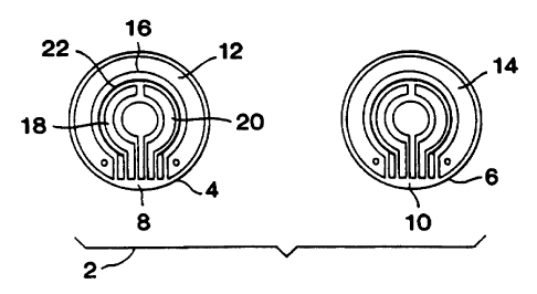
Referring now to Figures 1A and 1B, an
iontophoretic collection reservoir and electrode
assembly for use in a transdermal sensing device is
S generally indicated at 2. The assembly comprises two
iontophoretic collection reservoirs, 4 and 6, each
having a conductive medium 8, and 10 (preferably
cylindrical hydrogel pads), respectively disposed
therein. First (12) and second (14) ring-shaped
iontophoretic electrodes are respectively contacted with
conductive medium 8 and 10. The first iontophoretic
electrode 12 surrounds three biosensor electrodes which
are also contacted with the conductive medium 8, a
working electrode 16, a reference electrode 18, and a
counter electrode 20. A guard ring 22 separates the
bioser~sor electrodes from the iontophoretic electrode I2
to minimize noise from the iontophoretic circuit.
Conductive contacts provide communication between the
electrodes and an associated power source and control
means as described in detail below. A similar biosensor
electrode arrangement can be contacted with the
conductive medium 10, or the medium can not have a
sensor means contacted therewith.
Referring now to Figure 2, an exploded view of the
key components from a preferred embodiment of an
iontophoretic sampling system is presented. In Figure
2, the iontophoretic collection reservoir and electrode
assembly 2 of Figures IA and 1B is shown in exploded
view in combination with a suitable iontophoretic
sampling device housing 32. The housing can be a
plastic case or other suitable structure which
preferably is configured to be worn on a subjects arm in
32
CA 02311487 2000-OS-25
WO 99158050 PCTIUS99I10379
a manner similar to a wrist watch. As can be seen,
conductive media 8 and 10 (hydrogel pads) are separable
from the assembly 2; however, when the assembly 2 and
the housing 32 are assembled to provide an operational
iontophoretic sampling device 30, the media are in
contact with the electrodes to provide a electrical
contact therewith.
In one embodiment, the electrode assemblies can
include bimodal electrodes as shown in Figure 3.
1O Referring now to Figure 5, an exploded view of the
key components from one embodiment of an iontophoretic
sampling system (e. g., one embodiment of an autosensor
assembly) is presented. The sampling system components
include two biosensor/iontophoretic electrode
assemblies, 504 and 506, each of which have an annular
iontophoretic electrode, respectively indicated at 508
and 510, which encircles a biosensor 512 and 514. The
electrode assemblies 504 and 506 are printed onto a
polymeric substrate 516 which is maintained within a
sensor tray 518. A collection reservoir assembly 520 is
arranged over the electrode assemblies, wherein the
collection reservoir assembly comprises two hydrogel
inserts 522 and 524 retained by a gel retaining layer
526 and a mask layer 528.
In one embodiment, the electrode assemblies can
include bimodal electrodes as shown in Figure 3.
Modifications and additions to the embodiment of Figure
5 will be apparent to those skilled in the art in light
of the teachings of the present specification.
The components described herein are intended for
use in a automatic sampling device which is configured
to be worn like an ordinary wristwatch. As described in
International Publication No. WO 96/00110, published 4
33
I I
CA 02311487 2000-OS-25
WO 99/58050 PCT/US99/10379
January 1996, the wristwatch housing (not shown)
contains conductive leads which communicate with the
iontophoretic electrodes and the biosensor electrodes to
control cycling and provide power to the iontophoretic
electrodes, and to detect electrochemical signals
produced at the biosensor electrode surfaces. The
wristwatch housing can further include suitable
electronics (e.g., microprocessor, memory, display and
other circuit components) and power sources for
operating the automatic sampling system.
Modifications and additions to the embodiment of
Figure 2 will be apparent to those skilled in the art in
light of the teachings of the present specification.
A power source (e.g., one or more rechargeable or
nonrechargeable batteries) can be disposed within the
housing 32 or within the straps 34 which hold the device
in contact with a skin or mucosal surface of a subject.
In use, an electric potential (either direct current or
a more complex waveform) is applied between the two
iontophoretic electrodes 12 and 14 such that current
flows from the first iontophoretic electrode 12, through
the first conductive medium 8 into the skin or mucosal
surface, and then back out through the second conductive
medium 10 to the second iontophoretic electrode 14. The
current flow is sufficient to extract substances
including an analyte of interest through the skin into
one or both of collection reservoirs 4 and 6. The
electric potential may be applied using any suitable
technique, for example, the applied current density may
be in the range of about 0.01 to 0.5 mA/cmz. In a
preferred embodiment, the device is used for continual
or continuous monitoring, and the polarity of
iontophoretic electrodes 12 and 14 is alternated at a
34
CA 02311487 2000-OS-25
WO 99158050 PCT/US99/10379
rate of about one switch every ZO seconds to about one
switch every hour so that each electrode is alternately
a cathode or an anode. The housing 32 can further
include an optional temperature sensing element (e.g., a
thermistor, thermometer, or thermocouple device) which
monitors the temperature at the collection reservoirs to
enable temperature correction of sensor signals as
described in detail below. The housing can also include
an optional conductance sensing element (e.g., an
integrated pair of electrodes) which monitors
conductance at the skin or mucosal surface to enable
data screening correction or invalidation of sensor
signals as also described in detail below.
After a suitable iontophoretic extraction period,
one or both of the sensor electrode sets can be
activated in order to detect extracted substances
including the analyte of interest. Operation of the
iontophoretic sampling device 30 is controlled by a
controller 36 (e. g., a microprocessor), which interfaces
with the iontophoretic electrodes, the sensor
electrodes, the power supply, the optional temperature
and/or conductance sensing elements, a display and other
electronics. For example, the controller 3fi can include
a programmable a controlled circuit source/sink drive
for driving the iontophoretic electrodes. Power and
reference voltage are provided to the sensor electrodes,
and signal amplifiers can be used to process the signal
from the working electrode or electrodes. In general,
the controller discontinues the iontophoretic current
drive during sensing periods. A sensor confidence loop
can be provided for continually monitoring the sampling
system to insure proper operations.
I l
CA 02311487 2000-OS-25
WO 99J58050 PCTNS99I10379
In a further aspect, the sampling device can
operate in an alternating polarity mode using first and
second bimodal,electrodes (Figure 4, 40 and 41) and two
collection reservoirs (Figure 4, 47 and 48). Each bi-
modal electrode (Figure 3, 30; Figure 4, 40 and 41)
serves two functions depending on the phase of the
operation: (1) an electro-osmotic electrode (or
iontophoretic electrode) used to electrically draw
analyte from a source into a collection reservoir
comprising water and an electrolyte, and to the area of
the electrode subassembly; and (2) as a counter
electrode to the first sensing electrode at which the
chemical compound is catalytically converted at the face
of the sensing electrode to produce an electrical
signal.
The reference (Figure 4, 44 and 45; Figure 3, 32)
and sensing electrodes (Figure 4, 42 and 43; Figure 3,
31), as well as, the bimodal electrode (Figure 4, 40 and
41; Figure 3, 30) are connected to a standard
potentiostat circuit during sensing. In general,
practical limitations of the system require that the
bimodal electrode will not act as both a counter and
iontophoretic electrode simultaneously.
The general operation of an iontophoretic sampling
system is the cyclical repetition of two phases: (1) a
reverse-iontophoretic phase, followed by a (2) sensing
phase. During the reverse iontophoretic phase, the
first bimodal electrode (Figure 4, 40) acts as an
iontophoretic cathode and the second bimodal electrode
(Figure 4, 41) acts as an iontophoretic anode to
complete the circuit. Analyte is collected in the
reservoirs, for example, a hydrogel (Figure 4, 47 and
48). At the end of the reverse iontophoretic phase, the
36
CA 02311487 2000-OS-25
WO 99158050 PCTlUS99110379
iontophoretic current is turned off. During the sensing
phase, in the case of glucose, a potential is applied
between the reference electrode (Figure 4, 44) and the
sensing electrode (Figure 4, 42). The chemical signal
reacts catalytically on the catalytic face of the first
sensing electrode (Figure 4, 42) producing an electrical
current, while the first bi-modal electrode (Figure 4,
40) acts as a counter electrode to complete the
electrical circuit.
The electrode described is particularly adapted for
use in conjunction with a hydrogel collection reservoir
system for monitoring glucose levels in a subject
through the reaction of collected glucose with the
enzyme glucose oxidase present in the hydrogel matrix.
The bi-modal electrode is preferably comprised of
Ag/AgCl. The electrochemical reaction which occurs at
the surface of this electrode serves as a facile source
or sink for electrical current. This property is
especially important for the iontophoresis function of
the electrode. Lacking this reaction, the iontophoresis
current could cause the hydrolysis of water to occur at
the iontophoresis electrodes causing pH changes and
possible gas bubble formation. The pH changes to acidic
or basic pH could cause skin irritation or burns. The
ability of an Ag/AgCl electrode to easily act as a
source of sink current is also an advantage for its
counter electrode function. For a three electrode
electrochemical cell to function properly, the current
generation capacity of the counter electrode should not
limit the speed of the reaction at the sensing
electrode. In the case of a large sensing electrode,
the counter electrode should be able to source
proportionately larger currents.
The design of the sampling system provides for a
37
CA 02311487 2003-06-30
larger sensing electrode (see for example, Figure 3)
than previously designed. Consequently, the size of the
bimodal electrode should be sufficient so that who.~.
acting as a counter electrode with respect to the
S sensing electrode the counter electrode does r_o~ become
limiting the rate of catalytic reaction at the sensing
electrode catalytic surface.
Two met:~ods exist to ensure that the counter
electrode does not 1_m=t the current at the sensing
to electrode: (1) the bi-modal electrode is made much
larger than the sensing electrode, or (2) a facile
counter reaction is provided.
During the rove=se iontophoretic phase, the power
source provides a current flow to the first bi-modal
15 electrode to facilitate the extraction of the chemical
substance into the reservoir. During the sensing phase,
the power source is used to provide voltage to the first
sensing electrode to drive the conversion of chemical
signal retained in reservoir to electrical signal at the
20 catalytic face of the sensing electrode. The power
source also maintains a fixed potential at the electrode
where, for example hydrogen peroxide is converted to
molecular oxygen, hydrogen ions, and electrons, wh_ch is
compared with the potential of the reference electrode~
.25 during the sensing phase. While one sensing electrode
is operating in the sensing mode it is electrically
corrected to the adjacent bimodal electrode which acts
as a cour_ter electrode at which electrons generated at
the sensing electrode are consumed.
30 The electrode sub-assembly can be operated by
electrically connecting the bimodal electrodes such that
each electrode is capable of functioning as both an
iontophoretic electrode and counter electrode along with
appropriate sensing electrodes) and reference
38
CA 02311487 2000-OS-25
WO 99/58050 PCTIUS99/10379
electrode(s), to create standard potentiostat circuitry.
A potentiostat is an electrical circuit used in
electrochemical measurements in three electrode
electrochemical cells. A potential is applied between
the reference electrode and the sensing electrode. The
current generated at the sensing electrode flows through
circuitry to the counter electrode (i.e., no current
flows through the reference electrode to alter its
equilibrium potential). Two independent potentiostat
circuits can be used to operate the two biosensors. For
the purpose of the present sampling system, the
electrical current measured at the sensing electrode
subassembly is the current that is correlated with an
amount of chemical signal.
With regard to continual operation for extended
periods of time, Ag/AgCl electrodes are provided herein
which are capable of repeatedly forming a reversible
couple which operates without unwanted electrochemical
side reactions (which could give rise to changes in pH,
and liberation of hydrogen and oxygen due to water
hydrolysis). The Ag/AgCl electrodes of the present
sampling system are thus formulated to withstand
repeated cycles of current passage in the range of about
0.01 to 1.0 mA per cm2 of electrode area. With regard to
high electrochemical purity, the Ag/AgCl components are
dispersed within a suitable polymer binder to provide an
electrode composition which is not susceptible to attack
(e. g., plasticization) by components in the collection
reservoir, e.9., the hydrogel composition. The
electrode compositions are also formulated using
analytical- or electronic-grade reagents and solvents,
and the polymer binder composition is selected to be
free of electrochemically active contaminants which
could diffuse to the biosensor to produce a background
39
CA 02311487 2000-OS-25
WO 99/58050 PCT/US99/10379
current.
Since the Ag/AgCl iontophoretic electrodes must be
capable of continual cycling over extended periods of
time, the absolute amounts of Ag and AgCl available in
the electrodes, and the overall Ag/AgCl availability
ratio, can be adjusted to provide for the passage of
high amounts of charge. Although not limiting in the
sampling system described herein, the Ag/AgCl ratio can
approach unity. In order to operate within the
preferred system which uses a biosensor having a
geometric area of 0.1 to 3 cm2, the iontophoretic
electrodes are configured to provide an approximate
electrode area of 0.3 to 1.0 cmz, preferably about 0.85
cmz. These electrodes provide for reproducible, repeated
cycles of charge passage at current densities ranging
from about 0.01 to 1.0 mA/cm2 of electrode area. More
particularly, electrodes constructed according to the
above formulation parameters, and having an approximate
electrode area of 0.85 cm2, are capable of a reproducible
total charge passage (in both anodic and cathodic
directions) of 270 mC, at a current of about 0.3 mA
(current density of 0.35 mA/cm2) for 48 cycles in a 24
hour period.
Once formulated, the Ag/AgCl electrode composition
is affixed to a suitable rigid or flexible nonconductive
surface as described above with respect to the biosensor
electrode composition. A silver (Ag) underlayer is
first applied to the surface in order to provide uniform
conduction. The Ag/AgCl electrode composition is then
applied over the Ag underlayer in any suitable pattern
or geometry using various thin film techniques, such as
sputtering, evaporation, vapor phase deposition, or the
like, or using various thick film techniques, such as
film laminating, electroplating, or the like.
CA 02311487 2000-OS-25
WO 99/58050 PCTIUS99/10379
Alternatively, the Ag/AgCl composition can be applied
using screen printing, pad printing, inkjet methods,
transfer roll printing, or similar techniques.
Preferably, both the Ag underlayer and the Ag/AgCI
electrode are applied using a low temperature screen
print onto a polymeric substrate. This low temperature
screen print can be carried out at about 125 to 160°C,
and the screening can be carried out using a suitable
mesh, ranging from about 100-400 mesh.
User control can be carried out using push buttons
located on the housing 32, and an optional liquid
crystal display (LCD) can provide visual prompts,
readouts and visual alarm indications. The
microprocessor generally uses a series of program
sequences to control the operations of the sampling
device, which program sequences can be stored in the
microprocessor's read only memory (ROM). Embedded
software (firmware) controls activation of measurement
and display operations, calibration of analyte readings,
setting and display of high and low analyte value
alarms, display and setting of time and date functions,
alarm time, and display of stored readings. Sensor
signals obtained from the sensor electrodes are
processed before storage and display by one or more
signal processing functions or algorithms which are
described in detail below. The microprocessor can also
include an electronically erasable, programmable, read
only memory (EEPROM) for storing calibration parameters
(as described in detail below), user settings and all
downloadable sequences.
Step B: Data screenincx methodologies.
The raw signal obtained from the above-described
41
CA 02311487 2000-OS-25
WO 99/58050 PCT/U S99/10379
glucose monitoring device can be screened to detect
deviations from expected behavior which are indicative
of poor or incorrect signals that will not correlate
with blood glucose. Signals that are identified as poor
or incorrect in this data screen may be discarded or
otherwise corrected for prior to any signal processing
and/or conversion in order to maintain data integrity.
In the method of the invention, an objective set of
selection criteria is established which can then be used
to accept or discard signals from the sensing device.
These selection criteria are device- and analyte-
specific, and can be arrived at empirically by way of
testing various devices in particular applications.
In the particular context of transdermal blood
glucose monitoring using iontophoretic extraction and
electrochemical detection, the following data screens
can be employed. As discussed above, the iontophoretic
extraction device can include two collection reservoirs.
Thus, in active/blank systems, wherein one reservoir is
active (contains the GOx enzyme) and one reservoir is
blank, each reservoir contains an iontophoretic
electrode and a sensing electrode. Signals from both
the active and the blank reservoirs are screened, and an
error in either the active, or the active and blank
signal can be used to invalidate or correct the
measurement from the cycle. In multiple active systems
(wherein two or more reservoirs contain the GOx enzyme
and iontbphoretic and sensing electrodes), signals from
one or more of the active reservoirs are screened, and
an error can be used to invalidate or correct the
measurement from the cycle.
As with any chemical sensing method, transient
42
CA 02311487 2000-OS-25
WO 99/58050 PCT/US99/10379
changes in temperature during or between measurement
cycles, or between measurements of blank and active
signals, can alter background signal, reaction constants
and/or diffusion coefficients. Accordingly, a
temperature sensor is used to monitor changes in
temperature over time. A maximum temperature change
over time (d(temp)/d(time)) threshold value can then be
used in a data screen to invalidate a measurement. Such
a threshold value can, of course, be set at any
objective level, which in turn can be empirically
determined depending upon the particular
extraction/sensing device used, how the temperature
measurement is obtained, and the analyte being detected.
Absolute temperature threshold criteria can also be
employed, wherein detection of high and/or low
temperature extremes can be used in a data screen to
invalidate a measurement. Temperature monitoring can be
carried out using a separate, associated temperature
sensing device, or, preferably using a temperature
sensor that is integral with the sensing device. A
large number of temperature sensing elements are known
in the art (e. g., thermometers, thermistors,
thermocouples, and the like) which can be used to
monitor the temperature in the collection reservoirs.
Another data screen entails monitoring
physiological conditions in the biological system,
particularly monitoring for a perspiration threshold.
In this regard, perspiration contains glucose, and
perspiration occurring rapidly and in sufficient
quantities may affect the detected signal either before
or during biosensor measurement. Accordingly, a sensor
can be used to monitor perspiration levels for a given
43
CA 02311487 2000-OS-25
WO 99158050 PCT/US99/10379
measurement cycle at time points before, during, and/or
after iontophoresis, and before, during, and/or after
glucose sensiMg. Detection of perspiration levels that
exceed an objective threshold is then used in a data
screen to invalidate poor measurements. Although a
number of different mechanisms can be used, skin
conductance can be readily measured with a device
contacted with the skin. Skin conductivity is related
to perspiration. In one embodiment, if skin conductance
as measured by a conductivity detector is greater than a
predetermined level, then the corresponding measurement
is invalidated.
Yet further data screens which are used in the
practice of the invention take into consideration the
expected behavior of the sampling/sensing device. In
iontophoretic sampling, for example, there is a skin
equilibration period before which measurements will
generally be less accurate. During this equilibration
period, the system voltage can be assessed and compared
against an objective high voltage threshold. If this
high voltage limit is exceeded, a data screen is used to
exclude the corresponding analyte measurement, since the
iontophoretic current was not at a target value due to
high skin resistance (as indicted by the high voltage
level) .
In addition, the electrochemical signal during each
sensing cycle is expected to behave as a smooth,
monotonically decreasing signal which represents
depletion of the hydrogen peroxide by the sensor
electrode. Significant departure from this expected
behavior is indicative of a poor or incorrect
measurement (e. g., a non-monotonically decreasing signal
44
CA 02311487 2000-OS-25
WO 99/5$050 PCT/US99l10379
is indicative of excessive noise in the biosensor
signal), and thus monitoring signal behavior during
sensing operat,ions~ provides yet a further data screen
for invalidating or correcting measurements.
Raw signal thresholds can also be used in the data
screening method of the present invention. For example,
any sensor reading that is less than some minimum
threshold can indicate that the sampling/sensing device
is not operating correctly, for example, where the
biosensor electrode is disconnected. In addition, any
chemical sensor will have a maximum range in which the
device can operate reliably. A reading greater than
some maximal value, then, indicates that the measurement
is off-scale, and thus possibly invalid. Accordingly,
minimum and maximum signal thresholds are used herein as
data screens to invalidate or correct measurements.
Such minimum and maximum thresholds can likewise be
applied to background measurements.
A general class of screens can be applied that
detect changes in signal, background, or voltage
measurements. These screens are useful to assess the
consistency of measurements and can detect problems or
inconsistencies in the measurements. Error messages can
be relayed to a display screen on the monitoring device,
and/or, recorded to a log. Examples of such screens
include the following:
(i) signal -- Peak Stability. A large change in
the peak of a sensor reading indicates a noisy signal.
The peak of any given cathodal half cycle is defined as
the difference between the first biosensor point and the
temperature corrected average of the last two points
from the previous anodal half cycle. If the percentage
1
CA 02311487 2000-OS-25
WO 99/58050 PCTIUS99110379
difference between successive peaks from the same sensor
is greater than a predetermined value, for example, 30~,
then an error is indicated.
(ii) background -- Background Precision. Divergent
readings at the end of biosensing indicate an unstable
biosensor signal. Because these readings are used to
assess background current for a particular cycle, an
unstable signal may lead to an erroneous data point. If
the difference between the last two anodal points (where
the last two anodal points are typically the last two
biosensor currents measured after anodal extraction)
used to calculate the baseline is greater than or equal
to a predetermined value, for example, 6 nA (or, e.g., a
percentage of the first anodal point relative to the
second anodal point), then an error is indicated.
(iii) background -- Background Stability. This
check is to determine if the background current is
changing too excessively, which indicates a noisy signal
and can result in inaccurate glucose readings. If the
percentage difference between successive background
measurements is greater than or equal to a predetermined
value, for example, 15%, then an error is indicated.
(iv) voltage -- Voltage Stability. If the glucose
monitoring device is mechanically disturbed, there can
be a larger change (e.g., larger relative to when the
monitor is functioning under normal conditions) in
iontophoresis voltage. This could lead to wn aberrant
reading. If the percentage difference between
successive cathodal or anodal iontophoresis voltages is
grater than a predetermined value, for example, 15%,
then an error is indicated.
(v) voltage -- Reference Electrode Check. When the
46
CA 02311487 2000-OS-25
WO 99/58050 PCTIUS99/10379
electrode assembly includes a reference electrode (as
when, for example, a bimodal electrode is employed) this
check establishes the connectivity of the reference
electrode to the sampling device and to the working
electrode. The biosensor is activated such that a
current should flow from the working electrode to the
reference electrode. If the current measured is less
than a threshold value, then an error is indicated and
the measurement sequence can be terminated.
As will be appreciated by one of ordinary skill in
the art upon reading this specification, a large number
of other data screens can be employed without departing
from the spirit of the present invention.
Steg C : The conversion ste,R.
Continuing with the method of the invention, the
above-described iontophoretic sampling device is used to
extract the analyte from the biological system, and a
raw amperometric signal (e. g., nanoampere (nA) signal?
is generated from the associated electrochemical
biosensor device. This raw signal can optionally be
subjected to a data screening step (Step B) to eliminate
poor or incorrect signals, or can be entered directly
into a conversion step to obtain an initial signal
output which is indicative of the amount of analyte
extracted by the sampling system.
I. Ways of Obtaining Integrated Signals
1. Baseline Background.
In one embodiment, the raw or screened raw signal
is processed in the conversion step in order to remove
or correct for background information present in the
47
I 1
CA 02311487 2000-OS-25
WO 99/58050 PCT/US99/10379
signal. For example, many sensor devices will have a
signal whether or not an analyte of interest is present,
i.e., the background signal. One such background signal
is the "baseline background," which, in the context of
electrochemical detection, is a current (nA) generated
by the sensing device independent of the presence or
absence of the~analyte of interest. This baseline
background interferes with measurement of analyte of
interest, and the amount of baseline background can vary
with time, temperature and other variable factors. In
addition, electrochemically active interfering species
and/or residual analyte can be present in the device
which will further interfere with measurement of the
analyte of interest.
This background can be transient background, which
is a current generated independent of the presence or
absence of the analyte of interest and which decreases
over the time of sensor activation on the time scale of
a measurement, eventually converging with the baseline
background signal.
Accordingly, in one embodiment of the invention, a
baseline background subtraction method is used during
the conversion step in order to reduce or eliminate such
background interferences from the measured initial
signal output. The subtraction method entails
activation of the electrochemical sensor for a
sufficient period of time to substantially reduce or
eliminate residual analyte and/or electrochemical signal
that is not due to the analyte (glucose). After the
device has been activated for a suitable period of time,
and a stable signal is obtained, a measurement is taken
from the sensor which measurement can then be used to
48
CA 02311487 2000-OS-25
WO 99158050 PCTIUS99110379
establish a baseline background signal value. This
background signal value is subtracted from an actual
signal measurement value (which includes both analyte-
specific and background components) to obtain a
corrected measurement value. This baseline background
subtraction method can be expressed using the following
function:
Z~ - lraw(t~ lbkgnd(~~
wherein: (lraw(i)) is the current measured by the sensor
(in nA) at time i; (z) is the time after activation of
the sensor; ( Ibkgnd ( i ) ) is the background current ( in nA) ;
and (i(z)) is the corrected current (in nA).
Measurement of the baseline background signal value is
taken close in time to the actual signal measurement in
order to account for temperature fluctuations,
background signal drift, and like variables in the
baseline background subtraction procedure. The baseline
background signal value can be integrated for use with
coulometric signal processing, or used as a discrete
signal value in amperometric signal processing. In
particular embodiments of the invention, continual
measurement by the iontophoretic sampling device
provides a convenient source for the baseline background
measurement, that is, after an initial measurement cycle
has be completed, the baseline background measurement
can be taken from a previous measurement (sensing)
cycle.
49
I
CA 02311487 2000-OS-25
WO 99/58050 PCT/US99/10379
2. Temperature Correcting Baseline Background.
In yet another embodiment of the invention, the
conversion step is used to correct for changing
conditions in the biological system and/or the biosensor
system (e. g., temperature fluctuations in the biological
system, temperature fluctuations in the biosensor
element, or combinations thereof). Temperature can
affect the signal in a number of ways, such as by
changing background, reaction constants, and/or
diffusion coefficients. Accordingly, a number of
optional temperature correction functions can be used in
order to reduce these temperature-related effects on the
signal.
In order to correct for the effect that temperature
fluctuations or differences may have on the baseline
background subtracted signal, the following temperature
correction step can be carried out. More particularly,
to compensate for temperature fluctuations, temperature
measurements can be taken at each measurement time point
within the measurement cycle, and this information can
be used to base a temperature correction algorithm which
adjusts the background current at every time point
depending on the difference in temperature between that
time point and the temperature when the previous
background current was measured. This particular
temperature correction algorithm is based on an
Arrhenius relationship between the background current
and temperature.
The temperature correction algorithm assumes an
Arrhenius-type temperature dependence on the background
current, such as:
CA 02311487 2000-OS-25
WO 99/58050 PCTIUS99/10379
ib,~,~ = A exp[ T
wherein : ( Ibkgnd) is the background current ; (A) is a
constant; (K1) is termed the "Arrhenius slope" and is an
indication of how sensitive the current is to changes in
temperature; and (T) is the temperature in °K.
Plotting the natural log of the background current
versus the reciprocal of temperature provides a linear
function having a slope of (-K1). Using a known or
derived value of KI allows the baseline current at any
time (i) to be corrected using the following function
(which is referred to herein as the "K1 temperature
correction"):
1 1
lbkgndconecrsd = ibkgnd,coa -KI - -
T~ Tto
wherein: (Zbkgnd,cozrected) is the temperature corrected
baseline current; (Ibkgnd,io) is the baseline current at
some reference temperature Tto, for example, the baseline
background measurement temperature; (K/) is the
temperature correction constant; and (TL) is the
temperature at time t. For the purposes of the
invention, (i~9"d,'o) is usually defined as the "previous"
baseline current. As can be seen, instead of making a
time-independent estimation of the baseline current, the
K1 temperature correction adjusts the baseline current
in an Arrhenius fashion depending upon whether the
temperature increases or decreases during or between
biosensor cycles. Determination of the constant K1 can
51
I 1
CA 02311487 2000-OS-25 w
WO 99/58050 PCT/US99/10379
be obtained by plotting the natural log of the
background current versus the reciprocal of the
temperature for a learning set of data, and then using a
best fit analysis to fit this plot with a line having a
slope (-K1 ) .
Raw or screened amperometric signals from Step A or
Step B, respectively (whether or not subjected to the
above-described baseline background subtraction and/or
K1 temperature correction), can optionally be refined in
the conversion step to provide integrated coulometric
signals. In one particular embodiment of the invention,
any of the above amperometric signals (e. g., the current
generated by the sensor) can be converted to a
coulometric signal (nanocoulombs (nC)), which represents
the integration of the current generated by the sensor
over time to obtain the charge that was produced by the
electrochemical reaction.
In one embodiment, integration is carried out by
operating the biosensor in a coulometric (charge-
measuring) mode. Measuring the total amount of charge
that passes through the biosensor electrode during a
measurement period is equivalent to mathematically
integrating the current over time. By operating in the
coulometric mode, changes in diffusion constants
resulting from temperature fluctuations, possible
changes in the diffusion path length caused by uneven or
non-uniform reservoir thickness, and changes in sensor
sensitivity, have little effect on the integrated
signal, whereas these parameters may have a greater
effect on single point (current) measurements.
Alternatively, a functionally equivalent coulometric
measurement can be mathematically obtained in the method
52
CA 02311487 2000-OS-25
WO 99158050 PCT/US99/10379
of the invention by taking discrete current measurements
at selected, preferably small, time intervals, and then
using any of a.number of algorithms to approximate the
integral of the time-current curve. For example,
S integrated signal can be obtained as follows:
Y = ~ '~ i (i)di
t
wherein: (Y) is the integrated signal (in nC); and
(i(t)) is a current at time z, and can be equal to
ir~W ( z ) f or an uncorrected raw signal , or iraw ( t ) - ibx na ( z )
9
for a baseline background subtracted signal, or iraw(z) -
lbkgad,corrected(T) for a baseline background subtracted and
temperature corrected signal.
3. Temperature Correction of Active versus Blank
Integrals.
An additional temperature correction algorithm can
be used herein to compensate for temperature dependence
of a transient background (blank) signal. That is, in
the active/blank sampling system exemplified
hereinabove, the analyte measurement (blood glucose) is
generated by integrating an active signal and
subtracting therefrom a blank signal (see the blank
subtraction method, infra). The blank integral may be
°artifactually" high or low depending upon whether blank
signal was measured at a~higher or lower temperature
than the active signal. In order to normalize the blank
integral to the temperature at which the active signal
was measured, the following function can be used (which
is referred to herein as the "K2 temperature
53
1
CA 02311487 2000-OS-25
WO 99/58050 PCTlUS99I10379
correction"):
1 1
Yblank, rnrrected - Yalm~E a - -
n n
Tar Tbr~
wherein : ( Yblank,cozrected) is the corrected blank integral ;
(YbIank) is the uncorrected blank integral (in nC) ; (K2)
is the "blank integral correction constant"; and (T'°a~r)
and (blank) are the average temperature of the active and
blank signal, respectively. The average temperature is
obtained from averaging the first n temperatures, such
that (n) is also an adjustable parameter. Determination
of the constant K2 can be obtained from an Arrhenius
plot of the log of the blank integral against 1/Tt'bla~x,
using the reciprocal of the average of the first n
temperature values, and then using a best fit analysis
to fit this plot with a line having a slope (-K2).
Alternative temperature corrections which can be
performed during the conversion step are as follows. In
one embodiment, an integral average temperature
correction is used wherein, for each measurement cycle,
the integral average temperature is determined by the
function:
T~
<T > = T f Tdt
to
and then correcting for the temperature at subsequent
time points using the function:
54
CA 02311487 2000-OS-25
WO 99/58050 PCTIU599/10379
_ <T t > _ <Tre.~
Yt, corrected - Yt a a <T ~%
re
wherein: (Yt) is the uncorrected signal at time t;
(Yt,corrected) is the corrected signal at time t; (<T >) is
the integral average temperature at time t; (<Tref>) is
the integral average temperature at the reference time
(e. g., the calibration time); (t) is the time after
sensor measurement is first initiated; and (a) is an
adjustable parameter which is fit to the data.
In other embodiments, temperature correction
functions can be used to correct for temperature
differences between multiple active signals, or between
active and blank signals. For example, in the
active/blank sensing device exemplified herein, blank
subtraction is used to cancel out much of the
temperature-dependence in the active signal. However,
temperature transients during the monitoring period will
result in varying background currents, which can result
in signal errors when the current is multiplied by the
total integration time in the instant conversion step.
This is particularly true where the active and blank
integrals are disjointed in time, and thus possibly
comprised of sets of background current values that
occurred at different temperatures.
4. Anodal Subtraction.
In yet another alternative temperature correction,
temperature measurements taken in the active and blank
reservoirs at alternating anodal and cathodal phases
during a measurement cycle are used in a subtraction
I a
CA 02311487 2000-OS-25
WO 99!58050 PCT/US99110379
method in order to reduce the impact of temperature
fluctuations on the signals. In this regard, the
active/blank reservoir iontophoretic sampling system can
be run under conditions which alternate the active and
blank reservoirs between anodal and cathodal phases
during a measurement cycle. This allows the blank
anodal signal to be measured at the same time as the
active cathode signal, and temperature variations will
likely have similar impact on the two signals. The
temperature correction function thus subtracts an
adjusted anodal signal (taken at the same time as the
cathodal signal) from the cathodal signal in order to
account for the effect of temperature on the background.
More particularly, a number of related temperature
correction functions which involve fractional
subtraction of blank anode signals can be summarized as
follows
Y Ya~r - *
- ~~ d Yb~
a"
Y , - * , - (Y~r Yer
- Y~e d Ybt~k~~ - t
~ ~)
Y , - * , ,
- YQa,cathd Yblmek,an - (Yact,mr~
Y Y~~ d * - Yblm~carir)
Y Yaa,~,d ~Yb~,kan - (Y6lmik,ax~ovs
- * - AOS~ t,,tz
~Y~,a" * - Yalarukcorl~~
~ ave
t,
_-tZ
Y6~'~'
~ ~
r ,
W
YQa,~
' AOS
Yb~~
~' ~' - * - AOS'~
_ d (Y *
~r,~nd, b~~ ~, _ ~~
AOS r,__~
wherein: (Fact, cath) is the active signal in the cathodal
phase (in nC) ; (Yblanx, an) is the blank signal in the
anodal phase ( in nC) ; ( Ya~~, an) is the active signal in
the anodal phase (in nC) ; (YbIank, Beth) is the blank signal
in the cathodal phase (in nC); (Y) is the "blank anode
56
CA 02311487 2000-OS-25
WO 99/58050 PCTIUS99I10379
subtracted" signal; (ave tI, t2) is the average of signals
taken at two time points t1 and t2; (ave t1--t2) is the
average of signals taken over the time period of t~-tz;
(d) is a universal fractional weight and is generally a
function of time; and (AOS) is a universal anodal offset
which can be empirically obtained using standard
mathematical techniques, and optionally adjusted using
data taken from two previous time points, tj and t2
( i . a . , ave t~, t2) or using the average of data taken over
the time period of t1-t2 (i.e. , ave tl--t2) .
In still further embodiments of the invention, the
conversion step can include a blank subtraction step,
combined data from two active reservoirs, and/or a
smoothing step.
The blank subtraction step is used to subtract the
blank signal from the active signal in order to remove
signal components that are not related to the analyte,
thus obtaining a cleaner analyte signal. When raw
signal is obtained from two active reservoirs the two
raw signals can be averaged or a summed value of the two
raw signals can be used. In the smoothing step,
mathematical transformations are carried out which
individually smooth signals obtained from the active and
blank collection reservoirs. These smoothing algorithms
help improve the signal-to-noise ratio in the biosensor,
by allowing one to correct the signal measurements
obtained from the device to reduce unwanted noise while
maintaining the actual signal sought.
More particularly, a blank subtraction step is used
in the active-blank iontophoretic sampling system of the
invention as follows. Signals from the blank (second)
reservoir, taken at, or about the same time as signals
57
I I
CA 02311487 2000-OS-25
WO 99158050 PCTN599/10379
from the active (first) reservoir, are used to
substantially eliminate signal components from the
active signal that are not specifically related to the
analyte. In this regard, the blank reservoir contains
all of the same components as the active reservoir
except for the GOx enzyme, and the blank signal should
thus exhibit similar electrochemical current to the
active signal, except for the signal associated with the
analyte. Accordingly, the following function can be
used to subtract the blank signal from the active
signal:
Yt - ~'r.acr - d * Yr,blmuE
wherein: ( Yt,act) is the active signal (in nC) at time t;
( Yt,blenk) is the blank signal (in nC) at time t; ( Yt) is
L5 the "blank subtracted" signal at time t; and (d) is the
time-dependent fractional weight for the blank signal,
and d preferably = 1. In relation to the equation shown
above that is used to subtract the blank signal from the
active signal, when two active reservoirs are used d
preferably = -1, or, more generally, as shown in the
equation below, the summed signal can be "weighted" to
account for different contributions of signal from each
reservoir.
In the case of two active reservoirs, each
reservoir is capable of generating raw signal and each
contains all of the same components. For example, where
two collection reservoirs are used for detecting glucose
both reservoirs contain glucose oxidase. Accordingly,
the following function can be used:
58
CA 02311487 2000-OS-25
WO 99158050 PCT/US99/10379
Yr,e ' aYracrl + bYr,acrZ
wherein: "a" is the time-dependent fractional weight for
the first active signal; (Yt,a~tl) is the first active
signal (in nC) at time t; "b" is the time-dependent
fractional weight for the second active signal; (~.'~,act2)
is the second active signal (in nC) at time t; (Yt,e) is
the summed signal at time t.
II. General Procedures for Smoothing Integrated
Signals.
In the smoothing step, the active signal obtained
from the first (active) reservoir can be smoothed using
a smoothing function. In multiple active systems, the
same smoothing can be applied to each signal before
summing. In one embodiment, the function can be
expressed as a recursive function as follows:
Enact W'acrYracr + ~1 - H'actXEr-l,a~r~
wherein: ( Yt,act) is the measurement of the active signal
(in nC) at time t; (r5t,ace) is the estimate of the active
signal (in nC) at time t for t>1 (at t=1, Et,act = 1't,acc)
and (wet) is the "estimate weight" for the active
biosensor, wherein 0 s w,~~ s 1.
The reference (blank) signal obtained from the
second reservoir can also be smoothed using a similar
recursive smoothing function. This function can be
expressed as follows:
59
I I
CA 02311487 2000-OS-25
WO 99/58050 PCT/US99/10379
Er,ar~x - ~'ar~xYr,ar~t + ~1 ' H'ar~~Er-i.ata~
wherein: ( Y~,bjank) is the measurement of the blank signal
(in nC) at time t; (Et,bIank) is the estimate of the blank
signal (in nC) at time t for t>1 (at t=1, Et~blank =
Yt,blank) ; and (zvb~,r,,~) is the "estimate weight" for the
blank biosensor, wherein O S Wblank S 1.
Once the active and blank signals have been
individually smoothed, the blank signal can be
subtracted from the active signal in order to obtain a
signal that is indicative of the glucose reaction only.
As discussed above, the blank signal should exhibit a
similar electrochemical current to the active signal,
except for the signal associated with the glucose
analyte. In the practice of the invention, this blank
subtraction step can subtract the value of the smoothed
blank signal per se, or a weighted blank signal can be
subtracted from the active signal, using the following
function to obtain a fractional subtraction:
Er ' Eraa - d * Erbrm~t
wherein: (Et,e~~) is the estimate of the active signal
(in nC) at time t; (Et~blank) is the estimate of the blank
signal (in nC) at time t; (EL) is the "blank subtracted"
smoothed sensor signal at time t; and (d) is the time-
dependent fractional weight for the blank signal.
The same recursive function can be used wherein the
order of the smoothing and blank subtraction steps are
reversed such that : ( Y~,ac~) is the integral of the
CA 02311487 2000-OS-25
WO 99/58050 PCT/US99I10379
active signal (in nC) at time t; (Y~,blank) is the integral
of the blank signal (in nC) at time t; (YC) is the "blank
subtracted" sensor signal (in nC) at time t; (d) is the
time-dependent fractional weight for the blank signal;
and
Yr - Yr,ocr - d * Yr,blant
Er - wYr + ~1 _ w)~Er_~)
This smoothing can alternatively be carried out on
discrete (nA) sensor signals, with or without
temperature and/or background subtraction corrections.
Smoothing can also be carried out on active signals or
on averages of two or more active signals. Further
modifications to these functions will occur to those of
ordinary skill in the art, in light of the present
enabling disclosure.
Step D: The calibration steg.
Continuing with the method of the invention, any of
the raw signals obtained from Step A, the screened raw
signal obtained from Step B, or the initial output
signal obtained from Step C (or from Steps a and C), can
be converted into an analyte-specific value using a
calibration step which correlates the signal obtained
from the sensing device with the concentration of the
analyte present in the biological system. A wide
variety of calibration techniques can be used to
interpret such signals. These calibration techniques
apply mathematical, statistical and/or pattern
61
I
CA 02311487 2000-OS-25
WO 99158050 PCT/US99110379
recognition techniques to the problem of signal
processing in chemical analyses, for example, using
neural network's, genetic algorithm signal processing,
linear regression, multiple-linear regression, partial
linear regression, deconvolution, or principal
components analysis of statistical (test) measurements.
One method of calibration involves estimation
techniques. To calibrate an instrument using estimation
techniques, it is necessary to have a set of exemplary
measurements with known concentrations referred to as
the calibration set (e.g., reference set). This set
consists of m samples, each with n instrument variables
contained in an m by n matrix (X), and an m by 1 vector
(y), containing the concentrations. If a priori
information indicates the relationship between the
measurement and concentration is linear, the calibration
will attempt to determine an n by 1 transformation or
mapping (b), such that
2 0 y = Xb
is an optimal estimate of y according to a predefined
criteria. Numerous suitable estimation techniques
useful in the practice of the invention are known in the
art. These techniques can be used to provide constant
parameters, which can then be used in a mathematical
transformation to obtain a measurement value indicative
of the concentration of analyte present in the
biological system at the times of measurement.
In one particular embodiment, the calibration step
may be carried out using artificial neural networks or
genetic algorithms. The structure of a particular
62
CA 02311487 2000-OS-25
WO 99/58050 PCT/US99/10379
neural network algorithm used in the practice of the
invention can vary widely; however, the network should
contain an input layer, one or more hidden layers, and
one output layer. Such networks can be optimized on
training data set, and then applied to a population.
There are an infinite number of suitable network types,
transfer functions, training criteria, testing and
application methods, which will occur to the ordinarily
skilled artisan upon reading the instant specification.
In the context of the iontophoretic glucose
sampling device described hereinabove (which can contain
an active collection reservoir--with the GOx enzyme, and
a blank collection reservoir; or alternately, two active
reservoirs with the GOx enzyme), a preferred neural
network algorithm would use, for example, inputs
selected from the following to provide a blood glucose
measurement: elapsed time since calibration; signal from
the active reservoir; signal from the blank reservoir;
signal from two active reservoirs (either averaged or
summed); calibration time; measured temperature; applied
iontophoretic voltage; skin conductance; blood glucose
concentration, determined by an independent means, at a
defined calibration point; background; background
referenced to calibration; and, when operating in the
training mode, measured glucose.
Whether or not the calibration step is carried out
using conventional statistical techniques or neural
network algorithms, the calibration step can include a
universal calibration process, a single-point
calibration process, or a multi-point calibration
process. In one embodiment of the invention, a
universal calibration process is used, wherein the above
63
I I
CA 02311487 2000-OS-25
WO 99/58050 PCTlUS99I10379
mathematical techniques are used to derive a correlation
factor (or correlation algorithm) that allows for
accurate, dependable quantification of analyte
concentration by accounting for varying backgrounds and
signal interferences irrespective of the particular
biological system being monitored. In this regard, the
universal calibrant is selected to provide a close
correlation (i.e., quantitative association) between a
particular instrument response and a particular analyte
concentration, wherein the two variables are correlated.
In another embodiment, a single-point calibration
is used. More particularly, the single-point
calibration process can be used to calibrate
measurements obtained by iontophoretic sampling
methodologies using a reference measurement obtained by
conventional (invasive) methods. Single-point
calibration allows one to account for variables that are
unique to the particular biological system being
monitored, and the particular sensing device that is
being used. In this regard, the transdermal sampling
device is generally contacted with the biological system
(placed on the surface of a subject s skin) upon waking.
After the device is put in place, it is preferable to
wait a period of time in order allow the device to begin
normal operations.
Further, the sampling system can be pre-programmed
to begin execution of its signal measurements (or other
functions) at a designated time. One application of
this feature is to have the sampling system in contact
with a subject and to program the sampling system to
begin sequence execution during the night so that it is
available for calibration immediately upon waking. One
64
CA 02311487 2000-OS-25
WO 99/58050 PCTNS99/10379
advantage of this feature is that it removes any need to
wait for the sampling system to warm-up before
calibrating it: '
In the context of glucose monitoring, a blood
sample can be extracted when the device has attained
normal operations, such that the invasive blood sample
extraction is taken in a corresponding time period with
a measurement cycle. Actual blood glucose levels can
then be determined using any conventional method (e. g.,
colorimetric, electrochemical, spectrophotometric, or
the like) to analyze the extracted sample. This actual
value is then used as a reference value in the single-
point calibration process, wherein the actual value is
compared against the corresponding measured value
obtained with the transdermal sampling device. In yet
another embodiment, a multi-point calibration process is
used, wherein the above-described single-point
calibration process is repeated at least once to provide
a plurality of point calibrations. For example, the
multi-point calibration process can be carried out at
various time intervals over the course of a continual or
continuous measuring period.
Continuing with the calibration step, the signals
obtained from Step B and/or Step C, supra, can be
subjected to further signal processing prior to
calibration as follows. Referring particularly to the
baseline background subtraction method of the conversion
step (Step C), the corrected signal should theoretically
be directly proportional to the amount of analyte
(glucose) present in the iontophoretically extracted
sample. However, sometimes a non-zero intercept is
obtained in the correlation between signal and reference
1
CA 02311487 2000-OS-25
WO 99/58050
PCTIUS99/10379
glucose value. Accordingly, a constant offset term
(which can be positive or negative) is obtained which
can be added to the converted signal to account for a
non-zero signal at an estimated zero blood glucose
concentration. The offset can be added to the active
sensor signal; or, in the case of an iontophoretic
sampling system that obtains both active and blank
signals, the offset can be added to the blank-subtracted
active signal.
l0 The calibration step can be carried out using, for
example, the single-point calibration method described
hereinabove. The reference blood glucose concentration
thus obtained can then be used in the following
conversion factor:
I5
BG~ + p
bgo~ - E~ + pS
wherein: (Eel) is the blank-subtracted smoothed sensor
signal (in nC) at calibration; (BG~as) is the reference
blood glucose concentration (in mg/dL) at calibration;
(bga~n) is the conversion factor [ (mg/dL) /nC) ; (OS) is the
20 offset calibration factor constant (in nC) which can be
calculated using standard regression analysis; and (p)
is the calibration offset (in mg/dL). Post calibration
data can then be converted using the following function:
EGr = bin [Et + OSJ - p
25 wherein (EGG) is the estimated blood glucose
66
CA 02311487 2000-OS-25
WO 99/58050 PCT/US99I103~9
concentration (in mg/dL). Other signal values, such as
Y~, can be substituted for E~ and E~al depending upon the
amount of prior signal processing performed (see, e.g.,
Step C, supra) .
Further signal processing can also be used to
correct for time-dependent behavior related to the
particular sensor element that is used in the sensing
operation. In this regard, signal measurements of
certain types (such as the electrochemical signal
measurements described herein) exhibit change over time
for reasons which are not fully understood. The present
invention is not premised on any particular theory with
respect to why such time-dependent change occurs.
Rather, the invention recognizes that time-dependent
behavior can occur, and corrects for this behavior using
one or more mathematical functions.
Thus, in one embodiment, a corrected measurement
can be calculated using a mathematical function which
compensates for time-dependent decline in the biosensor
signal between measurements during the period of
continual or continuous measuring of the analyte
concentration. The correction function uses one or more
additive decay parameters (ai) and one or more
multiplicative decay parameters (Et), (both of which are
empirically determined for the biosensor), and can be
expressed as follows:
EGG = bg~ ~El ~1 + e~t~ + OS~ + apt - P
67
I I
CA 02311487 2000-OS-25
WO 99/58050 PCTIUS99/10379
wherein:
BG~at + P - at t~t
E~et (1 + E; t~) + OS
and ( t~a~) is the calibration point; (EGL) is the
estimated blood' glucose concentration at time t; (EC) is
the analyte signal at time t; (OS) is the constant
offset term which accounts for a non-zero signal at an
estimated zero blood glucose concentration (as described
above); (E) is a gain term for time-dependent signal
decline and can have multiple time segments (e.g., i=1,
2, or 3); (a) is a correction term for a linear time-
dependent signal decline in the time segments and can
have multiple time segments (e.g., i=1, 2, or 3); (t) is
the elapsed time, and (p) is the calibration offset (in
mg/dl ) .
In an alternative embodiment, a corrected
measurement can be calculated using a mathematical
function which compensates for time-dependent decline in
the biosensor signal between measurements, during the
period of continual or continuous measuring of the
analyte concentration, by correlating signal at the
beginning of the measurement series to a unit of decay.
The correction function uses an additive decay parameter
(a) and a decay correction factor (Y). This equation
allows a time-dependent multiplicative correction to be
applied to the integrated signal in a manner that
amplifies, to a greater extent, those signals that have
been observed to decay at a greater rate (e. g.,
empirically, signals that give lower BGain tend to decay
faster). Use of the BGAIN factor, as described herein,
68
CA 02311487 2000-OS-25
WO 99/58050 PCTIUS99/10379
can insure that a reasonable calibration factor is
obtained.
In this eciibodiment, EGt, the calculated value of
blood glucose at the measurement time, is computed as
follows:
BG'ar - at'°r
EGr = E'ar + OS ~'°' + ~ * (E~ + OS) + at
BG'°r - at'°r
l0 where BGAIN = - yt'ar
E'°r + OS
wherein: BG~aI is the true blood glucose at the
calibration point; E~a~ is the analyte signal at
calibration; ( t~,s) is the elapsed time of the
calibration point; (EGt) is the estimated blood glucose
concentration at time t; (E~) is the analyte signal at
time t; (OS) is the constant offset term which accounts
for a non-zero signal at an estimated zero blood glucose
concentration (as described above); (Y) is a time-
2~0 dependent correction term for signal decline; (a) is a
time-dependent correction term for signal decline; and
(t) is the elapsed time.
Employing these equations a "time segmentation" can
be performed as follows:
BG'°r - a it'°r
BGAIN~ _ - y it'°r if t<t1Z
E'°r + OS
69
CA 02311487 2000-OS-25
WO 99/58050 PCT/US99/10379
BG~or- a~t~2- a2(tcal-t~2)
BGAIN2= - y~t~2- y2(tcar-t12)
Ear + OS
if tlz<t~ai<tz3
- ~ BG~m- aitiz- a2(tm- tiz)- a3(t~~~n- tzs) 1
BGAIN3 E~.~~+ OS -Y't~'--Yz(t~m- t~z~- y3(t~m- tz3)J
1.f tz~<t~al
to EGt= (BGAIN1+ y1t)*(Et+ OS)+a1t
if t<t1Z
EGt= ~BGAIN2+y1t12+ y2(t- tl2))*(Et+ OS)+ a1t12+ a2{t- t12)
if tlz<t<tz3
EGt _ ( BGAIN 3 + y l t l 2 + y 2~ t 23 - t l 2) + y 3~ t - t 23)) * { Et +
OS)
+ a1t12+ a2(t23- t12)+ a3{t- t23)
if tz3<t
wherein: EGt is the calculated value of blood glucose at
CA 02311487 2000-OS-25
WO 99/58050 PCTNS99/10379
the measurement time; BG~aI is the true blood glucose at
the calibration point, t is the elapsed time (hence teal
is the elapsed~time at the calibration point), OS is the
offset parameter, ai and Yi are the time dependent
correction terms to account for the declining signal
with time. To avoid a dominant time correction term as
the elapsed time increases, the time correction
parameters ai and yi are distinct for three different
time intervals ("i"): 0 to 6 hours (e.g., i=1), 6 to 10
hours (e.g., i=2), and 10 to 14 hours (e.g., i=3), as
shown above. Therefore, tlz=6 hours and t2,=10 hours.
The time segmentation allows for greater
flexibility in predicting non-linear signal decay terms.
The signal processing methods and techniques
described in Steps A through D can be combined in a
variety of ways to provide for improved signal
processing during analyte measurement. In one
embodiment, an active/blank sampling system is used to
obtain the raw signal in Step A. These raw signals are
then screened in Step B to obtain screened data. These
screened data are then subjected to a temperature
correction using the K1 temperature correction, and then
converted using the baseline subtraction and integration
methods of Step C. The converted data are also smoothed
(both active and blank) using the smoothing functions of
Step C, the smoothed data are temperature corrected
using the K2 temperature correction, and a blank
subtraction is carried out. The smoothed and corrected
data are then converted to the analyte concentration in
the biological system using the calibration methods of
Step D.to perform a single-point calibration, wherein
the data is also refined using the offset and time-
71
I
CA 02311487 2000-OS-25
WO 99/58050 PCTIUS99/10379
dependent behavior corrections to obtain a highly
accurate analyte concentration value.
In another embodiment, if two active reservoirs
(A1/Az) are used, a "sensor consistency check" can be
employed that detects whether the signals from the
reservoirs are changing in concert with one another.
This check compares the percentage change from the
calibration signal for each reservoir, then calculates
the difference in percentage change in signal between
the two reservoirs. If this difference is greater than
some threshold, then the signals are not "tracking" one
another and this data point can be screened as in Step
B. This check verifies consistency between the two
sensors. A large difference can indicate noise in the
signals.
In yet another embodiment of the present invention
a "Calibration Factor Check" may be employed. This
check provides control. over unreasonable finger prick
measurements or incorrect entries and provides
additional assurance that a reasonable calibration slope
has been generated. Typically, there are two
calibration factors that are calculated at calibration:
BGAIN and CAL RATIO. If BGAIN is less than or equal to
a predetermined threshold value, or if the CAL RATIO is
greater than or equal to a predetermined threshold
value, then a calibration error is indicated. Such an
error can be displayed to the user, for example, a
calibration window can appear on the monitor's display
appear. Such an error indicates to the users that the
user must perform the calibration again. For the
Calibration Factor Check, CAL RATIO can be calculated as
72
CA 02311487 2000-OS-25
WO 99/58050 PCT/US99/18379
follows:
CALRATIO = BGca!
Ecal + ~,$
wherein, BG~al is the true blood glucose at the
calibration point; E~al is the analyte signal at
calibration; and (OS) is the constant offset term which
accounts for a non-zero signal at an estimated zero
blood glucose concentration.
Step E: Time forecasting measurements.
The corrected analyte value obtained using the
above techniques can be used.to predict future (e. g.,
time forecasting) or past (e. g., calibration) target
analyte concentrations in the biological system. In one
embodiment, a series of analyte values are obtained by
performing any combination of Steps A, B, C, and/or D,
supra, in an iterative manner. These measurements are
then used to predict unmeasured analyte values at
different points in time, future or past.
More particularly, the above-described
iontophoretic sampling process is carried out in order
to obtain three or more measurements of the target
analyte. Using these measurements, an additional
measurement can be calculated. The additional
measurement is preferably calculated using a series
function.
In the context of blood glucose monitoring, it has
been found that the actual (real-time) glucose level in
a subject differs from the measured glucose level
obtained using a sampling device that extracts glucose
73
I I
CA 02311487 2000-OS-25
WO 99/58050 PCT/US99I10379
from the subject using iontophoresis. The difference is
due, in part, to a lag time between extracting the
glucose analyte and obtaining a measurement from the
extracted glucose. This lag time can vary depending on
factors such as the particular subject using the device,
the particular area of skin from which glucose is
extracted, the type of collection reservoir used, and
the amount of current applied. In order to compensate
for this inherent lag time, the method of the present
invention can utilize data obtained from previous
measurements and a mathematical function in order to
predict what a future analyte concentration will be. In
this case, the predicted future reading can be used as a
"real-time value" of the analyte level.
In another embodiment, mathematical methods can be
used to predict past measurements, such as in the
context of making a calibration. More particularly,
measurements obtained using the above-described
transdermal sampling device can be calibrated against
one or more reference measurements obtained by
conventional (blood extraction) methods. In such
calibration processes, actual blood glucose levels are
determined using conventional analytical methods (e. g.,
colorimetric, electrochemical, spectrophotometric, or
the like) to analyze an extracted blood sample. These
actual measurements are then compared with corresponding
measurements obtained with the transdermal sampling
device, and a conversion factor is then determined. In
normal operations, the transdermal sampling device is
generally first contacted with the biological system
(placed on the surface of a subject's skin) upon waking.
After the device is put in place, it is preferable to
74
CA 02311487 2000-OS-25
WO 99158050 PCTIUS99110379
wait a period of time in order allow the device to
attain normal operating parameters, after which time the
device can be Calibrated. However, if a blood sample is
extracted at the time when the device is first applied
(as would normally be most convenient), there may not be
a corresponding signal from the transdermal sampling
system which can be compared with the reference value
obtained from the extracted blood sample. This problem
can be overcome using prediction methods which allow one
to perform a conventional blood glucose test (via a
blood sample extraction) when the device is first
applied, and then calibrate the device at a later time
against the results of the conventional glucose test.
A number of mathematical methods for predicting
future or past measurements can be used in the practice
of the invention. For example, linear or nonlinear
regression analyses, time series analyses, or neural
networks can be used to predict such measurements.
However, it is preferred that a novel combination of
exponential smoothing and a Taylor series analysis be
used herein to predict the future or past measurement.
A number of other physiological variables may be
predicted using the above techniques. For example,
these prediction methods can be used to time forecast
those physiological variables that cannot be measured in
real-time, or that demonstrate frequent fluctuations in
their data. Examples of physiological functions and the
variables that characterize them include, but are not
limited to, cerebral blood flow (in the treatment of
stroke patients) which is related to blood viscosity and
the concentrations of plasma proteins and clotting
factors in the blood stream (Hachinski, V, and Norris,
I
CA 02311487 2000-OS-25
WO 99158050 PCT/US99110379
J.W., "The Acute Stroke," Philadelphia, FA Davis, 1985);
pulmonary function (in asthma patients) as measured by
lung volumes in the different phases of respiration
(Thurlbeck, W.M. (1990) Clin. Chest Med. 11:389); and
heart activity (in recurrent cardiac arrest) as measured
by electrical activity of the heart (Marriott, HJL,
"Practical Electrocardiography", 8th Ed., Baltimore,
Williams & Wilkins, 1983). Other examples of
physiological variables that can be predicted, include
renal dialysis, where blood concentrations of urea and
blood gases are followed (Warnock, D.G. (1988) Kidney
Int. 34:278); and anesthesia treatment, where various
parameters (e. g., heart rate, blood pressure, blood
concentration of the anesthesia) are monitored to
determine when the anesthesia will stop functioning
(Vender, J.S., and Gilbert, H.C., "Monitoring the
Anesthetized Patient," in Clinical Anesthesia, 3rd Ed.,
by Barash et al., Lippincott-Raven Publishers,
Philadelphia, 1996).
Sten F: Controlling a phvsiolocrical effect.
The analyte value obtained using the above
techniques can also be used to control an aspect of the
biological system. e.g., a physiological effect. In one
embodiment, an analyte value obtained as described above
is used to determine when, and at what level, a
constituent should be added to the biological system in
order to control the concentration of the target
analyte.
More particularly, in the context of blood glucose
monitoring, use of prediction techniques (Step E, supra)
allows for accurate predictions of either real-time or
76
CA 02311487 2000-OS-25
WO 99/58050 PC'TIUS99/10379
future blood glucose values. This is of particular
value in predicting hypoglycemic episodes which can lead
to diabetic shock, or even coma. Having a series of
measurements obtained from the continual iontophoretic
sampling device, and the capability to predict future
values, allows a subject to detect blood glucose swings
or trends indicative of hypoglycemic or hyperglycemic
episodes prior to their reaching a critical level, and
to compensate therefor by way of exercise, diet or
insulin administration.
A feedback control application of the present
invention entails using a function to predict real-time
blood glucose levels, or measurement values of blood
glucose levels at a different time, and then the same to
control a pump for insulin delivery to treat
hyperglycemia.
Examples
The following examples are put forth so as to
provide those of ordinary skill in the art with a
complete disclosure and description of how to make and
use the devices, methods, and formulae of the present
invention, and are not intended to limit the scope of
what the inventors regard as their invention. Efforts
have been made to ensure accuracy with respect to
numbers used (e.g., amounts, temperature, etc.) but some
experimental errors and deviations should be accounted
for. Unless indicated otherwise, parts are parts by
weight, molecular weight is weight average molecular
weight, temperature is in degrees Centigrade, and
pressure is at or near atmospheric.
77
I I
CA 02311487 2000-OS-25
WO 99/58050 PCTIUS99/10379
Example 1
Signal Processing for Measurement of Blood Glucose
In order to assess the signal processing methods of
the present invention, an iontophoretic sampling device
was used to extract a series of 525 blood glucose
samples from an experimental population of human
subjects, and non-processed measurement values were
compared against measurement values obtained using the
data screening and correction algorithm of the present
invention.
More particularly, iontophoretic sampling was
performed on subjects using a GlucoWatch'" (Cygnus, Inc.,
Redwood City, CA) iontophoretic sampling system. This
transdermal sampling device, which is designed to be
worn like a wrist watch, uses iontophoresis
(electroosmosis) to extract glucose analyte into a
collection pad worn beneath the watch. Glucose
collected into the GlucoWatch"' sampling system triggers
an electrochemical reaction with a reagent in the pad,
giving rise to a current which is sensed, measured, and
converted to a blood glucose concentration.
Measurements are taken on a continual basis, wherein
combined extraction and sensing (measurement cycles)
were set at 30 minutes. Iontophoresis was carried out
using two collection pads contacted with Ag/AgCl
iontophoretic electrodes, an iontophoretic current
density of 4.3 mA/cm2, and the electrical polarity of the
electrodes was switched halfway through the 30 minute
measurement cycle. Sensing was carried out using
platinum-based biosensor electrodes which were contacted
with the collection pads. A description of the
78
CA 02311487 2000-OS-25
WO 99/58050 PCTIUS99/10379
GlucoWatcht" sampling system can be found in publication
to Conn, T.E. (January 15, 1997) "Evaluation of a Non-
Invasive Glucose Monitoring System for People with
Diabetes," given at the Institute of Electrical and
Electronics Engineers (IEEE) meeting entitled
"Engineering in Medicine & Biology," Stanford, CA.
Concurrent with obtaining the calculated blood
glucose values (from the GlucoWatchTM sampling system),
blood samples (finger sticks) were obtained and analyzed
for use as reference measurements. As a result, 525
sets of paired measurements (reference and calculated
measurements) were obtained. A comparison was then made
between the reference measurements and the calculated
measurements (either raw, or signal processed using the
methods of the invention). Two different sets of data
screens were used as follows: (a) maximum temperature
change over time (d(temp)/d(time)), perspiration
threshold, and a threshold departure from monotonicity
(this set of temperature screens is indicated as (+) in
Table 1 below); or (b) maximum temperature change over
time (d(temp)/d(time)), perspiration threshold, a
threshold departure from monotonicity, and a threshold
baseline background change over time (this set of
. temperature screens is indicated as (++) in Table 1
below). The correction algorithm that was used is as
follows:
EGG = beg ~E~ (1 + e~t~ + US~ + acct - p
wherein:
79
I
CA 02311487 2000-OS-25
WO 99158050 PCT/US99110379
BGcar + P -
bgain -
Ecal~1 + E~rcal~ + ~S
and ( teal) is the calibration point; (EGt) is the
estimated blood glucose concentration at time t; (E~) is
the analyte signal at time t; (OS) is the constant
offset term which accounts for a non-zero signal at an
estimated zero blood glucose concentration (as described
above); (E) is a gain term for time-dependent signal
decline and can have multiple time segments (e.g., i=1,
2, or 3); (a) is a correction term for a linear time-
dependent signal decline in the time segments and can
have multiple time segments (e.g., i=1, 2, or 3); (t) is
the elapsed time, and (p) is the calibration offset (in
mg/dl).
In the comparison, an Error Grid Analysis (Clarke
et al. (1987) Diabetes Care 10:622-628) was used to
assess device effectiveness, wherein calculated
measurements were plotted against the corresponding
reference measurements. An effective blood glucose
monitoring device should have greater.than approximately
85-90% of the data in the A and a regions of the Error
Grid Analysis, with a majority of the data in the A
region (Clark et al., supra). The results of the Error
Grid Analysis are presented below in Table 1 as (A+B%).
As can be seen, the combination of data screening
methods and the correction algorithm of the present
invention met this effective criteria.
Another measure of device accuracy is the mean
absolute % error (MPE(%)) which is determined from the
mean of individual % error (PE) given by the following
CA 02311487 2000-OS-25
WO 99158050 PC'T/US99110379
function:
PE = EGG - BG~
BG~
wherein BGL is the reference glucose measurement and EGC
is the calculated glucose measurement. Effective
measurements should have a MPE(%) of about 25% or less.
S The results of the MPE(%) are also depicted in Table 1.
As can be seen, the combination of data screening
methods and the correction algorithm of the present
invention met this effective criteria.
The correlation between calculated and measured
blood glucose values was also assessed. The correlation
coefficient values (R) are also presented in Table 1
below. Effective measurements should have R values of
greater than about 0.85. As can be seen, the
combination of data screening methods and the correction
algorithm of the present invention provide for increased
correlation between~actual and measured values.
Table
1
525 Total
Paired
Data
2 AlgorithmScreen No. pts. MPE(%) A+Bl%) Other(%) R
0
0 0 525 54 73 27 0.54
+ + 467 24 90 10 0.87
+ ++ 308 20 91 9 0.90
81