Note: Descriptions are shown in the official language in which they were submitted.
CA 02312343 2000-06-21
911-0961
QUICK DISCONNECT CABLE CONNECTOR DEVICE
WITH INTEGRAL BODY AND STRAIN RELIEF STRUCTURE
BACKGROUND QF THE INVENTION
Fiekof the Invention
The present invention generally relates to cable connector devices and,
more particularly, is concemed with a quick disconnect cable connector device
having an Integral body and strain relief structure.
Descrigtion of the Prior Art
Cables, such as coaxiai cables and the like, are used in a variety of
situations. Ends of these cables often must be connected to one another and to
contact terminations on various equipment, such as television sets. Various
cabie
connector devices have been developed over the years for this purpose. Quick
disconnect cable connector devices, such as those designed, manufactured and
marketed by Hubbell Incorporated, allow for easy connecting and disconnecting
of the ends of cables. A typlcat quick disconnect cable connector devi
indudes
a coupling member whfch is mounted to an end of a ceble. The coupling member
includes contact terminations which are connected to the end of the cable. The
coupiing member and the contact terminations thereof have either mateabie male
or female configurations. The coupling member of one device in the male
oonfiguration is fastenable to the coupling member of another device in the
female configuration. in such manner, the ends of the cables may be connected
to and disconnected from one another and other contact terminations.
While the prior art quick disconnect cable connector devices appear to be
generally satisfactory for use under the specific conditions for which they
were
designed, it is perceived by the inventors herein that improvements are still
needed in the case of such devices in terms of their durability, ergonomics
and
ease of use. Consequently, a need remains for innovations in the design of
quick
disconnect cable connector devices.
- 1 -
CA 02312343 2000-06-21
911-0561
SUMMARY OF THE INVENTION
The present invention provides a quick disconnect cable connector device
which is designed to satisfy the aforementioned need. The quick disconnect
cable connector device of the present invention has an integral body and
strain
-elief strvcture. The body is substantially rigid for durability. The body has
a
conical-shaped or elbow-shaped oonfiguration and ribs formed thereon for ease
in gripping the body In the process of pushing together and pulling apart male
and
female coupling members. The strain relief structure has a framework wlth a
configuratlon that gives support and flexibility to the meYger of an end
portion of
a cable with the rigid body of the device so as to prevent any forces exer#ed
on
the cable at Its connedion with the body from producing a sharp angular bend
of
the cable relative to the body that could damage the cable and/or Its
connection
with the body.
Accordingly, the present invention Is directed to a cable connector device
1,s which ccmpfises: (a) an elongated body made of a substantially rigid
molded
material and having opposite first and second ends, the body defining an
Interior
chamber extending between and open at the first and second ends and receiving
an end of a cable therethrough from the first qnd to the second end of the
body
such that the body provides an overmold encasing the end of the cable and
supporting at the second end of the body a contact termination on the end of
the
cable; and (b) a strain relief structure Integrally connected to the first end
of the
body and made of the same molded material as the body, the strain relief
structure surrounding a portion of the cable extending frorn the first end of
the
body and having a configuration which distributes away from the first erld of
the
body any bending forces imposed on the cable portion. .
More particularly, in a first embodiment of the device, the body has a
substantially conical-shaped configuration with the body tapering from the
second
end to the first end thereof. The body also has an exterior surface formed
circumferentially thereon and extending between the f rst and second ends of
the
body. The exterior surface has gripping means thereon which includes a
plurality
of longitudinal ribs spaced apart circumfcrentialiy from one another and
extending
longitudinally between the first and second ends orthe body. The gripping
means
.~.~ ._ . ~_
CA 02312343 2000-06-21
911-0561
also inciudes a pair of circumferentiai ribs at the second end of the body
adjacent
to the strain relief structure. In a second embodiment of the device, the body
has
a substantially eibow-shaped configuration and an exterlor surface formed
adjacent to the second end of the body. The exterior surface has gripping
means
s thereon which includes a plurality of ribs extending trensverseiy on the
body.
The strain relief struoture includes a framework having an annular shape
defining a longitudinal axis and forming a passage extending along the
longitudinal axis and aligned with the first end of the body. The framework
receives the portion of the cable through the passage. The framework has a
plurality of windows defined therethrough and spaced apartfrom each otherwhich
provide bending flexibility to the strain relief structure sufficient to aid
in the
distribution of bending forces away from the cable portion at the first end of
the
body. The windows have transverse dimensions extending circufiferentiaiiy
about the framework and transverse to the longitudinal axis of the framework
and
3.5 also have longitudinal dimensions extending along the tongitudinai axis of
the
framework The framework also includes a plurality of interconneded support
elements defining the windows therebetween. The transverse dimensions of
some of the windows differ from the transverse dimensions of other of the
windows. Also, the windows are spaced at graduated distances from theflrst end
of the body With the windows spaced farther from the first end of the body
having
longer longitudinal dimensions than the windows spaced closer to the first nd
of
the body.
these and other features and advantages of the present invention will
become apparent to those skilled in the art upon a n3ading of the foitowing
detaiied description when tsken in conjunction with the drawings wherein there
is shown and described an illustrative embodiment of the invention.
BRIEF DESCRIPTIQN OF THE DRAWINGS
In the foiiowing detailed description, referencewiii be made to the attached
drawings in which:
FIG. 1 is an exploded perspective view with portions broken away of a first
embodiment of a quick disconnect cable connector device of the present
invention
- 3 -
CA 02312343 2000-06-21
911-0861
showing a body and strain relief structure of the device having a
substantially
conicai-shaped co-axial configuration and male and female coupling members of
the device.
FIG. 2 is a perspective view of the body of the device having the conical-
shaped conflguration.
FIG. 3 i5 a side elevational view of the body of the device of FIG. 2
showing a portion of a cable extending from an end of the body.
FIG. 4 Is an end elevational end view of the body of the device as seen
along line 4-4 of FIG. 3.
FIG. 5 is a layout of the strain relief structure of the device.
FIG. 6 is a perspective view of a second embodiment of the quick
disconnect cable connector device of the present inventlon showing a body of
the
device having a substantially elbow-shaped configuration.
FIG. 7 is a front elevational view of the device of FIG. 6 showing a portion
is of a cable extending from an end of the body.
FIG. 8 Is a side elevational vlew of the device as seen along line 8-8 of
FIG. 7.
DETAILED DESCRIPTION OF THE INVENTION
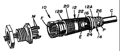
Referring to the drawings and partfculerly to FIGS. 1 to 3, there is
illustrated a first embodiment of a quick disconnect cable connector device,
generaily designated 10, of the present invention for releasably coupling
together
mateable oonventional male and female contact temtinAtions M, F such as
commonly employed on the ends E of waxial cable C and on equipmsnt to which
such cable Is connected. Basically, the cable connector device 10 Includes an
elongated body 12 made of a rigid materfal, such as a fiberqlass reinforced
plastic
material, arid having opposlte first and second ends 12A,1213, and a strain
relief
structure 14 Integrally connected to the first end 12A of the body 12 and made
of
the same fneterial. The body 12 and strain relief structure 14 can be molded
together over the end E of the cable C through employment of coriventional
inJection molding techniques well-known to those of ordinary skill In the art.
Refen'Ing to FIGS. 1 to 4, in the first embodiment, the elongated body 12
- 4
-
CA 02312343 2000-06-21
911-0561
has a substantlally conical-shaped configuration tapering from the second end
128 to the first end 12A. Thus, the boby 12 has an outside diameter at the
first
end 12A which is less than an outside diameter at the second end 12B thereof.
Also, the axial length of the body 12 is substantially greater than the
outside
diameter of the body 12 at its second end 128. The body 12 defines en interior
chamber 16 extending between and open at the first end 12A and second end
128 and receiving the end E of the coaxial cable C therethrough from the first
end
12A to the second end 12B such that the body 12 provides an overmold encasing
the end E of the cable C and also supports at the second end 12B of the
overmold body 12 one of the mateable male and female contact terminations M,
F on the end E of the cabie C.
The body 12 also has an exterior surface 18 circumferentially encircling the
body 12 and having suitable gripping means formed thereon. In one preferred
form, the gripping means on the exterior surface 18 Includes a plurality of
longitudinal ribs 20 spaced apart circumferentialiy and extending
longitudinally
between the first end 12A and the second end 12B of the body 12. A portion of
the longitudinal ribs 20 can be interrupted at location 22 to provide spaoe
for the
applir.ation of the manufacturer's logo on the exterior surface 18 of the body
12.
The gripping means on the exterior surface 18 of the body 12 further includes
a
pair of cinximferenttal ribs 24 spaced apart from one anothar, protruding
outwardly from said exteriorsurface 1 B and oircumFerentially extending about
sald
body 12 at said first end 12A thereof >and adjacent to said strain relief
structure
14. The longltudin4t and circumferential ribs 20, 24 give the exterior surface
18
a rough texture but are smaii in cross-sectional size and thus protrude
outwardly
only slightly from the exterior surface 18 of the body 12. The rough texture
of the
rfbs 20, 24 and the conical shape of the body 12 provide the device 10 with an
ergonomic configuration that aids the user in gripping the device 10 and in
pushing and pulling on the device 10 to assist in the process of coupling and
deooupling the mateable male and female contact terminations M, F to and from
one another.
Referring to FIGS. 1 to 5, the strain reiief stnicture 14 of the cable
connector devlce 10 includes a framework 28 having an annular shape and
forming a passage 28 extending along a longitudinal axis L of the framework 26
-5 -
CA 02312343 2000-06-21
911-0561 '
and aligned with the first end 12A of the body 12. The framework 26 surrounds
and receives through the passage 28 thereof a portion P of the cable C
extending
from the first end 12A of the body 12. The framework 26 has a configuration
which distributes away from the cable portion P at the first end 12A of the
body
s 12 any banding or other forces imposed on the cable C.
More particularly, the frameworic 26 has a plurelity of windows 30 defined
therethrough and spaced apart from each other which provide some minimal
amount of ilexibllity to the strain relief*structure 14 whlch aids in the
distribution
of the bending and other forves away from the cable portton P at the first end
12A
zo of the body 12. The windows 30 have transverse dimensions (or lengths)
extending circumferentlally about the framework 26 and transverse to the
longitudinal axis L of the framework 26. The windows 30 also have longitudinal
dlmensions (or widths) extending along or parallel to the longitudinal axis L
of the
framework 26, The framework 26 also includes a plurality of Interconnected
is longitudinal and transverse support elements 32, 34 defining the windows 30
therebetw en. As can be readily understood In FIG. 5, the transverse
dimensions
of the windows 30A in an inner row thereof are greater than the transverse
dimensions of the windows 308 in an outer row thereof while the transverse
dimensions of all windows 30A, 30B in the inner and outer rows thereof are
20 substantially smaller than the transverse dimensions of the windows 30C in
a
center row thereof. The respective windows 30A, 30C, 30B in the inner, center
arid outer rows thereof are spaced at graduated distances from the first end
12A
of the body 12. The windows 30B of the outer row thereof spaced farther from
the
first end 12A of the body 12 have longer longitudinal dimensions than the
25 wlndows 30A, 30C of the Inner and center mws thereof which are spaoed
closer
to the first end 12A of the body. The windows 30C of the center row thereof
have
a longer longitudinal dimension than the windows 30A of the inner row thereof.
The cortfiguration of the framework 26, as defined by the intenconnected
longitudinal and transverse support elements 32, 34 and the windows 30
30 therebetween, thus eliminates the occurrence of a sharp angular bend oF the
cable C relative to the body 12 at the end 12A thereof that could damage the
cable C and/or Its connection with the body 12.
Referring to FIGS. 6 to 8, there is Illustrated a second embodiment of the
- 6 -'
CA 02312343 2000-06-21
911-0561
elongated body, designated 36, of the cable connector device 10. The body 36
of the second embodiment is similar to the body 12 of the first embodiment in
that
the body 36 has opposite first and second ends 36A, 368 and defines an
interior
chamber 38 open at the first end second ends 36A, 368. Also, Iike the biody
12,
s the body 36 receives the end E of the cable C through the first nd 36A, the
interior chamber 3B and the second end 36B of the body 36 such that the body
36 provides an overmoid encasing the end E of the cable C and also supports at
the second end 368 of the overmold body 36 one of the mateable mate and
female contact terminations M, F on the end E of the cable C. The body 36 of
the
io second embodiment has the same integrally connected strain relief structure
14'
as described above in association with the body 12 of the first embodiment and
both the body 36 and strain relief stnucture 14 are molded using the same
material
and through employment of conventional injection molding techniques well-known
to those of ordinary skill in the art.
15 Unlike the body 12 of the tTrst embodiment, the body 36 of the second
embodiment has a substantially elbow-shaped configuratlon. The body 36 has
a first leg portion 40 extending interioriy from the first end 36A and a
seoond leg
portion 42 extending interioriy from the second end 36B. Each of the first and
second leg portions 40, 42 has a substantially cylindrical configuration. The
20 outside diameter of the first leg portion 40 is less than the diameter of
the second
leg portion 42. The body 36 also has a rear surface portion 44. The rear
surface
portion 44 is formed generally at the juncture of the first and second leg
portions
40, 42. The rear surface portion 44 is substantialiy flat and assists the user
in
pushing on the body 12 in mateably coupling the male and female contact
25 terminations M, F to one another.
The body 36 also has an exterior surface 46 formed on second leg portion
42 adjacent to the second end 36B of the body 36. The exterior surface 46 has
gripping means thereon which indudes a plurality of ribs 48. The ribs 48
extend
transversely on the body 36, paltica.liarly, on top and opposite sides of the
second
30 leg portion 42 and are spaced from the second end 366 of the body 36. The
gripping ribs 48 prefsrably are three in number and extend in spaoed apart
generally parallel relationship to one another. The rib 48A disposed farthest
from
the second end 368 of the body 36 is continuous on the top and opposite sides
- 7 -
CA 02312343 2000-06-21
911-0561
of the second leg portion 42. The ribs 48B and 48C dlsposed progressively
closer to the second end 368 of the body 36 are interrupted at two locations
where the top and opposite sides of the second leg portion 42 come together.
The rib 48B Is farther from the second end 36B than is the rib 48C. Each of
the
ribs 488, 48C have sections on each of the top and opposite sides of the
second
leg portion 42. The rib 48A protrudes outwardly from the exterior surface 46
slightiy farther than each of the ribs 485, 48C, but all of the ribs'48 are
small and
do not protrude to a substarltial degree. The ribs 48 give the user finger
holds tn
pushing end pulling the body 36 in the process of coupling and decoupling the
io mateable male and female contact terminations M. F to and from one another.
It Is thought that the present Invention and its advantages wiil be
understood from the foregoing description and it wlll be apparent that various
changes may be made thereto without departing from its spirit and scope of the
invention or sacrificing all of its material dvantapes, the form hereinbefore
described being merely preferred or exemplary embodiment thereof.
- e -