Note: Descriptions are shown in the official language in which they were submitted.
CA 02316380 2000-06-21
WD 99134465 PCTlCA98I01161
METHOD AND APPARATUS FOR OPERATING AN
ELECTROCH~dICAL FUEL CBLL 1PITH PERIODIC FUEL
STARVATION AT T8E ANODE
Fi~ld Of The Invsntior~
The present invention relates to a method and
apparatus for operating an electrochemical fuel
cell with periodic fuel starvation at the anode.
More particularly, the method comprises
periodically momentarily fuel starving at least a
portion of the anode of an operational fuel cell.
The method and apparatus may be used to improve
fuel cell performance without suspending the
l0 generation of power by the fuel cell.
Haekaround Of The Invention
Electrochemical fuel cells convert reactants,
namely fuel and oxidant fluid streams, to produce
electric power and reaction products. Solid
polymer electrochemical fuel cells generally employ
a membrane electrode assembly ("MEA") comprising a
solid polymer electrolyte or ion-exchange membrane
disposed between two porous electrically conductive
electrode layers. The anode and cathode each
comprise electrocatalyst, which is typically
disposed at the membrane/electrode layer interface,
to induce the desired electrochemical reaction.
At the anode, the fuel moves through the
porous anode layer and is oxidized at the
electrocatalyst to produce protons and electrons.
The protons migrate through the ion exchange
membrane towards the cathode. On the other aide of
the membrane, the oxidant moves through the porous
CA 02316380 2000-06-21
wo s9r~~ess rcTicw~om6i
- 2 -
cathode and reacts with the protons at the cathode
electrocatalyst. The electrons travel from the
anode to the cathode through an external circuit,
producing an electrical current.
Electrochemical fuel cells can operate using
various reactants. For example, the fuel stream
may be substantially pure hydrogen gas, a gaseous
hydrogen-containing reformate stream, or methanol
in a direct methanol fuel cell. The oxidant may be
substantially pure oxygen or a dilute stream such
as air containing oxygen.
The fuel stream may contain impurities which
do not contribute to, and may actually inhibit, the
desired electrochemical reaction. These impurities
may, for example, originate from the fuel stream
supply itself, or may be generated in situ in the
fuel cell, for example, as intermediate species
during the fuel cell reactions. Further,
impurities may enter the fuel stream from elsewhere
in the system. Some of these impurities may be
chemically adsorbed or physically deposited on the
surface of the anode electrocatalyst, blocking the
active electrocatalyst sites and preventing these
portions of~the anode electrocatalyst from inducing
the desired electrochemical fuel oxidation
reaction. Such impurities are known as
electrocatalyst "poisons" and their effect on
electrochemical fuel cells is known as
~~electrocatalyst poisoning". Electrocatalyst
poisoning thus results in reduced fuel cell
performance, where fuel cell performance ie defined
as the voltage output from the cell for a given
current density. Higher performance is associated
y with higher voltage for a given current density or
CA 02316380 2000-06-21
Wrp gg~3~s PCT1CA98/01161
- 3 -
higher current for a given voltage.
In the absence of countermeasures, the
adsorption or deposition of electrocatalyst poisons
may be cumulative, so even minute concentrations of
poisons in a fuel stream, may, over time, result in
a degree of electrocatalyst poisoning which is
detrimental to fuel cell performance.
Reformats streams derived from hydrocarbons or
oxygenated hydrocarbons typically contain a high
concentration of hydrogen fuel, but typically also
contain electrocatalyst poisons such as carbon
monoxide. To reduce the effects of anode
electrocatalyst poisoning, it is known to pre-treat
the fuel supply stream prior to directing it to the
fuel cell. For example, pre-treatment methods may
employ catalytic or other methods to convert carbon
monoxide to carbon dioxide. However, known pre-
treatment methods for reformats streams cannot
efficiently remove 100% of the carbon monoxide.
Even trace amounts less than l0 ppm can eventually
result in electrocatalyst poisoning which causes a
reduction in fuel cell performance.
Substances other than carbon monoxide are also
known to poison fuel cell electrocatalyats.
Depending on the type of fuel and the fuel
processing methods, impurities in the fuel stream
may be present in quantities sufficient to poison
the electrocatalyst and reduce fuel cell
performance. Fuel cell components and other fluid
streams in the fuel cell system may also be a
source of impurities which may result in poisoning
of the electrocatalyst. For example, fuel cell
separator plates are commonly made from graphite.
organic impurities in the graphite may leach out
CA 02316380 2000-06-21
WO 99/34465 PCT/CA98101161
- 5 -
introduce a low concentration of oxygen into the
fuel stream upstream of the fuel cell, as disclosed
by Gottesfeld in United States Patent No.
4,910,099. However, there are several
disadvantages to Gottesfeld's method which
influence fuel cell performance and efficiency.
For example, an oxygen bleed results in parasitic
losses, undesirable localized exothermic reactions
at the anode, and dilution of the fuel stream.
It is apparent from the prior art that there
is a need for an improved method and apparatus for
rejuvenating a fuel cell anode electrocatalyst by
removing poisons therefrom, which does not involve
suspending the availability of the fuel cell to
generate power.
Summary Of The Iavnution
A fuel cell is operated to produce electrical
power for an electrical load by supplying an
oxidant stream to the fuel cell cathode, and a fuel
stream to the fuel cell anode. The present method
comprises periodically momentarily fuel starving at
least a portion of the anode, while continuing to
produce electrical power from the fuel cell.
Typically, when the method is applied, the fuel
cell performance after the momentary starvation is
improved relative to the performance just prior to
the momentary starvation, particularly during
operation on a fuel stream comprising one or more
electrocatalyst poisons. This effect is believed
to be due to oxidation of electrocatalyst poisons,
which is facilitated as the anode potential
increases as occurs during fuel starvation at the
anode. The method may be advantageously applied,
CA 02316380 2000-06-21
WO 99/34465 PCT/CA98/01161
- 6 -
for example, during operation of the fuel cell on
~reformate fuel streams comprising hydrogen (as the
fuel), carbon monoxide and carbon dioxide.
The fuel cell is preferably a solid polymer
fuel cell. The fuel and oxidant streams may be
gaseous or liquid. The fuel cell may, for example,
be a direct methanol fuel cell.
In a first embodiment, the method for
momentarily fuel starving at least a portion of the
fuel cell anode comprises periodically momentarily
interrupting the supply of the fuel stream to the
fuel cell anode. This can be accomplished, for
example, by adjusting a valve upstream of the fuel
cell anode, stopping a fuel supply pump, or
diverting the fuel supply stream away from the fuel
cell anode.
Where the fuel cell is one of a plurality of
fuel cells, for example, arranged in a fuel cell
stack, the method preferably comprises preventing
the simultaneous interruption of the supply of fuel
to each anode of the plurality of fuel cells. This
reduces the fluctuation in electrical power output
from the stack.
The first embodiment of the method may further
comprise closing a valve downstream of the fuel
cell anode substantially simultaneously with the
interruption of supply of the fuel stream to
momentarily prevent the fuel stream from being
exhausted from the fuel cell.
In a second embodiment, the method for
momentarily fuel starving at least a portion of the
fuel cell anode comprises periodically introducing
pulses of a substantially fuel-free fluid into the
fuel stream upstream of the fuel cell anode. The
CA 02316380 2000-06-21
WO 99l3N65 PCT/CA98I01161
_substantially fuel-free fluid moves through the
anode flow field, thereby momentarily fuel starving
successive portions of the anode.
The substantially fuel-free fluid may contain
some fuel, provided the fuel concentration is
sufficiently low to induce momentary fuel
starvation of portions of the anode with which the
fluid is.in is contact, and thereby give the
desired recovery in performance of the fuel cell.
Preferably the substantially fuel-free fluid
contains essentially no fuel and is substantially
unreactive at the fuel cell anode, for example,
nitrogen, argon, helium and hydrocarbons.
Alternatively, the substantially fuel-free fluid
may comprise quantities of components which
participate in and enhance the desired poison
oxidation reactions but are not themselves catalyst
poisons or detrimental to fuel cell performance.
For example, substantially fuel-free fluids
comprising water or oxygen may facilitate the
oxidation of some electrocatalyst poisons. For
example, the exhaust gas from the fuel cell cathode
may be a suitable substantially fuel-free fluid
comprising low concentrations of oxygen.
The fuel and the substantially fuel-free
liquid may both be in the same phase or different
phases. For example, the fuel stream may be a gas
stream and the substantially fuel-free fluid may be
a liquid, or the fuel stream may be a liquid and
the substantially fuel-free fluid pulse may be
gaseous, or the fuel stream and the substantially
fuel-free fluid may both be gaseous or liquid.
Where both streams are liquids it may be preferable
if the substantially fuel-free fluid ie immiscible
CA 02316380 2000-06-21
WO 99/34465 PCT/CA9810116I
_ g -
with the liquid fuel stream. Where the liquid fuel
stream comprises aqueous methanol, a suitable and
convenient substantially fuel-free fluid may be
water.
The method may comprise introducing a
substantially fuel-free fluid pulse which is cooler
than the internal operating temperature of the fuel
cell. In this embodiment, the substantially fuel-
free fluid may act as a coolant for the fuel cell.
Similarly, substantially fuel-free fluid could be
introduced at a temperature higher than the
operating temperature of the fuel cell, in
situations where it is desirable to raise the fuel
cell operating temperature.
The method for introducing the substantially
fluid-free pulse may comprise the steps of
periodically closing a fuel supply valve to stop
the flow of the fuel stream upstream of the fuel
cell and simultaneously opening an interrupt valve
to introduce a pulse of a substantially fuel-free
fluid stream into the fuel stream. In a variation
on this embodiment, the fuel supply stream is
maintained at a lower pressure than the
substantially fuel-free fluid stream, and the
method of introducing the substantially fuel-free
fluid comprises periodically opening an interrupt
valve to introduce a pulse of a substantially fuel-
free fluid stream into the fuel stream.
In a third embodiment, the method for
momentarily fuel starving at least a portion of the
fuel cell anode comprises periodically connecting a
transient electrical load to draw electrical power
from the fuel cell. Preferably, the rate of supply
of the fuel stream to the fuel cell anode is not
CA 02316380 2000-06-21
WO 99134465 PCT/CA98/01161
_ g _
increased in response to the connection of the
transient load, so that fuel in the fuel cell is
consumed at a faster rate than it is supplied and
at least a portion of the anode becomes fuel
S starved. The transient electrical load may
comprise a capacitor which may be used to release
an electrical charge, for example, when the power
demand from the electrical load exceeds the power
output of the fuel cell during times when the fuel
cell is undergoing rejuvenation.
Where the fuel cell is one of a plurality of
fuel cells, for example, arranged in a fuel cell
stack, preferably the periodic connection of the
transient load is not connected to draw electrical
power from all the fuel cells simultaneously.
In any of the embodiments described above the
momentary fuel starvation may be induced at regular
time intervals, for example, by interrupting the
fuel supply, introducing substantially fuel-free
pulses or connecting a transient load at regular
time intervals. Alternatively, the method may
comprising monitoring an operational parameter of
the fuel cell and adjusting the frequency with
which the momentary fuel starvation is induced in
response to the value of the monitored parameter.
Similarly, the duration of the momentary fuel
starvation may be fixed or varied, for example in
response to a monitored operational parameter.
One or both the duration and frequency of the
periodic momentary interruptions may be selected as
a function of the concentration of the catalyst
poisoning species in the fuel stream.
In the above embodiments, it is generally
preferred that cell reversal is avoided. However,
CA 02316380 2000-06-21
wo ~r~ss pc~ric~~ouei
- io -
_embodiment of the method for operating a fuel cell
assembly comprising plurality of fuel cells, may
comprise periodically fuel starving at least one,
but not all, of the fuel cell anodes such that a
momentary cell reversal occurs, while continuing to
generate electrical power from the remaining cells.
Preferably, the fuel starvation is limited so that
the momentary cell reversal does not cause the
oxidation of any of the fuel cell components.
In a first embodiment, a fuel cell apparatus
comprises a fuel supply system for directing a fuel
stream to an anode of the fuel cell, a f low
controller for periodically momentarily
interrupting the supply of the fuel stream to the
anode, and an actuator associated with the flow
controller for controlling the frequency and
duration of the interruptions.
The flow controller may comprise a fuel supply
valve located upstream of the anode, and the
actuator is preferably connected to periodically
partially or preferably fully close the fuel supply
valve to interrupt the fuel supply to the anode.
The fuel cell apparatus may further comprise a fuel
exhaust stream valve located downstream of the
anode which is activated by the actuator (or a
second actuator activated in coordination with the
first actuator) to open and close in coordination
with the fuel supply valve.
The fuel supply system may comprise a pump for
directing a fuel stream to the anode. In this
embodiment, the actuator may, for example, be
connected to periodically deactivate the pump and
thereby interrupt the fuel supply to the anode. A
fuel exhaust stream valve located downstream of the
CA 02316380 2000-06-21
WO 99/34165 PGTlCA98101161
- 11 -
anode may be activated by the actuator in
.coordination With the pump activation to close the
valve when the pump is periodically deactivated,
and open the valve when the pump is re-activated.
The flow controller may comprise a diverter
located upstream of the anode for diverting the
fuel stream away from the anode. The diverter may
be periodically actuated by the actuator.
A sensor may be employed for detecting the
concentration of catalyst poisons in the fuel
stream. The sensor may provide an output signal to
the actuator which adjusts the frequency and/or
duration of 'the interruptions in response to the
sensor output signal.
The fuel cell may comprise a plurality of
independent fuel flow field channels for directing
the fuel stream in contact with the anode. Each
one of the flow field channels directs the fuel
stream to a discrete region of the anode and the
supply of the fuel stream to each one of the
regions can be controlled independently from the
supply of the fuel stream to other ones of the
regions. In this embodiment, selected regions of
the anode can be fuel starved while other regions
continue to contribute to the fuel cell power
output.
In a second embodiment, a fuel cell apparatus
comprises a fuel supply system for directing a fuel
stream to an anode of the fuel cell, a source of a
substantially fuel-free fluid, and a flow
controller for periodically introducing pulses of
the substantially fuel-free fluid into the fuel
stream upstream of the fuel cell anode. The flow
controller may comprise an interrupt valve for
CA 02316380 2000-06-21
WO 99134465 PCT/CA98101161
- 12 -
controlling the introduction of the substantially
fuel-free fluid stream into the fuel stream.
In one example of such an embodiment, the source of
substantially fuel-free fluid may include the
oxidant exhaust stream from the fuel cell. In this
embodiment, the interrupt valve may be fluidly
connected to an oxidant stream outlet of the fuel
cell.
In a third embodiment, a fuel cell apparatus
1o comprises a transient electrical load which is
selectively electrically connected to draw
electrical power from the fuel cell. A switch
periodically momentarily electrically connects the
transient electrical load to draw electrical power
from the fuel cell. An actuator associated with
the switch controls the frequency and duration of
the electrical connection. The transient load may
comprise a capacitor for storing an electrical
charge which can be released to the electrical
load.
The embodiments described above may be used to
improve fuel cell performance and increase the
service life of an electrochemical fuel cell.
Briaf D~ecriation Of The DrawiaQs
The advantages, nature and additional features
of the invention will become more apparent from the
following description, together with the
accompanying drawings, in which:
3o FIG. 1 is an exploded view of a conventional
fuel cell stack (prior art);
FIGS. 2 and 4 through 7 are schematic
illustrations of embodiments of the apparatus of
the invention;
CA 02316380 2000-06-21
WO 99/34465 PGT/CA98/01161
- 13 -
_ FIG. 3 is a diagram of a fuel flow field and
anode depicting substantially fuel-free fluid
pulses moving through the fuel flow field in the
fuel stream;
FIG. 8 is a graph plotting average cell
voltage against time, showing the effect of
periodic fuel supply interruptions; and
FIG. 9 is a graph plotting average cell
voltage against time, showing the effect of
periodic fuel supply interruptions with coordinated
introductions of pulses of a substantially fuel-
free fluid.
Detailed Deecri~tion of Preferred Embodiments
The present invention teaches a method and
apparatus for operating an electrochemical fuel
cell with periodic fuel starvation at the anode
while not suspending the generation of power. In
the context of this disclosure, fuel starvation is
defined as a reduction in fuel supply to the anode
electrocatalyst Which results in the anode
potential increasing (that is, moving towards the
positive cathode potential). It is believed that
an increased anode potential results in the
oxidation and removal of poisons from the fuel
starved portion of the anode electrocatalyst.
FIG. 1 illustrates, in exploded view, a solid
polymer fuel cell stack 10, including a pair of end
plate assemblies 15, 20 and a plurality of fuel
cell assemblies 25. Tie rods 30 extend between end
plate assemblies 15 and 20 to retain and secure
stack assembly 10 in its assembled state with
fastening nuts 32. Springs 34 threaded on tie rods
30 interposed between fastening nuts 32 and end
CA 02316380 2000-06-21
W O 99134465 PCT/CA98/01161
- 14 -
plate 20 apply resilient compressive force to stack
l0 in the longitudinal direction. Reactant and
coolant fluid streams are supplied to and exhausted
from internal manifolds and passages in stack 10
via inlet and outlet ports (not shown in FIG. 1? in
end plate 15. As shown by the exploded portion of
FIG. 1, each fuel cell assembly 25 includes an
anode flow field plate 35, a cathode flow field
plate 40, and an MEA 45 interposed between plates
35 and 40.
Plates 35 and 40 act as current collectors and
provide a fluid barrier for separating reactant
fluids supplied to the anode and cathode. At the
interface between MEA 45 and plates 35 and 40,
fluid flow fields 5o direct the reactant fluids to
the electrodes. Fluid flow field 50 typically
comprises a plurality of fluid flow channels formed
in the major surfaces of plates 35 and 40 facing
MEA 45.
One purpose of fluid flow field 50 is to
distribute the reactant fluid to the entire surface
of the respective electrodes, namely the anode on
the fuel side and the cathode on the oxidant side.
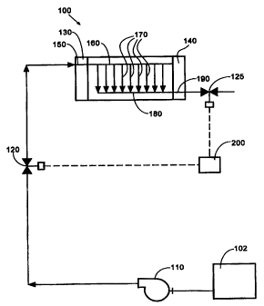
FIGS. 2 and 4 through 7 are schematic
depictions of various examples of apparatus which
may be used to periodically momentarily fuel starve
at least a portion of the anodes in fuel cell stack
100. Stack 100 includes end plates 130, 140, a
fuel inlet port 150 in end plate 130, and a fuel
supply manifold 160 for supplying a fuel stream to
a plurality of individual fuel cells.
Fuel flow fields associated with each fuel
cell are represented by lines 170. A fuel exhaust
manifold 180 removes the fuel depleted stream from
CA 02316380 2000-06-21
WO 99/34465 PCTICA9S/01161
- 15 -
stack 100 through fuel outlet port 190 in end plate
140. Stack 100 also has a similar arrangement of
ports, manifolds and flow fields (not shown) for
supplying and exhausting an oxidant stream to and
from stack 100.
The fuel stream is directed to stack 100 from
a fuel source such as a reservoir, storage tank
102, pressurized storage vessel 105 (see FIG. 5),
or fuel processor, for example, comprising a
reformer. In some embodiments, (see FIGS. 2, 4 and
6), especially when the fuel source is not
pressurized, a pump 110 may be used to direct the
fuel stream to stack 100.
Fuel supply valve 120 controls the supply of
fuel to stack 100. Fuel supply to stack 100 may be
interrupted by closing fuel supply valve 120.
Referring now to FIG. 2, when fuel cell stack
10o is connected and operating to deliver
electrical power to a load, and fuel supply valve
120 is closed or~adjusted to reduce the rate of
supply of fuel to less than that demanded to
satisfy the load, the fuel cell anodes become fuel
starved. The cell voltage drops and the anode
potential increases as the fuel inside stack 100 is
consumed by the electrochemical reaction which is
induced to supply electrical current to the
electrical load. In the preferred method, the
increase in anode potential results in the
oxidation of electrocatalyst poisons. The oxidized
poisons become part of the fuel exhaust stream.
Preferably, the extent to which the anode is fuel
starved and the resultant cell voltage drop is
controlled by opening fuel supply valve 120 before
cell reversal occurs. Cell reversal occurs when
CA 02316380 2000-06-21
WO 99/34465 PCT/CA98/01161
- 16 -
the anode potential increases and becomes more
.positive than the cathode potential, resulting in a
negative cell voltage. In this situation the cell
is consuming, rather than producing, electrical
power. Momentary instances of slight cell reversal
may not damage the fuel cell, but prolonged cell
reversal or large negative cell voltages can cause
permanent damage. Cell reversal may result~in the
production of oxygen at the anode through the
l0 oxidation of water. Initially, the oxygen produced
by cell reversal may momentarily assist in the
oxidation of electrocatalyst poisons, but after a
more prolonged period, permanent damage may be
caused by the oxidation of some of the fuel cell
components. Accordingly, it is preferable to
control the duration and frequency of the periodic
fuel supply interruptions, using controller 200, to
avoid cell reversal while still achieving the
desired removal of poisons from the fuel cell
electrocatalyst.
The preferred duration depends upon many
factors. For example, these factors include the
type and concentration of the electrocatalyst
poisons, the cell design, the physical
characteristics of the fuel cell, the fuel flow
rate, reactant pressure, and reactant
stoichiometry. The duration of the periodic fuel
supply interruptions may be, for example, increased
until the fuel cell almost ceases to produce useful
electrical power or reaches a condition where cell
reversal is about to occur. Fuel cell operating
parameters which are indicators of such conditions
may be monitored to determine when these limits are
approached. The duration of fuel starvation may be
CA 02316380 2000-06-21
wo s9rsa~s pcr~c,~aiom6i
- m -
adjusted in response to one. or more monitored fuel
,cell operating parameters to enhance poison removal
while preventing permanent damage to the fuel cell
caused by cell reversal. Suitable operating
parameters may include cell voltage, current, power
output, poison concentration in the fuel stream and
temperature.
With respect to frequency, the interruptions
may be spaced at fixed time intervals or variable
time intervals which are adjusted according to
factors such as, for example, the concentration of
poisons to which the anode electrocatalyst is
exposed, and the configuration of the flow field.
For example, for fuel cells subjected to lower
poison concentrations, it is possible to lengthen
the intervals between periodic fuel supply
interruptions.
In some cases the balance between the duration
and frequency of interruptions should be considered
in view of the particular application for which the
fuel cell is used. For example, some applications
are more sensitive to one of either the magnitude
or frequency of power fluctuations. That is, if
the fuel cell is used for an application which is
sensitive to the frequency of power fluctuations,
it may be desirable to periodically starve the fuel
cell for longer durations at a lower frequency.
Conversely, other applications may be more
sensitive to the magnitude of power fluctuations,
in which case it may be preferable to increase the
frequency of fuel supply interruptions and decrease
the duration of each periodic interruption.
Closing fuel supply valve 120 may cause an
increase in the transmembrane pressure differential
CA 02316380 2000-06-21
wa ~r34~s rcr~c~~loii6i
1B _
across the MEAs. To avoid damage to the ion
.exchange membrane, preferably controller 200 opens
and closes fuel exhaust valve 125 substantially
simultaneously with fuel supply valve 120. In this
way, the anode will be fuel starved once the fuel
remaining in stack 100 is consumed, but there will
not be a significant sudden pressure drop on the
fuel side of the MEA.
In another embodiment of an apparatus, the
l0 effect of power output interruptions can be reduced
by dividing the electrochemically active areas of
each fuel cell into separate regions, with each
region having a separate fuel flow field and fuel
supply valve 120. Then the interruption of the
fuel supply to different regions of the same fuel
cell can be staggered, so that not all portions of
the active area are starved at the same time.
In some embodiments, fuel supply manifold 160
may comprise a mechanism, such as for example a
rotary valve disposed within manifold 160, for
controlling the distribution of fuel to the
individual fuel cells. Preferably, the rotary
valve controls the fuel supply stream to prevent
the simultaneous interruption of the fuel supply
stream to all of the fuel cells in stack 100.
In applications where a plurality of fuel cell
stacks are used in combination to supply electrical
power it is advantageous to stagger the timing for
the fuel interruptions to each stack to reduce the
effect of the interruptions on total power output.
In variations of the embodiment illustrated in
FIG. 2, periodic interruptions in the supply of
fuel to stack 100 may be accomplished without using
a fuel supply valve 120, by using controller 200 to
CA 02316380 2000-06-21
Wrp g9~s PCT/CA98/01161
- 19 -
periodically stop pump 110 thereby stopping the
~~~supply of fuel to stack 100, or by periodically
temporarily diverting the fuel stream away from the
stack fuel inlet port 150.
In other embodiments of the method, localized
starvation of the anode is accomplished by
introducing substantially fuel-free fluid pulses
250 into the fuel stream using apparatus such as
that illustrated in FIG. 3. In operation, with
reference to the embodiment depicted by FIGS. 3 and
4, fuel supply valve 120 is open and interrupt
valve 210 is closed. Periodically interrupt valve
210 is momentarily opened while controller 200
synchronously closes fuel supply valve 120, thereby
introducing substantially fuel-free fluid pulses
250 into fuel stream 260. The substantially fuel-
free fluid may be introduced from a fluid source
such as vessel 215 in FIG. 4. In these
embodiments, controller 200 coordinates the
operation of valves 120 and 210 so that they remain
in opposite open or closed positions. An advantage
of this approach is that it is less likely to
create a sudden change in transmembrane pressure
differential across the MBAs compared to
interrupting the fuel supply as described above.
Preferably, the substantially fuel-free fluid
stream 250 is introduced into the fuel stream 260
at substantially the same pressure that the fuel
stream is supplied to stack 100. It is believed
that this promotes the flow of a discrete
substantially fuel-free fluid pulse through the
fuel side flow field. A large pressure
differential between the fuel stream and the
substantially fuel-free fluid stream may cause the
CA 02316380 2000-06-21
WO 99/34465 PCTICA98/01161
- 20 -
higher pressure fluid to disperse into the lower
pressure fluid, reducing the localized starvation
effect.
The flow field design may also affect the
S extent to which the fluid streams mix as they move
through the fuel cells. It may be desirable to
control the pressures and design the flow field to
reduce mixing Which may inhibit the formation of
localized fuel starvation conditions at the anode.
The fluid pressures need not be precisely
matched. In some embodiments it may be desirable
for the substantially fuel-free fluid to be at a
slightly higher pressure than the fuel stream. An
advantage of this is that the alight pressure
differential will prevent fuel from contaminating
the substantially fuel-free fluid source, and the
substantially fuel-free fluid can be introduced
into the fuel stream by opening interrupt valve
210, without the necessity of closing fuel supply
~ valve 120.
The volume of the substantially fuel-free
fluid pulses 250 can be as much as the open volume
of fuel flow field 290 and porous anode 270.
However, preferably, the volume of substantially
fuel-free fluid pulses 250 is much less than the
open volume of fuel flow field 290 and porous anode
270, thereby ensuring that the majority of each
anode 270 remains saturated with fuel and
electrochemically active. The electrochemically
active areas continue to be available to produce an
electrical current while only successive localized
portions 280 of the active area are momentarily
fuel starved to oxidize and remove electrocatalyst
poisons. Using this embodiment it is possible to
CA 02316380 2000-06-21
wo ~r~~s rcTic~9~om6~
- 21 -
_reduce cell voltage fluctuations which may occur
when the entire anode 270 is simultaneously fuel
starved. Accordingly, it is desirable for the
volume of substantially fuel-free fluid pulses 250
to be less than the open channel volume of fuel
flow field 290.
A variety of gases or liquids are suitable for
use as the substantially fuel-free fluid. The
choice of substantially fuel-free fluid depends
upon factors such as cost, compatibility,
effectiveness; and availability of the fluid
elsewhere in the fuel cell system. The
substantially fuel-free fluid may be unreactive or
may comprise reactive components which participate
in and enhance the desired poison oxidation
reactions but are not themselves catalyst poisons,
for example, water and/or traces of oxygen may
participate in and enhance the oxidation of some
poisons. The preferred substantially fuel-free
fluid may depend upon the nature of the anode
catalyst and the poison to be oxidized.
The fuel stream and the substantially fuel-
free liquid may be in different phases. For
example, the fuel stream could be gaseous hydrogen
or reformate and the substantially fuel-free fluid
could be liquid water. In conventional fuel cells,
it is considered important to manage water inside
the fuel to sufficiently hydrate the membrane and
avoid two phase flow since water in the fuel stream
inhibits the diffusion of fuel to the anode.
According to the present method, an object of the
method is to inhibit the supply of fuel to starve
at least a portion of the anode.
FIG. 5 shows stack 100 having an oxidant inlet
CA 02316380 2000-06-21
WO 99/34465 PCTlCA98/01161
- 22 -
192, for directing an oxidant stream to the
~.cathodes of fuel cell in stack 100, and an oxidant
exhaust outlet 194. In the embodiment depicted by
FIG. 5, interrupt valve 220 is positioned on a
fluid line which connects oxidant outlet 194 with a
stack fuel supply system. In operation, fuel
supply valve 120 is periodically momentarily closed
while interrupt valve 220 is periodically
momentarily opened to introduce pulses of oxidant
exhaust stream (from the fuel cell cathodes) into
the fuel flow fields. An advantage of utilizing
the oxidant exhaust stream as the substantially
fuel-free fluid is that it typically contains some
residual oxygen which can help in the oxidation and
removal of poisons from the anode. The oxidant
exhaust stream also typically contains moisture
which is useful for humidifying the anode and the
water may also participate in the oxidation
reactions which result in the oxidation and.removal
of poisons from the anode. Yet another advantage
of utilizing the oxidant exhaust stream is that
this fluid stream is already present in the fuel
cell system, so there is no need to provide a
separate substantially fuel-free fluid source.
Other fluid streams present in the fuel cell
system may be suitable for use as the substantially
fuel-free fluid (for example, process streams, and
burner exhaust gases). A process stream such as
methane may be diverted to stack 100, from upstream
of the reformer, to act as the substantially fuel-
free fluid. Alternatively, fuel cell systems
employing reformers typically use a burner as part
of the reforming apparatus. The reforming process
may use fuel cell oxidant and fuel exhaust streams
CA 02316380 2000-06-21
WO 99/34465 PCT/CA98/01161
- 23 -
as combustion gases. After combustion, the burner
exhaust stream may be suitable for use as the
substantially fuel-free fluid. Also the exhaust
stream from the anode, which with dilute fuel
streams has a substantially lower fuel content than
the inlet fuel stream, may be suitable.
In operation, using the embodiment of FIG. 6,
a continuous supply of substantially fuel-free
liquid, such as water is added to and mixed with a
liquid fuel stream comprising, for example,
methanol in a direct methanol fuel cell system. A
static mixer 230 may be used to improve the mixing
of the two liquids. Check valve 240 prevents fuel
from contaminating the substantially fuel-free
liquid. Fuel supply valve 120 is periodically
momentarily closed, so that pulses of only the
substantially fuel-free liquid are introduced into
the fuel stream which is directed to stack 100.
An advantage of using a substantially fuel-
free fluid comprising water with non-aqueous
reactant streams is that it will also hydrate the
membrane and reduce the need for humidifying the
reactant streams.
In other embodiments, the method may also be
used to cool stack 100 by introducing a fluid which
is cooler than stack 100 as the substantially fuel-
free fluid pulse. An advantage of using a coolant
as the substantially fuel-free fluid is that it may
reduce or eliminate the need for separate cooling
plates and channels, thereby increasing the power
density of the fuel cell stack. Further, if the
cooling function is combined with the fuel supply
system this reduces the complexity of the overall
fuel cell system. Where it is anticipated that the
CA 02316380 2000-06-21
WO 99!31465 PCTICA98/01161
- 24 -
fuel cell will be subjected to an operating
~~environment where ambient temperatures will be less
than 0°C, a non-corrosive substantially fuel-free
cooling fluid with a freezing point lower than that
of water may be preferred.
Controller 200 is shown in all of the
illustrated embodiments. Controller 200 controls
the interruptions of the fuel supply stream by
controlling both the opening and closing of valves,
l0 or the operation of pump 110. In one embodiment,
controller 200 comprises a timer which causes
controller 200 to periodically open and close fuel
supply valve 120 and/or interrupt valve 210, at
regularly spaced intervals. In other embodiments,
controller 200 responds to monitored operating
parameters such as cell performance to govern the
intervals between interruptions in the fuel supply
and the duration of such interruptions. The
monitored operating parameters may include any of
the fuel cell operating parameters described
herein.
The duration of the fuel supply interruptions
may be of fixed length or controller 200 may close
fuel supply valve 120 until fuel starvation
conditions are momentarily reached in at least a
portion of the anodes in stack 100. Controller 200
may also control interrupt valve 210 in
coordination with fuel supply valve 120 so that
when fuel supply valve 120 is opened, interrupt
valve 210 is closed, and vice versa.
In the embodiments of FIGS. 4 and 5, fuel
supply valve 120 may not be necessary, for example,
if the pressure of the substantially fuel-free
fluid is higher than the pressure of the fuel
CA 02316380 2001-OB-28
-25 -
stream at the point of introduction. Then only
interrupt valve 210 may be needed to introduce the
higher pressure fluid into stack 100, thus
interrupting the fuel supply stream.
FIG. 7 depicts a stack 100 which is connected
to electrical load 300. In the embodiment
illustrated by FIa. 7, the fuel cell anodes in
stack 100 are fuel starved by operating switch 310
to connect transient load 320 to stack 100, without
correspondingly increasing the rate of fuel supply
to the anode. Transient load 320 demands
electrical current which causes fuel in stack 100
to be consumed more rapidly than fuel is supplied.
The frequency and duration of the fuel starvation
can be controlled, as with the other embodiments by
a controller (not shown), except that in this
embodiment the controller operates switch 310.
The controller may be used to periodically
operate switch 310 at regular or variable time
intervals. One or more operating parameters of the
fuel cell may be monitored to determine when the
controller will automatically operate switch 310.
The same, or additional operating parameters may be
monitored to determine how long transient load 320
is connected to receive electrical power from stack
100.
The power drawn by transient load 320 may be
variable so that the severity of the fuel
starvation is adjustable.
The transient load may comprise a capacitor
which is connected in parallel so that an
electrical charge may be released to power load 300
when fuel cell power output is reduced by
electrocatalyst poisoning or rejuvenation cycles.
CA 02316380 2006-06-20
;~6Gft~1
$~ 11~4T6
R O~R~'t~~
-26 -
~Lg i
FIG. 8 is a graph of average cell voltage
plotted against time for a 8allard Mark 8 fuel cell
stack supplied with a reformats fuel stream having a
composition of 75% hydrogen. 25% carboy dioxide and
trace amounts of impurities, including poisons (e. g.
20 ppm or 100 ppm carbon monoxide). The fuel cell
was operating at a current density of 0.646 amps per
em'. The reformats fuel stream supply to the stack
was interrupted for 1 second every 18 seconds by
closing a fuel supply valve. FIG. 8 shows that
after periodic momentary fuel starvation cycles the
fuel cell performance was restored sad enhanced. It
is believed that the enhanced fuel call performance
was the result of electrocatalyst rejuvenation
caused by the removal of poisons from the
electrocatalyst.
As shows by plots A sad H, the periodic
momentary fuel atarvatioa cycles caused momentary
decreases is the cell voltage. Plot A represents
data obtained from an operating fuel cell supplied
with a reformats fuel stream containing 10 ppm
carbon monoxide. The average cell voltage with the
voltage dips taken into account was 0.673 V. Plot H
(dotted lines) represents data obtained from an
operating fuel cell supplied with a refarmate fuel
stream containing 100 ppm carboy monoxide. At 100
ppm carbon monoxide, the average cell voltage with
the voltage dips taken into account was 0.660 V.
However, the data from both plots A and B show
that cell voltage remained positive, thereby
avoiding the problem of cell reversal. Therefore,
FIG. 8 shows that it ie possible, using an
apparatus such as that illustrated in FIG. 2, to
CA 02316380 2001-OB-2A
-27 -
periodically starve the fuel cell and remove poisons
from the electrocatalyat while still generating a
continuous supply of power.
$RAMPLE 2
FIG. 9 is a plot of average cell voltage
plotted against time for a single cell Ballard MkSE
fuel cell using as the anode catalyst a
platinum/ruthenium mixture, where nitrogen pulses
were introduced into the fuel stream directed
through the fuel flow field. The reformate fuel
stream included 72~ hydrogen, 19~ carbon dioxide
and 40 ppm carbon monoxide. The fuel cell was
operating at a current density of 0.538 amps per cm~.
The fuel supply was periodically interrupted and
nitrogen pulses were introduced for 0.05 second
durations at 5 second intervals. With reference to
FIG. 9, Plot C is a plot of the average cell
voltage, with high and low fluctuations taken into
account. Plot D is a plot of the upper performance
limit (i.e. peak cell voltage). Plot E is a plot of
the lower performance limit. By using shorter
interruptions, it is believed that, substantially
fuel-free fluid pulses moving through the flow field
result in localized fuel starved portions of the
anode, while the majority of the anode remains
electrochemically active. The difference between
the upper and lower performance limits is about 0.08
volts. It is believed that this is the reason for
the reduction in the magnitude of cell voltage
fluctuations, compared to FIG. 8 where average cell
voltage fluctuated by approximately 0.5 volts between
a high of about 0.7 volts and a low of about 0.2
CA 02316380 2000-06-21
WO g9PCT/CA9SI~1161
- 28 -
volts.
While particular elements, embodiments and
applications of the present invention have been
shown and described, it will be understood, of
course, that the invention is not limited thereto
since modifications may be made by those skilled in
the art, particularly in light of the foregoing
teachings. It is therefore contemplated by the
appended claims to cover such modifications which
incorporate those features coming within the spirit
and scope of the invention.