Note: Descriptions are shown in the official language in which they were submitted.
CA 02324915 2000-10-31
P-4350
FOR: ELECTRONIC MEDICAL DELIVERY PEN HAVING
A MULTIFUNCTION ACTUATOR
BACKGROUND OF THE INVENTION
1. Field of the Invention
The subject invention relates to an improved electronic medication delivery
pen.
2. Description of Related Art
Home diabetes therapy requires the patient to carry out a prescribed regimen
that
involves self-testing blood glucose levels and administering an appropriate
dose of insulin.
Insulin has traditionally been injected by a hypodermic syringe, which suffers
from
numerous drawbacks. For example, syringes are not preloaded with medication,
requiring
the user to carry a separate medical vial. Syringes also require a degree of
dexterity and
sufficient visual acuity on the part of the patient to line up the needle of
the syringe with
the rubber septum on the medical vial and to ensure that the syringe is loaded
with the
proper dosage. As a result, unintentional needle pricks commonly occur.
To overcome the drawbacks of syringes, medication delivery pens have been
developed,' which facilitate the self-administration of medication such as
insulin. Such
delivery pens use prepackaged insulin and may be used repeatedly until the
medication is
exhausted. Mechanical and electronic pens are available. Electronic pens
incorporate
-1-
-- -- --- ------ - - - ------
CA 02324915 2000-10-31
electronic circuitry that sets and/or indicates the appropriate dosage of
insulin and stores
data for subsequent downloading such as the time, date, amount of medication
injected,
etc.
While electronic pens that mechanically simplify the device have been
proposed, it
has been found that there remains a need for additional features and
improvements that
further utilize the electronic capabilities of the pen. For example, it would
be desirable to
automatically determine the amount of insulin that remains in a cartridge from
which one
or more dosages of medication have been delivered. Likewise, it would be
desirable to
1o automatically determine the size of the cartridge that is installed in the
pen as well as the
type of inedication contained in the cartridge, thus allowing many different
types of
cartridges to be used in a single pen while reducing the likelihood of user
error resulting
from misidentifying the cartridge or manually entering incorrect information
into the pen.
SUMMARY OF THE INVENTION
The subject invention relates to an electronic medication delivery pen in
which the
value of different modes such as time and date modes are changed by the
actuator when the
actuator is disengaged from the drive mechanism of the pen.
In accordance with the present invention, a medication delivery pen includes a
housing having opposing proximal and distal ends. An actuator is disposed in
the proximal
end of the housing for setting and administering a dosage of medication. The
pen also
includes a medication-containing cartridge assembly having a cartridge with a
pierceably
sealed distal end, an open proximal end removably attachable to the distal end
of the
housing, and a piston in sliding fluid tight engagement within the cartridge.
A drive
mechanism is coupled between the actuator and the cartridge to exert an axial
force on the
piston to inject the set dosage of medication. The actuator triggers the drive
mechanism to
administer the injection of medication held in the cartridge. A processor is
coupled to the
actuator to determine a value equal to the dosage set by the actuator. A
memory device is
coupled to the processor to store at least the dosage value determined by the
processor. A
display is located on the housing and coupled to the processor for displaying
information
-2-
CA 02324915 2000-10-31
provided by the processor. In a first state the actuator engages with the
drive mechanism to
deliver the medication and in a second state is disengaged from the drive
mechanism. In its
second state, the actuator serves as a user adjustable input for changing and
setting mode
parameters of at least one preselected mode of the pen.
In some embodiments of the invention the actuator includes a rotatable knob
for
setting the dosage of medication. The rotatable knob also serves as the user
adjustable
input when the actuator is in the second state. The rotatable knob may be
rotated when in
the second state for changing and setting the mode parameters. Other user-
inputs that may
be provided include a user-activatable mode button located on the housing for
selecting the
preselected mode of the pen from among multiple modes such as a time and date
mode,
and an eject button for selectively alternating between the first and second
states of the
actuator.
In accordance with one aspect of the invention, the medication delivery pen
also
includes a sensor coupled to the processor for detecting status information
pertaining to the
drive mechanism to determine a quantity of medication remaining in the
cartridge. Such
status information may include, for example, the linear position of a
leadscrew that forms
part of the drive mechanism.
In accordance with another aspect of the invention, the cartridge has an
encoded
portion which identifies at least one characteristic of the cartridge. A
sensor is coupled to
the processor for detecting the encoded portion of the cartridge so that the
processor can
determine the corresponding characteristic of the cartridge. The
characteristic of the
cartridge that is determined from the encoded portion may be the type of
medication in the
cartridge or the size of the cartridge, for example. The encoded portion of
the cartridge
may be a color code.
BRIEF DESCRIPTION OF THE DRAWINGS
FIG. 1 is a perspective view of a medication delivery pen of the subject
invention;
-3-
CA 02324915 2000-10-31
FIG. 2 is a an exploded perspective view of one embodiment of a drive
mechanism
that may be used in the pen shown in FIG. 1;
FIG. 3 is a perspective view of the medication delivery pen shown in FIG. I
with
the cartridge retainer removed;
FIG. 4 is an exploded perspective view of the medication delivery pen shown in
FIG. 1 with the cartridge retainer removed;
FIG. 5 is another perspective view of the medication delivery pen shown in
FIG. 1
with the cartridge retainer attached and locked onto the upper body;
FIG. 6 is a simplified block diagram of the inedication delivery pen shown in
FIG.
1 showing the electrical communication paths between components; and
FIG. 7 shows a simplified diagram of a medication cartridge located in the
cartridge retainer in which the cartridge includes a color code that is
detected by a sensor
via a light pipe or light guide situated in the cartridge retainer.
DETAILED DESCRIPTION
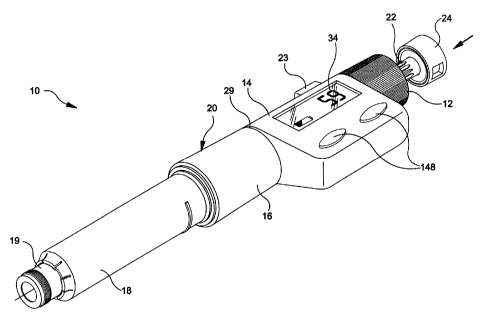
FIG. 1 shows a medication delivery pen in accordance with the present
invention.
The medication delivery pen includes a rotatable adjusting knob 12, a push
button 24, an
eject button 23, an upper body 14, a center body 16, and a medication
cartridge retainer 18.
Rotatable adjusting knob 12, eject button 23, and push button 24 are
operatively coupled to
a drive mechanism (see FIG. 2) located in upper and center bodies 14 and 16.
Cartridge
retainer 18 is adapted for receiving a medication cartridge of the type
described below. The
cartridge retainer 18 is coupled to an end of center body 16 so that the drive
mechanism is
operatively coupled to the medication cartridge.
-4-
CA 02324915 2000-10-31
As shown in FIG. 2, cartridge retainer 18 is adapted for receiving a cartridge
46 of
the type including an internal piston 46b and a pierceable seal 46a at one end
thereof. An
end cap 19 is inserted through cartridge retainer 18 to extend from a distal
end of cartridge
retainer 18. A needle assembly 50 is detachably coupled to end cap 19 by
threads 19a,
friction, or the like. Needle assembly is disposable so that the medication
delivery pen can
be used multiple times. In some cases only the needle 50b itself may be
disposable.
When in the inject mode, the drive mechanism serves to translate the
rotational
displacement of adjusting knob 12 into a corresponding displacement of lead
screw 26 via
1o rotation of plunger 22 and half nuts 28. Push button 24 is then depressed a
fixed distance
so that the lead screw 26 contacts the piston 46b, displacing the piston 46b
by a distance
equal to the displacement of lead screw 26 so that fluid within cartridge 46
is forced
through needle assembly 50. It should be noted that while FIG. 2 shows the
details of one
embodiment of a drive mechanism that may be employed in the present invention,
this
drive mechanism is shown for illustrative purposes only. More generally, the
inventive
medication delivery pen may employ many different types of drive mechanisms.
Referring again to Figs. 2, and 3-5 a plunger 22 is at least partially
positioned
within the portion of housing 20 defined by adjusting knob 12, upper body 14
and center
body 16. Plunger 22 includes a hollow, substantially cylindrical body 22a
including a
band of radially projecting splines 22b extending outwardly therefrom. A pair
of opposing
projections 22c extend radially inwardly from the distal end of the
cylindrical body 22a.
As shown in Fig. 5, the proximal end of plunger 22 is secured to a rotatable
push button
24. Push button 24 fits within adjusting knob 12 when plunger 22 is fully
inserted within
housing 20.
A lead screw 26 is positioned within and coaxially with plunger 22 and
includes an
enlarged distal end 26a and a tapered proximal end 26b, connected by an
elongate threaded
body 26c. A pair of longitudinal grooves 26d are formed within threaded body
26c and
receive the radially inwardly extending projections 22c of plunger 22. Lead
screw 26 is
accordingly rotatable with plunger 22 and capable of sliding axially with
respect to plunger
22.
-5-
CA 02324915 2000-10-31
A pair of half-nuts 28 are positioned within center body 16, with each half-
nut 28
including a semi-cylindrical body portion 28a and a radially enlarged end
portion 28b. The
distal end of each half-nut 28 includes threads 28c that are used to
threadably engage with
lead screw 26 and the proximal end of each half-nut 28 includes a pivot shaft
28d that
receives a metal pin 28e to provide an axis about which each half-nut 28 can
pivot. Metal
pins 28e inserted in each pivot shaft 28d also provide more definite control
over the dose
setting operation, described below, and prevent skewing of half nuts 28 on
threaded lead
screw 26. Body portions 28a of half-nuts 28 are positioned at least partially
within a
locking ring 30 having a hollow, generally cylindrical body portion 30a
defining a
generally elliptical passage 30e for receiving half-nuts 28. A distal end 30b
of locking ring
30 is radially enlarged and includes a pair of angular projections 30c that
extend axially
from the distal end of locking ring 30 and the side of locking ring 30
includes a pair of pins
30d. The proximal end 18b of cartridge retainer 18 includes a pair of angular
projections
18c that are spaced to receive angular projections 30c when cartridge retainer
18 is
mounted on housing 20, which is described further below.
A helical coil spring 32 is positioned over locking ring 30 and half-nuts 28
and
through locking sleeve 31, with one end of coil spring 32 bearing against the
radially
enlarged portions 28b of half-nuts 28 while the opposite end of coil spring 32
bears against
the radially enlarged distal end 30b of locking ring 30. Distal end 30b of
locking ring 30
mounts within center body 16 which also receives finishing ring 29. The
proximal end
portion 28b of half-nuts 28 abut splines 22b of plunger 22.
Locking ring 30 is slidably mounted within locking sleeve 31 such that the
pair of
pins 30d on locking ring 30 are mounted and travel within slot 31a at a distal
end of
locking sleeve 31. With this structure locking ring 30 is axially movable
within locking
sleeve 31 but rotates with locking sleeve 31. Locking sleeve 31 also includes
a pair of L-
shaped grooves 31b that slidably receive each of the shafts 28d on half-nuts
28. Each pivot
shaft 28d in conjunction with its respective L-shaped groove 31b on locking
sleeve 31 and
a long groove 16c within center body 16 provides a mechanism that prevents the
removal
of cartridge retainer 18 and cartridge 46 from housing 20, unless injector
button 24 is in a
-6-
CA 02324915 2000-10-31
down or loading position. This feature is more clearly shown in Figs. 4 and 5.
In Fig. 4
injector button 24 is in the down or loading position and device 10 is in the
proper position
for receiving cartridge retainer 18 and, in particular, lugs 18a can enter
slot 16a of center
body 16. As shown in Fig. 4, locking ring 30 is oriented so that tabs 30c do
not block
access to slot 16a and in this orientation pivot shafts 28d of half-nuts 28
are located in
notches 31 e at the end of each lower leg 31 d of L-shaped groove 31 b. After
a cartridge 46
has been loaded into cartridge retainer 18, cartridge retainer 18 is mated
with center
housing 16 such that lugs 18a enter slot 16a. Then, as shown in Fig. 5,
cartridge retainer
18 is rotated in a clockwise direction such that lugs 18a drive tabs 30c in a
clockwise
l o direction which moves locking sleeve 31 and causes pivot shaft 28d to
slide out of each
notch 31 e and into each leg 31 d.of each L-shaped groove 31b. At this point,
spring 32
drives half-nuts 28 in the proximal direction to extend injector button 24
from the proximal
end of assembly 10, if the eject button 23 is depressed.
Referring to FIG. 6, a microprocessor 32 is located in upper body 14. The
microprocessor 32 determines the dosage of medication to be injected based
upon the
number of rotations of adjusting knob 12 as determined by a dosage sensor 160.
Dosage
sensor 160 may be any appropriate mechanism for determining the number of
rotations,
whether complete or incremental, that adjusting knob 12 undergoes in setting
the dosage.
Dosage sensor 160 may employ optical, magnetic, piezoelectric, or other means.
For
example, dosage sensor 160 may be an optical encoder in which an encoder disk
is splined
to the plunger 22 so that the plunger 22 is rotationally splined but axially
free to travel
within the disk. As the adjusting knob 12 is rotated, the plunger 22 rotates,
which in turn
rotates the encoder disk, whose rotational motion is detected by an optical
receiver. The
number of rotations of the encoder disk is translated into a dosage amount by
the
microprocessor 32. The microprocessor 32 provides the dosage information to a
display 34
such as an LCD display for indicating the amount of medication that will be
injected. The
display 34 may also indicate other information such as the time and date. This
information
may be input to microprocessor 32 via mode buttons accessible on housing 20.
The operation of the medication delivery pen is as follows. Cartridge 46 is
loaded
within cartridge retainer 18 and cartridge retainer 18 is attached to housing
20. The needle
-7-
CA 02324915 2000-10-31
assembly 50 is then affixed to the end of cartridge 18. Fluid communication is
accordingly
established between the injection portion of needle assembly 50 and the
interior of
cartridge 46. In order to set the dosage, eject button 23 is depressed so that
push button 24
is ejected into its extended position in preparation to inject the medication.
Once the
appropriate dosage is set via rotation of adjusting knob 12, push button 24 is
depressed,
causing the drive mechanism to exert a force upon piston 46b, which is movably
positioned within cartridge 46. Piston 46b displaces fluid within cartridge
46,-causing its
injection into body tissue through needle assembly 50. Assuming the device is
loaded and
push button 24 is in the depressed position, three steps are followed in the
injection
procedure: press eject button 23, set the dose via adjusting knob 12, and make
the
injection.
More specifically, the injection procedure begins by first pressing eject
button 23,
which causes the display to be reset to zero and causes ejectiori of push
button 24 so that
the pen enters its injection mode. Adjusting knob 12 is then rotated away from
the zero
setting to set the desired dosage. The drive mechanism travels along the
length of housing
a distance that is proportional to the dosage displayed on display 34. Once
the desired
dose has been set, push button 24 is pushed fully in, which pushes the drive
mechanism
forward so that the drive mechanism performs the function of a piston rod so
that the
20 correct amount of medication in cartridge 46 is discharged through needle
assembly 50.
FIG. 6 shows a simplified block diagram of the medication delivery pen shown
in
FIGS. 1-3, which illustrates the communication paths between the various
elements of the
pen. As previously mentioned, adjusting knob 12 is rotated to set the dosage
and dosage
sensor 160 measures the number of rotations (including partial rotations) of
adjusting knob
12. Dosage sensor 160 is coupled to microprocessor 32, which keeps track of
the
accumulated rotations of actuator knob 12. Microprocessor 32 converts the
accumulated
number of rotations into a dosage value that is to be administered.
Microprocessor 32 is
coupled to memory storage components such as ROM 142 and RAM 144. The ROM 142
electronically stores the programs employed by microprocessor 32 to determine
the dosage
based on the accumulated number of rotations of adjusting knob 12. ROM 142 can
also
store additional programs that relate to other functions performed by
microprocessor 32
-8-
CA 02324915 2000-10-31
such as the selection from among various display formats for displaying data
on display
34. The RAM 144 stores information about the injection such as the dosage,
time, and date
so that these parameters may be subsequently recalled for display by the user
or a medical
practitioner. In some embodiments of the invention the information stored by
RAM 144
may also be downloaded to an external device such as a computer through a data
port 146.
RAM 144 communicates with data port 146 via microprocessor 32. Data port 146
may be
a bidirectional port for transferring data in both directions so that data
such as revised
programs, for example, can be uploaded to microprocessor 32. One or more mode
buttons
148 located housing 20 allow the user to input information such as the time,
date, and
alarm settings and to select the desired display mode. A battery 150 such as a
lithium
battery, for example, supplies power to the previously mentioned electronic
components.
Push button 24 and eject button 23 are each coupled to microprocessor 32 so
that
microprocessor 32 is activated when either of buttons 23 and 24'are depressed.
When eject
button 23 is depressed and push button 24 is in its ejected state, the pen
enters its injection
mode in preparation for the delivery of medication. When eject button 23 is in
its ejected
state and push button 24 is in its depressed state, the pen enters its non-
injection mode.
Since push button 24 is in its ejected state only when eject button 23 is in
its depressed
state, microprocessor 32 will cause an error message to be displayed on
display 34 if it
detects that both push button 24 and eject button 23 are in their depressed
states. As
previously discussed, in the non-injection mode push button 24 is disengaged
from the
drive mechanism. That is, when the pen is in its non-injection mode (e.g.,
when push
button 24 is in its depressed state), rotation of adjusting knob 12 does not
cause any
displacement of the lead screw such as lead screw 26 shown in FIG. 2.
Accordingly, the
rotational state of adjusting knob 12 is now available to perform other
functions. Upon
detecting that the pen is in its non-injection mode, microprocessor 32 is
available to
perform other functions in accordance with the current operational mode of the
pen.
Similarly, upon detecting that the pen is in its inject mode, microprocessor
32 operates to
determine the dosage that is set by adjusting knob 12.
In accordance with the present invention, the rotational state of adjusting
knob 12
when push button 24 is disengaged from the drive mechanism is employed to set
and
-9-
CA 02324915 2000-10-31
adjust the value of the current operational mode of the medication delivery
pen. The
operational mode of the pen is selected by the mode button or buttons 148.
Specifically,
repeated activation of mode button 148 directs microprocessor 32 to enter
different modes
such as a time, date and alarm mode. The given mode that is selected via mode
button 148
is reflected by display 34. For example, in the time mode, the current time
appears on
display 34. Once in a given mode, adjusting knob 12 is rotated to change the
setting of that
mode. For example, in the time mode, adjusting knob 12 changes the time
setting while in
the alarm mode adjusting knob 12 changes the setting of the alarm or alarms.
As further indicated in FIG. 6, a displacement sensor 180 provides information
about the status* of the injection mechanism to microprocessor 32. For
example, the
displacement sensor 180 can be used to determine the linear displacement of
the drive
mechanism, which is related to the amount of insulin that has been delivered.
Displacement sensor 180 may be located in the grooves 26 of lead screw 26. In
the
particular embodiment of the invention shown in FIG. 2, sensor 180 determines
the linear
displacement of lead screw 26. As previously mentioned, the linear
displacement of lead
screw 26 is equal to the linear displacement of piston 46b in cartridge 46.
The
displacement of lead screw 26 may be measured on an incremental basis or on an
absolute
scale. An absolute scale is preferred because the displacement is directly
proportional to
the amount of insulin that remains in the pen. Accordingly, by detecting the
position of
lead screw 26 and providing this information to microprocessor 32, the amount
of
deliverable medication that remains in cartridge 46 can be displayed on
display 34.
Displacement sensor 180 may be any appropriate mechanism that can determine
the linear position of lead screw 26 at any given time. For example, similar
to dosage
sensor 160, displacement sensor 180 may employ optical, magnetic, or other
means.
As further indicated in FIG. 6, a cartridge sensor 190 coupled to
microprocessor 32
is employed to identify the type of cartridge 46 that is inserted into the
cartridge retainer
18. The cartridge 46 may be identified by a color code that is provided on the
cartridge 46.
For example, if the pen is to be employed to deliver insulin, different
insulin cartridges
may be coded in accordance with the standard proposed by the International
Diabetes
-10-
CA 02324915 2000-10-31
Federation. This proposed standard assigns a unique color code to each
different
preparation of insulin, regardless of manufacturer. By providing the pen with
the capability
to detect the type of insulin or other medication that is installed in the
cartridge retainer 18.
the operation of the device is simplified from the user's perspective.
Additionally, the
likelihood of user error arising from inadvertently inputting incorrect
information into the
pen is substantially reduced.
Cartridge sensor 190 may be located in cartridge retainer 18 so that it
receives light
directly from the color code on cartridge 46. Alternatively, cartridge sensor
190, which
may be a photodetector, for example, may be provided on the same pc-board as
the
microprocessor 32 and other electronic components. In this case, as indicated
in FIG. 7,
the cartridge sensor 190 is connected to a light pipe or light guide 192 that
is located in
cartridge retainer 18. The light pipe or light guide terminates at a position
to receive light
reflected from the color code 49 on the cartridge 46. The light pipe or light
guide 192 may
be molded directly into cartridge retainer 18, and in the case of a light
pipe, may comprise
a series of exposed facets of cartridge retainer 18 itself, which are oriented
to transfer the
light reflected from the color code 49 to the cartridge sensor 190. The light
reflected from
the cartridge 46 and directed to cartridge sensor 190 may be ambient light or
light that is
provided by cartridge sensor 190 via the light pipe or light guide 192. The
use of ambient
light is preferable, however, to minimize power consumption.
In some embodiments of the invention the color code may be provided at a
plurality of locations on cartridge 46. In this case a corresponding number of
cartridge
sensors may be employed to detect the plurality of codes. This arrangement
advantageously reduces the likelihood of decoding errors since the processor
will only
identify the cartridge if a majority (or all) of the sensors are in agreement.
If the sensors are
not in agreement, an error condition will be indicated on display 34. The
sensors may be
configured so that their maximum sensitivity is located at a common
wavelength, or
alternatively, at different wavelengths.
Medication cartridges are often available in different sizes. For example,
insulin
cartridges are currently available in 1.5 and 3.0 ml sizes. Conventional
medication delivery
-il-
CA 02324915 2000-10-31
pens can only accept a single cartridge size, however. One problem in
providing a pen that
accommodates multiple cartridge sizes is that the ratio between the number of
units of
medication delivered and the linear displacement of the piston in the
cartridge is different
for each size cartridge. The present invention overcomes this problem by
providina, in
some embodiments, a second cartridge sensor 195 may be located in cartridge
retainer 18
to identify the size of the cartridge 46 that is inserted into the cartridge
retainer 18. Sensor
195 may be similar in type to sensor 190 and may be positioned to detect, for
example, the
outer edge of the cartridge. Alternatively, sensor 195 may be a mechanical
sensor or the
like. Once the size of the cartridge has been determined, the microprocessor
32 can adjust
the calibration accordingly so that the proper relationship between the total
rotational
displacement of the adjusting knob 12 and the linear displacement of the
piston in the
cartridge 46 is used in determining the actual dosage of medication that is
delivered.
-12-