Note: Descriptions are shown in the official language in which they were submitted.
CA 02325540 2000-09-22
WO 99/49783 PCTIUS99/06256
THREE-AXIS COIL SENSOR
TECHNICIAL FIELD
The present invention relates to systems for medical
diagnosis and treatment, and specifically to using
reference field transducers and medical probes with probe
field transducers to detect the position, orientation, or
both within the body of a patient.
BACKGROUND ART
There are many medical procedures in which probes,
such as catheters, are introduced into the body of a
subject or patient. In procedures such as cardiac
catheterization and neurosurgery, it is often necessary
for the physician or surgeon to know the location of the
distal end of the probe inside the body. Although imaging
methods such as fluoroscopy and ultrasound are sometimes
used for this purpose, they are not always practical or
desirable. For example, such systems typically require
continuous imaging of the probe and patient during the
procedure. In addition fluoroscopic systems are often
undesirable because that they expose the patient and
physician to substantial ionizing radiation.
A number of locating systems for detecting the
position of a probe or a catheter tip in the body of a
CA 02325540 2007-03-06
- 2 -
patient without the need for continuous imaging of the
patient have been proposed. These systems include, for
example, those disclosed in U.S. Patents 5,558,091;
5,391,199; 5,443,489; and International Patent
Publications WO 94/04938 and WO 96/05768.
Other electromagnetic tracking systems, not necessarily
for medical applications, are described in U.S. Patents
3, 644, 825, 3, 868, 565, 4, 017, 858, 112,054,881 and 4, 849, 692 .
Systems such as those disclosed in the '091, '199,
and '489 patents and in the '938 PCT application determine
the disposition (i.e., position, orientation, or both) of
a probe using one or more field transducers, such as a
Hall effect devices, magnetoresistive devices, coils or
other antennas carried on the probe. The transducers are
typically located at or adjacent the distal end of the
probe or at a precisely known location. relative to the
distal end of the probe. Such systems further utilize one
or more reference field transducers disposed outside the
body to provide an external frame of reference. The
reference field transducers are operative to transmit or
detect non-ionizing fields or field components such as
magnetic field, electromagnetic radiation or acoustical
energy such as ultrasonic vibration. By transmitting
fields between the external reference field transducers
and the probe field transducers, characteristics of the
field transmissions between these devices can be
determined and then used to determine the position and
CA 02325540 2000-09-22
WO 99/49783 PCTIUS99/06256
- 3 -
orientation of the probe in the external frame of
reference.
As described, for example, in the aforementioned '091
patent, the frame of reference of the external field
transducers can be registered with the frame of reference
of imaging data such as magnetic resonance imaging data,
computerized axial tomographic ("CAT") data, or
conventional x-ray imaging data, and hence the position
and/or orientation data derived from the system can be
displayed as a representation of the probe superimposed on
an image of the patient's body. The physician can use
this information to guide the probe to the desired
location within the patient's body, and to monitor its
location and orientation during treatment or measurement
of the internal body structure. This arrangement greatly
enhances the ability of the physician to navigate the
distal end of the probe through bodily structures and
offers significant advantages over conventional methods of
navigating probes within the body by feel alone. Because
it does not require acquiring an optical image of the
surrounding tissues for navigation purposes, it can be
used with probes which are too small to accommodate
optical elements. These transducer-based systems also
avoid the difficulties associated with navigation of a
probe by continuous imaging of the probe and patient
during the procedure and avoids, for example, prolonged
exposure to ionizing radiation inherent in fluoroscopic
systems.
CA 02325540 2000-09-22
WO 99/49783 PCT/US99/06256
- 4 -
Such systems typically utilize reference field
transducers or coils which are provided in a fixed,
immovable array, in locations such as on the ceiling of an
operating room or rigidly fixed to operating or
catheterization table. In medical applications, where the
system is used to track the location of a probe inside the
body of a patient, the coil mounting may interfere with
free access by the physician to the patient.
For example, the aforementioned 1938 publication
describes a catheter system which uses a plurality of non-
concentric coils adjacent to the distal end of the
catheter. These coils generate signals in response to
externally applied magnetic fields, which allow for the
computation of six location and orientation coordinates,
so that the disposition of the catheter is known without
the need for simultaneous imaging. Preferably, at least
three such coils or radiators are arrayed in fixed
locations outside the body, adjacent to the area of the
body into which the catheter is introduced. For example,
in cardiac catheterization, during which the patient is
typically supine, three radiators are typically fixedly
placed beneath the patient's thorax, in a fixed coplanar,
triangular arrangement, with the centers of the coils from
about 2 to 40 cm apart. For detection of the position and
orientation of catheters or probes inserted into the
brain, the transducers or field radiating coils should
desirably be positioned adjacent to the patient's head.
In neurosurgery, however, the patient if often in a
seated, upright position or else face-down. Thus, a
CA 02325540 2000-09-22
WO 99/49783 PCT/US99/06256
- 5 -
triangular frame holding the three radiators as described
above cannot be comfortably and stably positioned below
the head. However, positioning the frame above or beside
the head will generally interfere with the surgeon's
manipulation of probes and surgical tools.
It would therefore be desirable to enhance the
accuracy and efficacy of probe tracking systems described
above and other types of systems involving application of
electromagnetic or other non-ionizing energy fields to a
human body, by adjusting and optimizing the positions of
the reference field transducers. Flexibility of placement
of the transducers would allow custom positioning of the
transducers to move them to the best possible locations to
increase sensitivity of the locating system.
DISCLOSURE OF THE INVENTION
One aspect of the present invention provides a system
for determining disposition of a probe within the body of
a patient. A system in accordance with this aspect of the
invention desirably includes a probe having one or more
probe field transducers mounted thereon. One or more
reference field transducers are also provided. As used in
this disclosure, the term "field transducer" encompasses a
device which can transmit a non-ionizing field such as a
magnetic, electromagnetic, acoustic or optical field and
also encompasses a device which can detect one or more
components of such a field. In a system according to this
aspect of the present invention, the reference field
CA 02325540 2000-09-22
WO 99/49783 1'CT/US99/06256
- 6 -
transducers are independently movable with respect to one
another and are locatable by the user in desired, user-
selected, customizable positions with respect to the body
of the patient. Most preferably, the system includes
means for mounting the reference field transducers on the
body of the patient. In a particularly preferred
arrangement, the reference field transducers are
mechanically unattached to one another, so that each
reference field transducer can be placed in any
disposition desired by the user without mechanical
constraints imposed by placement of the other reference
field transducers. Calibration means are provided for
determining the relative dispositions of the field
transducers with respect to one another while the
reference field transducers are located in the desired
positions as, for example, while the reference field
transducers are mounted on the patient's body. As used in
this disclosure with reference to a single object, the
term "disposition" refers to the position of the object,
the orientation of the object, or both. As used in this
disclosure with reference to any two objects, the term
"relative disposition" refers to the direction from one
object to the other, the distance from one object to the
other, or both, and also includes the orientation of each
object in the frame of reference of the other object.
Most preferably, the calibration means is arranged to
fully determine all parameters of the relative disposition
of the field transducers with respect to one another, so
that the distances and directions from each field
transducer to each other field transducer, and the
CA 02325540 2000-09-22
WO 99/49783 PCT/US99/06256
- 7 -
orientations of all of the field transducers, are fully
known.
The system further includes transmission means to
actuate the reference field transducers and probe field
transducers so as to transmit one or more non-ionizing
fields between the reference field transducers and the
probe field transducer or transducers an detect each such
transmitted field. For example, in a system where the
transmission means actuate the reference field transducers
to transmit a magnetic or electromagnetic field, the probe
field transducer detects properties of the field received
at the probe field transducer or transducers. Calculation
means are also provided to determine the disposition of
the probe in the frame of reference of the reference field
transducers. This calculation proceeds from properties of
the detected fields and from the relative dispositions of
the reference field transducers with respect to one
another.
Because the reference field transducers are
independently positionable on or near the patient, they
can be placed in an optimum arrangement to provide good
sensitivity and signal to noise ratio in the particular
area of interest, where a probe must be located during a
particular procedure. Also, location of the reference
field transducers can be selected to provide unimpeded
access for surgical or other medical procedures. As
further explained below, the frame of reference defined by
the reference field transducers can be registered with the
CA 02325540 2000-09-22
WO 99/49783 PCT/US99/06256
- 8 -
frame of reference of a previously acquired image, and a
representation of the probe can be displayed superposed on
the previously acquired image. In preferred embodiments
where the reference field transducers are mounted on the
patient's body, the frame of reference defined by the
reference field transducers moves with the patient.
Therefore, registration with a previously acquired image
can be maintained without a need for the adjustment or
reregistration despite movement of the patient. In
systems according to further embodiments of the invention,
the calibration means and calculation means are arranged
to redetermine the relative dispositions of the reference
field transducers periodically and to redetermine the
disposition of the probe based upon the redetermined
relative dispositions of the reference field transducers.
For example, the system may operate cyclically, so that
each cycle includes redetermination of the relative
dispositions of the reference field transducers as well as
determination of the probe disposition. Stated another
way, the frame of reference of the reference field
transducers is updated before each measurement of probe
disposition. Alternatively, the reference field
transducer disposition may be updated periodically. These
systems permit mounting of the reference field transducers
on movable elements of the body as, for example, on the
surface of the abdomen or thorax.
The calibration means may include one or more
calibration field transducers mounted to one or more of
the reference field transducers. Thus, one or more of the
CA 02325540 2000-09-22
WO 99/49783 PCTIUS99/06256
- 9 -
reference field transducers is provided in a reference
assembly with one or more calibration field transducers.
The calibration means is arranged to determine the
relative dispositions of the reference field transducers
by detecting non-ionizing fields transmitted to or from
the calibration field transducers as, for example, field
transmitted from the reference transducers of other
reference assemblies.
Further aspects of the present invention provide
methods of determining the disposition of a probe within
the body of a patient. Methods according to this aspect
of the invention desirably include the steps of providing
a probe as aforesaid having one or more probe field
transducers and positioning a plurality of reference field
transducers positionable independently with respect to one
another in desired, user-selected customizable positions
with respect to the body of the patient. As discussed
above in connection with the apparatus, the relative
dispositions of the reference field transducers with
respect to one another are determined while the reference
field transducers are located in their desired positions.
The probe is then located by transmitting one or more non-
ionizing fields between the probe field transducers and
reference field transducers and detecting these fields.
The relative disposition of the probe with respect to the
reference field transducers is determined from the
properties of the detected fields and from the relative
dispositions of the reference field transducers with
respect to one another. As discussed above in connection
CA 02325540 2000-09-22
WO 99/49783 PCT/US99/06256
- 10 -
with the apparatus, the relative dispositions of the
reference field transducers desirably are redetermined
frequently.
Still further aspects of the present invention
include apparatus for generating or detecting non-ionizing
fields transmitted to or from within the body of a
patient. Aspects according to this aspect of the
invention includes a plurality of reference field
transducers and means for positioning each of the
reference field transducers independently with respect to
one another in desired, customizable positions in close
proximity to the body of a medical patient. Apparatus
according to this aspect of the present invention can be
utilized in the systems and methods discussed above. The
positioning means may incorporate means for securing each
reference field transducer to the body of the patient as,
for example, adhesive means or other fastening devices
which can engage the body. Yet another aspect of the
present invention includes a kit incorporating a plurality
of separate reference field transducers and means such as
adhesives or other fastening devices for securing the
reference field transducers to the body of the patient. A
still further aspect of the present invention includes a
reference field transducer assembly which incorporates a
coil or other field transducer that generates heat during
operation and a housing structure containing such coil.
The assembly has a front surface which lies against the
patient during operation and a rear surface. Means are
provided in the housing for limiting heating of the front
CA 02325540 2007-03-06
- 11 -
surface by heat generated in the coil. For example, the
housing may include thermal insulation disposed between the
coil and the front surface and preferably also includes
means for dissipating heat within the housing or through
the rear surface. These and other objects, features and
advantages of the present invention will be more readily
apparent from the detailed description set forth below
taken in conjunction with the accompanying drawings.
Another aspect of the present invention is a foldable
three-axis coil sensor comprising: (a) an initially planar
base panel having at least three coil carrying subpanels
separated from one another by one or more fold lines in
said base panel, and (b) three calibration coils each
positioned on a respective one of said coil-carrying
subpanels, whereby the folding of at least two of said
subpanels at said fold lines allows said calibration coils
to be positioned along three mutually orthogonal axes upon
set-up of the sensor.
Another aspect of the present invention is a foldable
reference field transducer assembly comprising: (a) a main
coil provided on a main planar substrate, said main planar
substrate having an outer peripheral edge, and (b) one or
more three-axis magnetic field sensing elements each
comprising (i) an initially planar base panel having at
least three element-carrying subpanels separated from one
another by one or more fold lines in said base panel,
wherein at least a portion of said base panel is attached
to said outer peripheral edge of said main planar
CA 02325540 2007-03-06
- lla -
substrate, and (ii) three calibration elements each
positioned on a respective one of said element-carrying
subpanels, whereby the folding of at least two of said
subpanels at said fold lines allows said calibration
elements to be positioned along three mutually orthogonal
axes upon set-up of said three-axis sensors.
Another aspect of the present invention is a reference
transducer assembly for mounting on the body of a medical
patient comprising a structure, a reference field
transducer for generating or detecting non-ionizing fields
mounted to said structure, means for holding one or more
calibration field transducers adapted to generate or detect
a non-ionizing field in a predetermined dispositions
relative to the structure, and means for securing the
structure to the body of the patient.
Another aspect of the present invention is the system,
method, apparatus, or kit described above incorporating the
transducer assembly as described above.
The present invention relates to magnetic field
sensors used to detect the position and orientation of
medical probes within the body of a patient. The sensors of
the present invention are especially adapted for use as
independently positionable reference transducer assemblies.
Such assemblies are, for example, those described in
commonly-owned, co-pending International Application No.
PCT/US97/02650 entitled "Independently Positionable
Transducers for Location System" ("the'650 application").
CA 02325540 2007-03-06
- lib -
BRIEF DESCRIPTION OF THE DRAWINGS
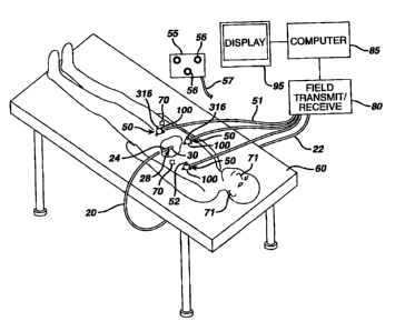
Fig. 1 is a perspective view of a preferred embodiment
of the present invention showing reference field
transducers attached to the body of the patient;
CA 02325540 2000-09-22
WO 99/49783 PCT/US99/06256
- 12 -
Fig. 2 is a diagrammatic sectional view depicting a
transducer assembly in accordance with one embodiment of
the invention;
Fig. 3 is a diagrammatic perspective view depicting
one element of the assembly utilized in Fig. 1;
Fig. 4 is a diagrammatic view of component shown in
Figs. 1-3;
Fig. 5 is an exploded, perspective view of a
reference field transducer and calibrating transducer
assembly in accordance with one embodiment of the
invention;
Fig. 6 is side perspective view of another preferred
embodiment of the present invention in which the reference
field transducers are independently movable;
Fig. 7 is a front view of another preferred
embodiment of the present invention in which the reference
field transducers are independently movable on a flexible,
sheet-like support;
Figs. 8a and 8b are layout and perspective views of
the three coil sensor of the present invention;
Figs. 9a and 9b are layout and perspective views of
an alternate embodiment three coil sensor;
CA 02325540 2000-09-22
WO 99/49783 PCT/US99/06256
- 13 -
Fig. 10 is a plan view of the three coil sensors of
the present invention, as arranged in relationship to each
other; and
Fig. 11 is a partial break away view of a three coil
sensor marked on a pad.
MODES FOR CARRYING OUT THE INVENTION
A system in accordance with one embodiment of the
invention is used in conjunction with an elongated probe
in the form of a tube or catheter 20 having a proximal end
22 and a distal end 24. A probe body 28 incorporating a
probe field transducer or position sensor 30 is physically
connected to the distal end 24 of catheter 20. Probe
field transducer 30 is preferably provided in the form of
a sensor arranged to detect magnetic or electromagnetic
fields. For example, the probe field transducer 30 may be
a multi-axis, solid-state position sensor of the type
disclosed in the aforementioned U.S. Patent 5,558,091.
Such a sensor incorporates a plurality of transducers
sensitive to magnetic field components in mutually
orthogonal directions. Other suitable position sensors
include coils as disclosed in the aforementioned U.S.
Patent 5,391,199 and in International Publication WO
96/05768. Such coils may be provided as a single coil or
as a plurality of orthogonal coils capable of detecting
field components in orthogonal directions.
CA 02325540 2000-09-22
WO 99/49783 PCT/US99/06256
- 14 -
Elongated probe or tube 20 is constructed and
arranged to be navigable within the body of the patient to
a desired location. For example, tube 20 may have the
structure of a conventional catheter, endoscope,
laparoscope or the like. The size and shape of tube 20
will also depend upon the region of the body to be
treated. The probe may incorporate essentially any device
which can be inserted or advanced into the body to perform
a medical procedure, such as for treatment, measurement or
observation, and capturing tissue samples or other
materials within the body. Tube 20 may also be
constructed to accommodate a conventional intrabody
medical instrument such a scissors or forceps, or other
surgical tools operable from the proximal end or handle of
the device. Such a surgical tool may be any conventional
surgical tool of the type commonly used in endoscopic,
arthroscopic or laparoscopic surgical procedures, or a
conventional biopsy sampling device. However, it should
be appreciated that essentially any instrument or device
which can be inserted into the body may function as a
probe, and hence the term "probe" should not be taken as
limited to any specific configuration.
The apparatus further includes a set of reference
assemblies 50, in this case three separate reference
assemblies, which are mounted directly on the patient in
desired, customizable positions. As best seen in Figs. 2
and 4, each reference transducer assembly 50 includes a
cylindrical coil 100 fabricated from fine gauge wire.
Such a coil preferably includes approximately 2000 turns
CA 02325540 2000-09-22
WO 99/49783 PCT/US99/06256
- 15 -
of wire to form a coil with a diameter of 3 or 4 inches or
less, and a height of 1-4 inch or less. Coils such as these
are currently sold as heater coils by Minco of
Minneapolis, Minnesota. Each cylindrical coil is formed
on a cylindrical bobbin 300 and defines a coil axis 302
concentric with the coil. Each reference assembly 50
further includes a housing incorporating a front panel 304
and a rear panel 306. These elements may be formed from
non-ferromagnetic materials such as polymers, non-
ferromagnetic metals and other materials conventionally
used in disposable medical devices. Front panel 304 is
provided with a cushioning layer 308 which in turn has an
adhesive coating on its exposed front surface 310. Front
panel 304 and hence its exposed, adhesive coated front
surface 310 extend generally transverse to the coil axis
302. A layer of a peelable release film 311 may be
removably positioned over surface 310. Layer 311 protects
the adhesive on surface 310 during shipment and handling,
but is removed during use of the assembly. In place of
adhesive layer 310, the reference assembly can be provided
with features such as elastic bands, straps, clamps or
other devices for securing it to the body of a patient.
Alternatively or additionally, the housing elements 304
and 306 can be provided with features such as holes or tie
points for cooperation with user-supplied fastening
devices such a sutures for holding the assembly in place.
In a further variant, the fastening features can be
provided directly on the reference field transducer or
coil 100, as on bobbin 300, and the housing elements can
be omitted.
CA 02325540 2000-09-22
WO 99/49783 PCT/US99/06256
- 16 -
Rear surface 306 is provided with vents 312 to permit
dissipation of heat generated during operation of coil
100. Other known features for promoting conduction and
dissipation of heat can be provided in the rear panel.
For example, the rear panel can be equipped with fins, and
can be fabricated from a highly heat conductive non-
magnetic material such as aluminum. Alternatively or
additionally, the region within the housing surrounding
coil 100 can be filled with a material having a high
specific heat or with a fusable material adapted to melt
and take up heat in latent heat of fusion, preferably at a
temperature slightly above normal body temperature such as
about 40-50 C. Other known devices for cooling an
electrical assembly can be provided as, for example, coils
for circulating a cooling medium such as water or air
within the assembly or to an external heat transfer device
can be provided. Thermoelectric cooling devices may also
be used. These heat dissipating and heat absorbing
features are intended to limit the temperature rise of the
front surface 310 of the front panel. As further
discussed below, the front panel will lie against the
patient during operation. Front panel 304, and cushioning
layer 308 may have substantial heat-insulating properties,
which also help to limit the temperature rise of front
surface 310.
A plurality of calibration transducer sockets 314 are
formed integrally with the housing at fixed positions
relative to coil 100. As best seen in Fig. 4, each
CA 02325540 2000-09-22
WO 99/49783 PCT/US99/06256
- 17 -
transducer assembly 50 has three sockets 314 disposed
around the periphery of coil 100. In the particular
configuration illustrated, the sockets are disposed
desirably at spaced locations around the coil axis 302 and
thus form vertices of a triangle in a plane perpendicular
to coil axis 302. Each socket 304 is adapted to receive a
calibration field transducer 316 and to hold the
calibration field transducer in a predetermined position
and orientation relative to the coil 100 of the same
reference assembly 50. As best seen in Fig. 3, each
calibration field transducer 316 desirably includes a set
of three orthogonal transducer elements 318, 320 and 322
adapted to detect magnetic field components in three
mutually orthogonal directions. The active transducer
elements may be solid state transducers such as Hall-
effect or magnetoresistive transducers. Alternatively,
the active elements may be coils wound on mutually
intersecting axes. The active elements 318, 320 and 322
are housed in an outer package or housing 324. Each
socket 314 and/or the housings 324 of the calibration
field transducers 316 and the sockets 314 may include
conventional features such as snaps, pins, clasps and
other features for mechanical fastening. Alternatively or
additionally, the housing 324 of the calibration
transducers may be adapted to fit closely within sockets
314, so that each housing is held in an accurate,
repeatable position with respect to coil 100. In yet
another alternative, the housings 324 of the calibration
transducers 316 can be formed integrally with the coil
housing elements 304 and 306, may be formed integrally
CA 02325540 2000-09-22
WO 99/49783 PCT/US99/06256
- 18 -
with the coil bobbin 300 or may be otherwise attached
permanently to the coil bobbin or housing.
The reference field transducers or coils 100, and the
calibration field transducers 316 of the various reference
assemblies 50 are connected through leads 51 to a field
transmitting and receiving device 80. Preferably,
reference assemblies 50 are removably detachable from
leads 51 to allow easy replacement and/or disposal after
use. Providing disposable reference assemblies is
advantageous since resterilization of the transducers,
which may cause damage to the sensitive transducers, can
be eliminated. In addition, providing detachable
transducers allows further customization by allowing
interchangeability among different sized reference
assemblies for different medical procedures and patient
sizes. As an alternative to leads 51, the various
transducers on each reference assembly can be connected to
the transmitting and receiving device 80 through wireless
telemetry, as by RF or infrared telemetry. In this case,
each reference assembly 50 may include a self-contained
power supply such as a battery.
Field transmitting and receiving device 80 is
connected to a computer 85, which can consist of a
microcomputer, work station, mainframe or other similar
computing device, which in turn is connected to a display
device, such as cathode ray tube (CRT) monitor 95. Field
transmitting and receiving device 80 and computer 85 are
arranged to cooperate with the probe field transducers 30
CA 02325540 2000-09-22
WO 99/49783 PCT/US99/06256
- 19 -
and coils reference field transducers 100 to transmit and
receive non-ionizing fields, preferably electromagnetic
fields, to determine the disposition of the probe 28 in
the frame of reference of the reference field transducers
100. As best seen in Figs. 1 and 4, reference assemblies
50 are mounted to the patient at arbitrary, user selected
dispositions by adhering the front surfaces 310 to the
patient. That is, the dispositions of the reference
assemblies 50, and hence the dispositions of the reference
field transducers 100 can be selected as desired by the
physician or other person mounting the reference
assemblies. Preferably, the reference assemblies are
mounted so as to place the various coils or reference
transducers 100 in proximity to a region of interest
within the patient, i.e., in proximity to a region where
the distal tip of probe 28 is to be employed. The
particular dispositions illustrated in Figs. 1 and 4 are
intended merely for purposes of illustration and should
not be taken as limiting the positions in which the
reference field transducers can be placed. For example,
the reference assemblies can be placed in a generally
coplanar arrangement on the patient's back, with the coil
axes 302 extending generally parallel to one another so
that the coil axes surround the center of the region of
interest. Alternatively, the various field transducers
can be placed in a generally U-shaped arrangement, as
depicted in Fig. 4, so that the axes 302 of the reference
transducers or coils 100 in all of the reference
assemblies converge in the region of interest.
CA 02325540 2000-09-22
WO 99/49783 PCT/US99/06256
- 20 -
When positioned on the patient, the reference field
transducers 100 define an external frame of reference.
Electromagnetic or magnetic fields can be transmitted
between reference field transducers 100 and the transducer
30 on the probe, such that the disposition of the probe
field transducer and probe 28 can be calculated from the
characteristics of the fields, such as strength and
direction, as detected by the probe field transducer.
Thus, the reference field-transducers 100 and the probe
field transducer 30 cooperatively define a plurality of
transmitter-receiver pairs. Each such pair includes one
transmitter and one receiver as elements of the pair. One
element of each such pair is disposed on the probe and the
other element of each such pair is disposed in the frame
of reference defined by the reference field transducers
100. Typically, at least one element of each transmitter-
receiver pair is disposed at a different position or
orientation than the corresponding element of the other
pairs. By detecting the characteristics of field
transmissions between the elements of the various pairs,
the system can deduce information relating to the
disposition of the probe in the external frame of
reference defined by the reference field transducers. The
disposition information can include the position of the
probe, the orientation of the probe, or both. However,
the calculation relies upon the reference field
transducers being positioned in known positions and
orientations relative to one another.
CA 02325540 2000-09-22
WO 99/49783 PGT/US99/06256
- 21 -
In the system of Figs. 1-4, because the reference
field transducers 100 may be placed at any desired
location and orientation relative to one another, it is
necessary to calculate their locations with respect to one
another. Calibration field transducers 316 cooperate with
reference field transducers or coils 100 to provide the
information necessary to calculate the position and
orientation of the reference assemblies relative to one
another. The coil 100 of each reference assembly 50
constitutes a single axis field transducer, whereas the
calibration field transducers 316 of each reference
assembly 50 represent a system of three three-axis
transducers disposed at known locations with respect to
one another. For example, the three calibration
transducers 316B, 316B2, and 316B3 of reference assembly
50B are at known locations relative to one another. As
described, for example, in International Patent
Publication WO 94/04938, the disclosure of which is
incorporated by reference herein, the position and
orientation of a single axis field transducer such as coil
100A can be fully deduced by actuating coil 100A to
produce a magnetic field and detecting the magnetic field
components in each of three mutually othrogonal directions
at each of the three calibration transducers 316B1, 316B2
and 316B3. The algorithm utilized in the aforementioned
94/04938 Publication is used therein for an entirely
different purpose, namely, location of a probe relative to
multiple reference transducers which are already in known
position relative to one another. Nonetheless, such
algorithm can be applied directly to the problem of
CA 02325540 2000-09-22
WO 99/49783 PCT/US99/06256
_ 22 _
finding the position and orientation of coil 100A with
respect to the calibration sensors on reference assembly
50B. In an initial stage, the algorithm proceeds> by
treating the reference field transducer coil 100A as if it
were a uniform radiator, and ignoring the effect of
orientation of coil 100A on the field component magnitudes
determined at calibration transducers 316B. Stated
another way, in this initial stage coil 100A is treated as
it is radiated a spherical field. Using this assumption,
and the field component magnitudes detected calibration
transducers 316B, the system arrives at an initial
estimate of the position of coil 100A relative to
reference assembly 50B. Using that initial estimate of
position and the detected field component magnitudes at
calibration transducers 316B, the system then calculates
orientation angles for coil 100A. Using the newly-
calculated orientation angles, the system calculates a
better estimate of position. The last two steps are
repeated until new estimate of position matches the last
previous estimate of position within a preselected
tolerance. Stated another way, the system converges to
the correct position and orientation angles. Further
details of the algorithm are given in the '938
Publication. The same algorithm can be used to find the
location of coil 100C with respect to reference assembly
50C. Likewise, by actuating coil 100B on reference
assembly 50B, the position and orientation of coil 100B
with respect to assembly 50C can be determined by
monitoring signals from the three, three-axis calibration
field transducers 316 on reference assembly 50C. The
CA 02325540 2000-09-22
WO 99/49783 PCT/US99/06256
- 23 -
location of coil 100B with respect to reference assembly
50A can be determined from the signals generated by
calibration field transducers 316A on reference assembly
50A while coil 100B is active. Similarly, when coil 100C
is activated, the disposition of coil 100C with respect to
assemblies 50A and 50B can be determined. The system
provides redundant information, including two
independently determined sets of position and orientation
parameters defining the relative dispositions of each pair
of reference assemblies. This redundant information can
be used in checking the values obtained and in arriving at
an estimate for the true values which minimized the total
error in the system. For example, by comparing the two
independently-determined values of relative disposition of
pair of assemblies, an estimate of the error for that pair
can be obtained. Similar estimates can be obtained for
the error in relative dispositions of other pairs of
reference assemblies. Using an iterative process, the
computer can select estimates of the true dispositions of
the various reference assemblies which yield the lowest
total error. Alternatively, the two estimates of relative
disposition for each pair of reference assemblies can
simply be averaged with one another.
In a further alternative arrangement, the system can
be modified to use fewer calibration transducers and
thereby eliminate some of the redundant information.
Thus, for the system as shown in Figs. 1-4 in which three
reference field transducers 100 are shown, there need not
be three calibration field transducers 316 on each
CA 02325540 2000-09-22
WO 99/49783 PCT/US99/06256
- 24 -
reference assembly in order to calibrate or determine the
relative positions of the reference field transducers with
respect to one another after they are placed. Namely,
there need only be enough transmitter-receiver pairs as
between the reference and calibration field transducers to
determine the locations of the reference assemblies with
respect to one another. For instance, in the system of
Figs. 1-4, where the reference field transducers comprise
single-axis field transmission coils, a system using only
three, three-dimensional field receiving calibration
transducers on only one reference assembly will allow
determination of the relative positions and orientations
of the three transmitting coils with respect to one
another. Alternatively or additionally, the reference
field transducers can function as calibration transducers.
For example, if coil 100A is energized with an alternating
current, the alternating field can be detected by
reference field transducers 100B and 100C of the other
reference assemblies. Those signals provide additional
information which can be used in the calibration process.
In another preferred embodiment, a fixed array of
calibration field transducers is provided, such as
calibration array 55 (Fig. 1) which includes a plurality
of calibration field transducers 56 attached to field
transmitting and receiving device 80 through leads 57.
Because the transducers 56 of the calibration array are
provided in fixed, known relationship with respect to one
another, the individual positions of each of the reference
field transducers with respect to the array transducers
CA 02325540 2000-09-22
WO 99/49783 PCT/US99/06256
_ 25 _
can be determined in accordance with the algorithms
disclosed, for example, in the aforementioned '938
International Publication. Once the positions of
reference field transducers 100 in the frame of reference
of calibration array 55 have been determined, the
dispositions of the reference field transducers relative
to one another can be calculated directly. In this
arrangement, the calibration field transducers can be
omitted from the reference assemblies 50.
Once the calibration of the reference field
transducers is completed, the disposition of the probe in
the external reference frame defined by the reference
field transducers can be determined as set forth for
instance in the 1091 patent, by transmitting and receiving
non-ionizing fields between the reference field
transducers and the probe field transducers.
In a method according to one embodiment of the
invention, the patient is positioned on the patient bed 60
and the reference assemblies 50 are independently
positioned in desired arrangements on or near the patient.
Next, the external frame of reference is determined by use
of the calibration and reference field transducer pairs.
Namely, the field transmitting and receiving unit 80 and
computer 85 actuate the reference field transducers or the
calibration field transducers to transmit and receive
fields as discussed above. Using the above described
method, the computer 85 calculates the disposition of the
CA 02325540 2000-09-22
WO 99/49783 PCT/US99/06256
_ 26 -
reference field transducers 100 with respect to one
another to determine the external reference frame.
Next, the distal end of the probe 28 is advanced into
the patient towards the area of interest, carrying the
probe field transducer 30. The field transmitting and
receiving unit 80 and computer 85 then actuate the
external field transducers 100 and probe field transducer
30 to transmit and receive fields. For example, where the
reference field transducers 100 are field transmitters,
the probe field transducers will send signals representing
the fields detected at the probe to the field transmit and
receive unit. Conversely, where the probe field
transducers are used as transmitters, drive signals are
sent to the probe field transducers. The computer 85 then
deduces the disposition of the probe field transducer 30
and thus deduces the disposition of the probe itself in
the external frame of reference defined by the reference
field transducers 100. As the dispositions of the
reference field transducers 100 relative to one another
are now known, the step of finding the disposition of the
probe field transducer 30 can be performed by known
techniques such as those taught in the '091 Patent and in
the '938 Publication.
In some procedures, it is desirable to display the
position of the probe on display 95 superposed on
previously-acquired images of the patient such as MRI, CT
or x-ray images. To do this, it is necessary to define a
patient reference frame and then translate the position of
CA 02325540 2000-09-22
WO 99/49783 PCT/US99/06256
- 27 -
the probe in the external frame of reference defined by
transducers 100 to the patient frame of reference. Stated
another way, the frame of reference of the reference
assemblies 50 and reference field transducers 100 must be
registered with the frame of reference of the image. This
can be accomplished in several ways. In one technique,
probe 28 and hence field transducer 30 are brought to
several prominent points on the patient which are readily
identifiable in the image as, for example, readily
identifiable bone structures depicted in the image data.
To facilitate this process, fiducial markers 71 can be
fastened in place on the patient's body before the image
is acquired, so that the fiducial markers are depicted in
the image and are accessible to the probe. The data
defining each prominent point or marker is supplied to the
computer, as by positioning a cursor over the depiction of
the point on display screen 95. When the physician brings
probe 28 into engagement with each prominent points or
fiducial markers, he supplies a manual input to the
computer, whereupon the computer records the current
position of probe 28 in the reference frame of the field
transducers 100 as the position of the prominent point or
marker in that reference frame. Data defining the
position of each such point or marker in the image frame
of reference is combined with data of defining the same
points in the frame of reference of field transducers 100
to arrive at a transposition vector relating the two
frames of reference to one another. Alternatively, the
contour of a rigid element in the patient's body as, for
example, the patient's face can be traced with the probe
CA 02325540 2000-09-22
WO 99/49783 PCTIUS99/06256
- 28 -
tip and matched to the same contour in the image frame of
reference. In another approach, one or more registration
marker field transducers 70 may be provided on fiducial
markers which are attached to the patient prior to
imaging. The system tracks disposition of the
registration field transducers in the frame of reference
of field transducers 100 in the same manner as it tracks
disposition of the probe transducer 30, so that positions
of the fiducial markers in the field transducer reference
frame are known.
One major advantage provided by embodiments of the
present invention where the reference field transducers
are mounted directly to the patient is that the
transducers define a reference frame that is fixed with
respect to with the patient. In many cases, such as where
the reference field transducers are mounted to rigid
portions of the patient's body (such as on the head) , the
requirement that the patient be rigidly fixed in a given
position to the patient bed is eliminated. This is
because it is no longer necessary to prevent relative
movement between the patient and the frame of reference
defined by the reference field transducers typically
mounted to the patient bed or attached to a wall or the
ceiling. For instance, if the reference field transducers
are mounted to the head, movement of the head of the
patient will not cause relative movement of the head with
respect to the reference field transducers since they are
positioned on the head. Stated another way, the frame of
reference defined by reference assemblies 50 and reference
CA 02325540 2000-09-22
WO 99/49783 PCT/US99/06256
_ 29
_
field transducers 100 is fixed to the patient and moves
along with the patient. There is no need to recalibrate
or reregister this frame of reference with respect to any
fixed frame of reference.
Where the reference transducers are not fixed
relative to one another as where the reference transducers
are mounted on flexible or movable portions of the
patient's anatomy, the system must recalibrate the
position of the reference assemblies relative to one
another. Such recalibration is performed by repeating the
calibration steps discussed above including operation of
the calibration field transducers and calculation of the
relative dispositions of the reference assemblies. The
recalibration can be performed periodically as, for
example, every few seconds during operation. More
preferably, recalibration is performed every time
disposition of the probe 28 is determined. Thus, the
system can operate cyclically. Each cycle includes a
calibration stage, in which the relative dispositions of
the reference assemblies and field transducers are
established, and a measurement stage, in which the
position and/or orientation of probe 28 is determined in
the frame of reference of the reference assemblies and
field transducers 100. They cycle may also include
recalibration of registration information as, for example,
location of one or more fiducial markers registration
transducers 70. Even where the reference assemblies are
mounted on a rigid portion of the body, periodic
CA 02325540 2000-09-22
WO 99/49783 PCT/US99/06256
- 30 -
recalibration is desirable as an assurance against
inadvertent movement of the reference assemblies.
In the embodiments described above, the various
transducers are time-multiplexed. For example, the
various reference field transducers are actuated at
different times during each calibration cycle. Other
multiplexing schemes, such as frequency-division and code
division multiplexing schemes, can be used as well. Also,
in the arrangements discussed above, all of the reference
field transducers are arranged to transmit magnetic
fields, whereas the calibration field transducers and
probe field transducer are arranged to detect such fields.
The reverse arrangement, where the probe and calibration
field transducers are transmitters and the reference field
transducers are detectors, can also be employed. In still
other possible arrangements, the calibration field
transducers include some transmitters and some detectors,
so that relative positions of the various reference
assemblies 50 can be determined by transmitting fields
between calibration transmitters on different transducer
assemblies. A mixed-mode arrangement, in which the
reference and probe transducers employ one type of field,
and the calibration transducers employ another type of
field, can also be used. For example, in a system using
magnetic or electromagnetic reference transducers, the
calibration field transducers may be acoustic or optical
transducers. Also, the various field transducers can have
more or fewer axes of sensitivity than those discussed
above. For example, the reference field transducers may
CA 02325540 2000-09-22
WO 99/49783 PCT/US99/06256
- 31 -
be multi-axis field transducers, whereas the probe field
transducer may be a single-axis filed transducer.
Particularly where the reference field transducers are
multi-axis field transducers such as multiaxis coils, the
reference field transducers can also serve as calibration
transducers. That is, the relative dispositions of the
reference assemblies can be deduced solely by detecting
signals transmitted between the reference field
transducers on different assemblies.
In yet another arrangement, the probe field
transducer, or another movable field transducer, is used
in place of the calibration transducers. During the
calibration step, the movable field transducer is inserted
successively in the various calibration probe sockets 314
of each field assembly while each reference coil is
actuated. For example, the probe tip 28 may be moved from
socket to socket. Provided that the probe sockets
position the movable transducer at known locations on each
reference assembly, and provided that the reference
assemblies do not move relative to one another during the
calibration step, this procedure yields the same
information as simultaneous acquisition of multiple
calibration probe signals in the embodiments described
above.
As shown in Fig. 5, a reference transducer assembly
may include a coil or reference transducer 100' mounted
between an upper or rear flexible layer 102 and a lower or
front flexible layer 104. Double-sided adhesive tape 106
CA 02325540 2000-09-22
WO 99/49783 PCT/US99/06256
- 32 -
may be affixed to the bottom surface of lower layer 104 so
that the entire coil assembly can be readily attached to
the patient. One or more reference transducers 52 can be
mounted on such an assembly, as on the upper layer 102.
In the embodiments discussed above, the reference
transducers are mounted on the patient. However, the
independently-positionable reference transducers also can
be mounted at other locations near the patient. Turning
now to Fig. 6, a further embodiment of the present
invention is provided where the reference field
transducers are attached to common structure yet are still
independently movable with respect to one another. Here,
a common support arm 200 is provided to which is attached
a number of flexible, goose neck arms 205 to which
reference field transducers 210 are attached. An
adjustable mounting mechanism 215 is provided for
attachment of the coil carrying structure to the patient
bed or other desirable location. The relative positions
of the field transducers with respect to one another may
be determined after they are positioned as described
above. It should be appreciated that there are a number
of other effective ways to attach the reference field
transducers to a common support structure to allow
independent movement of the transducers, such as by using
bendable wire arms, arms with adjustable linkage
mechanisms or other such adjustable frames.
A yet further embodiment of the present invention is
shown in Fig. 7, in which a single sheet-like support 220
CA 02325540 2000-09-22
WO 99/49783 PCTIUS99/06256
- 33 -
is provided to which reference field transducers 225 are
attached. In this embodiment, the sheet can be positioned
over or under the patient and each of the transducers -can
be moved to a desired location by gathering excess
material of the sheet. Alternatively, the flexible sheet
can be formed of a stiff, yet sufficiently flexible
material so as to allow the sheet to be bent into any
desired positions to allow adjustment of the positions of
the field transducers.
The coil or transducer arrangements of the present
invention solve a number of problems associated with
fixed, non-movable coil systems. For instance, non-
movable coil systems can interfere with the access of the
surgeon. Non-movable coil systems generally cannot be
positioned above the patient as they would block the
lighting, and may not be positionable under the patient
where a metal be would cause interference and not all beds
can be replaced or retrofitted to eliminate this problem.
Moreover, with non-movable coils, high accuracy mapping
volumes are too small to be useful if the coils cannot be
moved from moment to moment.
The present invention solves these problems since the
reference field transducers can be positioned in a least
obtrusive manner and can even be moved out of the way or
to a new locale during the procedure. Moreover, the
transducers can be moved closer to area of interest to
provide better concentration of fields and better
readings. The present invention further allows the use of
CA 02325540 2007-03-06
- 34 -
even smaller reference transducers since there is no
longer a need to provide large coils to generate fields
over a large area to ensure broad coverage. In preferred
embodiments, the transducers can be disposable allowing
easy replacement of damaged or contaminated transducers
and the use of different size and types of transducers for
different applications. A kit of such reference field
transducers, with or without the calibration field
transducers, can also be provided for the physician and
may contain identical transducers or transducers of
different sizes for different applications.
The present invention can also be used in conjunction
with the system disclosed in U.S. Patent No. 5,729,129.
In the 1380 application, feedback is used
to adjust the currents supplied to the reference field
transducers or coils to ensure that the sensor on the
probe receive fields within a preselected range of
magnitudes regardless of the location of the probe. This
ensures that the sensor operates within its optimal range
and allows the use of compact transmitters and sensors.
Thus, the feedback techniques disclosed in the '380
application can be used wi-th the present invention to
adjust the strengths of the non-ionizing fields generated
by the reference field transducers and/or the probe field
transducer.
The present invention may further be used in
conjunction with the multiple probe system disclosed in
CA 02325540 2007-03-06
- 35 -
PCT Publication No. WO 97/029709 which is commonly
assigned to the assignee of the present application.
In preferred embodiments of this
system, a medical probe such as a catheter is guided
within the body of a patient by determining the relative
dispositions of the probe relative to another probe, as by
transmitting non-ionizing radiation to or from field
transducers mounted on both probes. In particular, a site
probe may be secured to a lesion within the body, and an
instrument probe for treating the lesion may be guided to
the lesion by monitoring relative positions of the probes.
In many embodiments of this system, it is not necessary to
register the positions of the probes with image data, or
to superpose probe locations on images. The independently
movable reference field transducer arrangements of the
present invention can therefore be used with the site
probe/instrument probe system, with or without
simultaneous patient imaging-; to locate the dispositions
of the probes in the frame of reference defined by the
reference field transducers. So long as the dispositions
of both probes are found in the same frame of reference,
the relative disposition of the two probes can be
determined. For example, the relative dispositions can be
determined properly even if the reference field
CA 02325540 2000-09-22
WO 99/49783 PCT/US99/06256
- 36 -
transducers move relative to one another (as where the
field transducers are mounted on soft tissue), provided
that the system is recalibrated to update the dispositions
of the field transducers relative to one another during
each cycle or whenever movement occurs. In a further
variant, where the reference field transducers are mounted
on parts of the body subject to repetitive natural
movement, such as on the chest or other area which moves
repetitively in the respiratory cycle, the system can be
calibrated at a particular point in the natural movement
cycle (e.g., end inspiration or end expiration) and can be
actuated to determine the location of a probe at the same
point in the natural movement cycle. Such a system can
also be used where superposition of the probe
representation on a previously-acquired image is desired
as, for example, where the image is an image acquired at
the same point of the natural movement cycle.
Superior signal-to-noise ratio performance is also
achieved with the independently positionable reference
field transducers of the present invention. In general,
with the use one or more reference field transducers in a
probe locating system, there is a region of volume
associated with the field transducers in which the signal-
to-noise ratio of the assembly is optimized (a so-called
"optimal region"), where high-accuracy field measurements
can be made by a probe transducer. With prior probe
location systems in which the reference transducers are
mounted in fixed positions about the patient bed, however,
this optimal region will typically encompass a large area
CA 02325540 2000-09-22
WO 99/49783 PCT/US99/06256
- 37 -
to account for all possible areas of interest. For
example, a system using bed-mounted transducers may be
required to locate the probe in the thorax of one patient
and in the head of another patient. The larger the
optimal regions, however, the more difficult it is to
achieve a high signal-to-noise ratio throughout such
region. With the independently positionable transducer
assemblies of the present invention, this optimal area can
be made smaller and highly concentrated. For each
procedure, the optimal area can be configured to match the
region where the probe is to be tracked. Accordingly,
preferred embodiments of the present invention can provide
enhanced signal-to-noise performance in comparison to a
fixed transducer assembly using the same transducers in a
large fixed array. The signal-to-noise performance of the
system also depends on the properties of the probe
transducer. The enhanced performance provided by
preferred embodiments of the present invention can provide
acceptable signal-to-noise performance with a less
sensitive probe transducer, which in turn facilitates
miniaturization of the probe transducer and probe.
Alternatively, the benefit provided by the movable
transducer assembly can permit use of smaller, cheaper and
less obtrusive reference transducers while maintaining
satisfactory performance. Moreover, the reference field
transducers can be positioned to provide optimum
performance in that region without obstructing the
physician's access to the patient. Merely by way of
example, where the surgeon will operate through a
CA 02325540 2000-09-22
WO 99/49783 PCT/US99/06256
- 38 -
craniotomy on the left side of the head, the reference
assemblies can be placed on the back, top and right side
of the head.
Yet another advantage of the embodiments disclosed
herein is the ability to provide adjustment of the
reference field transducers if they are moved or if the
initial positioning of the reference field transducers
yields poor readings. Thus, the surgeon can relocate the
reference assemblies, or even add additional reference
assemblies, during a procedure.
It will be further appreciated that although aspects
of the above preferred embodiments have been described
with reference to a system for position determination
based on magnetic fields, the present invention is equally
applicable to other types of position determination
systems known in the art, such as systems that use other
forms of field transducers, such as those which radiate
and detect electromagnetic, magnetic, acoustic, optical
ultrasonic or other non-ionizing fields.
The method of using calibration field transducers for
calibrating the relative positions of the reference
transducers with respect to one another in accordance with
the present invention can also be used to replace or
augment the manner of determining the relative positions
of the linked reference field transducers. Namely,
instead of including a rotation measuring device, such as
an optical encoder device, which allows the angle between
CA 02325540 2000-09-22
WO 99/49783 PCT/US99/06256
- 39 -
transducer-carrying arms to be accurately determined so
that the relative positions of reference field transducers
are known, calibration field transducers can be used as
disclosed herein.
The coil sensors according to the present invention
are especially adapted for use as the calibration field
transducers and described in Figures 1-4, although the
present invention can be used in other applications in
which one desires to measure components of magnetic
fields. Referring to Figure 8a of the present
application, in one preferred embodiment of the present
invention, a three-axis coil sensor is formed by
providing three separate calibration coils 12, 14 and 16
on a single, solitary planar base panel 10. Base panel
10 can be formed from non-ferromagnetic materials such
as polymers, non-ferromagnetic metals and other
materials conventionally used in disposable medical
devices. Preferably, the base panel is formed from a
polyimide.
In forming the sensor of the present
invention, the base panel 2 is initially provided in a
flat, planar configuration as shown in Fig. 8a.
Calibration coils 4, 6, and 8 are then affixed to
subpanels 13, 15 and 17 which in turn comprise base
panel 2. The calibration coils are preferably
constructed by winding fine gauge wire around a bobbin,
removing the bobbin and laminating the remaining wire
coil directly onto the base panel. Alternately, the
CA 02325540 2000-09-22
WO 99/49783 PCT/US99/06256
- 40 -
bobbin can be left in place and affixed to the base
panel with the coil. Once the coils are located and
affixed to the subpanels, the subpanels are then folded
along fold lines 17 and 18 to form the three-axis coil
sensor such that all three coils are disposed orthogonal
to one another along the x, y and z axes as shown in
Fig. 7b. Each calibration field transducer is therefore
adapted to detect magnetic field components in three
mutually orthogonal directions.
In another embodiment of the present invention
as shown in Fig. 9a, coils 22, 24 and 26 are formed on
subpanels 21, 23 and 25 forming base panel 20. With
this arrangement, the folding of the panel 20 along fold
lines 27 and 28 again produces a 3-axis coil assembly
where the three coils are mutually orthogonal to one
another but with one of the coils being offset by a
small distance from the other two coils, as shown in
Fig. 8b.
In the embodiment shown in Figure 10, the
present invention incorporates three, three-axis coil
sensors 30, 31, 32 attached to the outer periphery 33 of
a main planar substrate 36. A main coil 35 is provided
on a main planar substrate 36. The main coil can be
used like reference field transducer 100 described in
the embodiment of Figs. 1-4. Preferably, each base
panel carrying each 3-axis sensor and the planar
substrate 36 are formed as one single substrate, and
appropriate fold lines are provided in the base panels
CA 02325540 2000-09-22
WO 99/49783 PCT/US99/06256
- 41 -
and at the edge where the base panels attach to the
outer periphery of the main planar substrate 36 to allow
the calibration coils. to be folded such that they are
disposed orthogonal to one another along their x, y and
z axes. Preferably, each 3-axis sensor is positioned
approximately 120 degrees apart from another spaced
about the main coil 35.
Main coil 35 is preferably fabricated from
approximately 800 to 1600 turns and preferably 1550
turns of 27 gauge wire or less to form coil with a
diameter of 3 inches or less, and preferably 2.32
inches. Each individual calibration coil of each three-
coil sensor 30, 31, 32 is preferably fabricated from
approximately 1400 to 2200 turns, and preferably 2000
turns of 46 gauge wire to form a coil with an outside
diameter of 0.5 inches or less, and preferably 0.32
inches. Alternately, the coils can be formed by other
techniques such as printing the coils directly on the
substrates. Lead wires (not shown) are provided to
connect the coils to the appropriate electronics such as
driver and amplifiers. The leads can constitute
external wires, conductors within the substrates of
conductors printed on the surface of the substrates.
The reference transducer assembly of Fig. 10,
which includes main coil 35 as well as calibration coils
30, 31, 32 attached to the same panel as the main coil,
can replace the entire reference transducer assembly 50
of the embodiment described in Figs. 1-4.
CA 02325540 2000-09-22
WO 99/49783 PCT/US99/06256
- 42 -
Yet another embodiment of the present
invention is depicted in Fig. 11, which is a fragmented
view of a portion of a main coil and shows the placement
of a 3-axis coil on a portion of the substrate carrying
the main coil. Namely, in this embodiment, the 3-axis
coil assembly 40 is assembled in a manner similar to the
assembly of the 3-axis coil sensor assembly shown in
Figs. 8a and 8b. However, in this case, the three coil
assembly is adapted to be inserted into recesses 41 and
42 provided on a main planar substrate 46. Recess 41 is
adapted to accept any slightly protruding portions of
coils 50 and 51 while recess 42 is formed to accept the
outward protrusion of coil 52. Again, main coil 45 is
formed on the same substrate in which recesses 42 and 41
are formed; namely, substrate 46.
As discussed above, the coil assemblies of the
present invention are particularly adapted to be used in
connection with the individually positionable transducer
assemblies disclosed in the earlier embodiments. For
example, the coil sensor assemblies of Figs. 7b and 8b
can be used as the calibration field transducers 316 and
positioned within calibration transducer sockets 314 of
Figs. 1-4.
As these and other variations and combinations of the
features described above can be utilized without departing
from the present invention, the foregoing description of
the preferred embodiments should be taken by way of
CA 02325540 2000-09-22
WO 99/49783 PCT/US99/06256
- 43 -
illustration rather than by way of limitation of the
invention as defined by the claims.