Note: Descriptions are shown in the official language in which they were submitted.
CA 02335910 2003-08-22
WO 99167302 PCfIUS99/13881
TUBULAR INJECTOR WITH SNL)BBING JACK AND OSCILLATOR
Bacrground of the Invention
E'i,g:~d of the Invention
This invention relates to the running and freeing of
stuck or jammed tubulars downhole without the use of
overhead tubular and oscillator support structure, using
eccentric weight mechanical oscillators. More particularly,
the invention includes a snubbing-type jack and an
oscillator apparatus having a central tubular stem for
accommodating tubulars and designed to utilize resonant
frequency vibration in combination with the snubbing-type
jack for freeing tubulars such as drill pipe, casing and
other jointed tubulars, as well as continuous or coiled
tubing in the well. freeing of the coiled tub9.ng or other
tubulars in the well by typically resonance vibration is
effected when the coiled tubing or alternative tubular has
been clamped to the oscillator and isolated from the jack.
~In a first embodiment the osci.llator/snubbing jack
combination operates to run jointed tubulars in a well and
free stuck downhole members by selectively transferring the
tubular load from the snubbing jack to the oscillator and
operating the oscillator to vibrate and free the tubular
-1-
CA 02335910 2000-12-21
WO 99/67502 PCT/US99/13881
load in the well. In a second embodiment the apparatus is
modified to run coiled tubing from a reel by adding a
"gooseneck" coiled tubing guide and a coiled tubing injector
- and for guiding the coiled tubing through a central stem of
the oscillator and through the injector, into and from the
well.
Oil field tubulars such as well liners, casing, tubing
and drill pipe which become stuck in a well bore due to
various downhole conditions have been one of the principal
sources of problems for oil operators and have expanded the
business activity of fishing service companies in this
century. During this period of time, many new and
innovative tools and procedures have been developed to
improve the success and efficiency of fishing operations.
Apparatus such as electric line free point tools, string
shot assisted backoff, downhole jarring tools, hydraulic-
actuated tools of various types and various other tools and
equipment have been developed for the purpose of freeing
stuck or jammed tubulars downhole in a well. Although use
of this equipment has become more efficient with~time, the
escalation in cost of drilling and workover operations has
resulted in a proliferation of stuck pipe, liners, casing,
and like tubulars downhole, frequently leading to well
abandonment as the most expedient resolution of the problem.
The use of vibration, and resonant vibration in
particular, as a means of freeing stuck tubulars in a well
bore has the potential to be immediately effective and thus
greatly and drastically reduce the cost involved in tubular
recovery operations. Resonance occurs in vibration when the
-2-
CA 02335910 2000-12-21
WO 99/67502 PCT/US99/13881
frequency of the excitation force is equal to the natural
frequency~of the system. When this happens, the amplitude
(or stroke) of vibration will increase without bound and is
governed only by the degree of damping present in the
system.
A resonant vibrating system will store a significant
quantity of energy, much like a flywheel and the ratio of
the energy stored to the energy dissipated per cycle is
referred to as the systems "Q". A high energy level allows
the system to transfer energy to a given load at an
increased rate, much like an increase in voltage will allow
a flashlight to burn brighter with a given bulb. Only
resonant systems will achieve this energy buildup and
exhibit the corresponding efficient energy transmission
characteristics which assure large energy delivery and
corresponding force application to a stuck region of pipe or
tubing.
Under resonant conditions, a string of pipe or tubing
will transmit power over its length to a load at the
opposite end, with the only loss being that necessary to
overcome resistance in the form of damping or friction. In
effect, power is transmitted in the same manner as the
drilling process transmits rotary power to a bit, the
difference being that the motion is axial translation
instead of rotation. The load accepts the transmitted power
as a large force acting through a small distance. Resonant
vibration of pipe or tubing can deliver substantially higher
sustained energy levels to a stuck tubular than any
conventional method, including jarring. This achievement is
-3-
CA 02335910 2000-12-21
WO 99/67502 PCT/US99/13881
due to the elimination of the need to accelerate or
physically move the mass of the pipe or tubing string.
Under resonant conditions, the power is applied to a
vibrating string of pipe or tubing in phase with the natural
movement of the pipe or tubing string.
When an elastic body is subjected to axial strain, as
in the stretching of a length of pipe, the diameter of the
body will contract. Similarly, when the length of pipe or
tubing is compressed, its diameter will expand. Since a
length of pipe or tubing undergoing vibration experiences
alternate tensile and compressive forces as waves along the
longitudinal axis (and therefore longitudinal strains), the
pipe or tubing diameter will expand and contract in unison
with the applied tensile and compressive waves. This means
that for alternate moments during a vibration cycle the pipe
or tubing may actually be physically free of its bond.
The term "fluidization" is used to describe the action
of granular particles when excited by a vibrational source
of proper frequency. Under this condition, granular
material is transformed into a fluidic state that offers
little resistance to movement of body through the media. In
effect, it takes some of the characteristics and properties
of a liquid. Accordingly, skin friction, the force that
confines a stuck tubular, is reduced to a small fraction of
its normal value due to any unconsolidated media that may
surround the tubular, tending to become fluid at the
interface with the vibrating pipe. Accordingly, the
vibrational energy received at the stuck area works to
effect the release of a stuck tubular member through the
-4-
CA 02335910 2000-12-21
WO 99/67502 PCT/US99/13881
application of large percussive forces, fluidization of
granular material, dilation and contraction of the pipe or
tubing body and a reduction of well bore friction or hole
drag.
Snubbing units, coiled tubing units, jacks or casing
jacks are typically used in well construction, completion
and remedial or workover situations where there is no
overhead tubular support structure, and where objects such
as various tubulars may be stuck in the well bore and must
be removed in order to complete the work. Additionally, the
pipe work string or tubing itself may become stuck in the
well bore and must be freed and recovered so that the work
can continue. In either event, pipe or tubing vibration
from the surface may be used as a method of recovering the
stuck tubular members or the work string itself and for
reducing tubular insertion and removal friction, as well as
other useful purposes.
A typically resonant vibration system used in
connection with snubbing-type jacks and units in oilfield
tubular running and extraction applications according to
this invention, consists of a mechanical oscillator mounted
by means of vibration insulators, isolators or reflectors on
a snubbing-type unit or jack. Under circumstances where the
tubular in the well is coiled tubing, a coiled tubing
injector and a "gooseneck" coiled tubing guide are added to
this combination. The oscillator generates an axial
sinusoidal force that can be tuned to a given frequency
within a specified operating range when the tubular is
clamped or otherwise secured to the oscillator and is thus
-5-
CA 02335910 2000-12-21
WO 99/67502 PCT/US99/13881
isolated from the snubbing-type jack when the tubular is
released by the jack or tubing injector and suspended by the
operator. The axial force generated by the oscillator acts
- on the tubular extending through the snubbing unit or coiled
tubing injector and secured to the oscillator, to create
axial vibration of the tubular. When tuned to a resonant
frequency of the system, energy developed at the oscillator
is efficiently transmitted to the stuck member, with the
only losses being those attributed to frictional resistance.
The effect of the system reactance is eliminated because
mass inductance is equal to spring capacitance at the
resonant frequency. The total resonant system is designed
such that the components act in concert with one another,
thus providing an efficient and effective extraction system.
The principal of resonant axial vibration of pipe and
other threaded tubulars can therefore be applied to coiled
tubing, as well as threaded tubulars such as casing and
drill pipe, using a snubbing-type or load-bearing unit of
substantially any design for running the coiled tubing in
and out of a well. The combination of a mechanical
oscillator and a snubbing-type jack, along with a
"gooseneck" tubing guide and a coiled tubing injector is
highly effective to "run" the tubing and to remove stuck
coiled tubing from a well, as well as maintaining and
enabling good well control, along with the facility for
circulating fluids through the coiled tubing into and from
the well.
-6-
CA 02335910 2000-12-21
WO 99/67502 PCT/US99/1388I
Various pipe recovery techniques are well known in the
art. An 'early pipe recovery device is detailed in U.S.
Patent No. 2,340,959, dated February 8, 1944, to P.E. Harth.
The Harth device is characterized by a suitable electrical
or mechanical vibrator which is inserted into the pipe to be
removed, such that the vibrator may be activated to loosen
the pipe downhole in the well and enable removal of the
pipe. A well pipe vibrating apparatus is detailed in U.S.
Patent No. 2,641,927, dated June 16, 1953, to D. B. Grabel,
et al. The device includes a vibrating element and a motor-
powered drive which is inserted in a well pipe to be
loosened and removed, to effect vibration of the pipe and
subsequent extraction of the pipe from the well. U.S.
Patent No. 2,730,176, dated January 10, 1956, to W. K. J.
Herbold, details a means for loosening pipes in underground
borings. The apparatus includes a device arranged within a
paramagnetic cylindrical body, including a drill, a rod
rotatably mounted within the body and a disc member secured
to one end of the drill rod, the disc member having a mass
which is substantially equally distributed around the axis
of the drill rod to define a surface of revolution. A motor
is provided for rotating the drill rod and a magnetic
apparatus for forcing the disc member into physical contact
with the inner walls of the body and into rolling contact
with the inner surface of the pipe upon rotation of the
drill rod, to loosen the pipe downhole. U.S. Patent No.
2,972,380, dated February 21, 1961, to A. G. Bodine, Jr.,
details an acoustic method and apparatus for moving objects
held tightly within a surrounding medium. The device
_7_
CA 02335910 2000-12-21
WO 99/67502 PCT/US99/13881
includes a vibratory output member of an acoustic wave
generator 'attached to an acoustically-free portion of the
stuck tubular. The method includes operating the generator
- at a resonant frequency to establish a velocity node
adjacent to the stuck point and a velocity antinode at the
coupling point adjacent to the generator, to loosen the
stuck member from the well. U.S. Patent No. 3,189,106,
dated June 15, 1965, to A. G. Bodine, Jr., details a sonic
pile driver which utilizes a mechanical oscillator and a
pile coupling device for coupling the oscillator body to a
pile and applying vibrations of the pile to drive the pile
into the ground. U.S. Patent No. 3,500,908, dated March 17,
1970, to D. S. Barter, details apparatus and method for
freeing well pipe. The device includes a number of
rotatable, power-driven eccentrics which are connected to an
elongated member such as a drill pipe that is stuck in an
oil well bore hole and to a resiliently-movable support
suspended from the traveling block of an oil derrick. When
the power-driven eccentrics are operated, the elongated
member is subjected to vertically-directed forces that free
it from the stuck position. U.S. Patent No. 4,429,743,
dated February 7, 1984, to Albert G. Bodine, details a well
servicing system employing sonic energy transmitted down the
pipe string. The sonic energy is generated by an orbiting
mass oscillator coupled to a central stem, to which the
piston of a cylinder-piston assembly is connected. The
cylinder is suspended from a suitable overhead suspension
device such as a derrick, with the pipe string being
suspended from the piston in an in-line relationship. The
-8-
CA 02335910 2000-12-21
WO 99/67502 PCT/US99/13881
fluid in the cylinder affords compliant loading for the
piston, while the fluid provides sufficiently high pressure
to handle the load of the pipe string and any pulling force
- thereon. The sonic energy is coupled to the pipe string in
the longitudinal vibration mode, which tends to maintain
this energy along the string. U.S. Patent No. 4,574,888
dated March 11, 1986, to Wayne E. Vogen, details a "Method
and Apparatus For Removing Stuck Portions of A Drill
String". The lower end of an elastic steel column is
attached to the upper end of the stuck element and the upper
end of the column extends above the top of the well and is
attached to a reaction mass lying vertically above, through
an accelerometer and vertically-mounted compression springs
positioned in parallel with a vertically-mounted, servo-
controlled, hydraulic cylinder-piston assembly. Vertical
vibration is applied to the upper end of the column to
remove the stuck element from the well. A "Device For
Facilitating the Release of Stuck Drill Collars" is detailed
in U.S. Patent No. 4,576,229, dated March 18, 1986, to
Robert L. Brown. The device includes a first member mounted
with the drill pipe disposed in a first position and a
second member concentrically mounted with a drill collar or
drill pipes in a second position below the first position.
Rotation of the drill string from the surface causes a
caroming action and vibration in a specified operative
position of the device, which helps to free stuck portions
of the drill pipe. U.S. Patent No. 4,788,467, dated November
29, 1988, to E.D. Plambeck details a downhole oil well
vibrating apparatus that uses a transducer assembly spring
_g_
CA 02335910 2003-08-22
chamber piston and spring to effect vibration of downhole
tubulars. U.S. Patent No. 5,234,056, dated August 10, 1993, to
Albert G. Bodine, details a "Sonic Method and Apparatus For
Freeing A Stuck Drill String". The device includes a mechanical
oscillator employing unbalanced rotors coupled to the top end
of a drill string stuck in a bore hole. Operation of the
unbalanced rotors at a selected frequency provides resonant
vibration of the drill string to effect a reflected wave at the
stuck point, resulting in an increased cyclic force at this
point. Patents detailing jacking devices and coiled tubing and
other tubular insertion and removal devices, include U.S.
4,465,131, dated August 14, 1984, to Boyadjieff, et al; U.S.
4,585,061, dated April 29, 1986, to Lyons, et al; U.S.
4,655,291, dated April 7, 1987, to Cox; and U.S. 5,566,764,
dated October 22, 1996, to Elliston.
The prior art is well established regarding the
application of vibration to stuck downhole tubulars of the
conventional type (threaded pipe). However, there is no known
technique or suggestion of any means or method for handling
continuous pipe or tubing such as coiled tubing, in addition to
threaded tubulars, using a mechanical oscillator mounted on a
snubbing-type jack or lifting mechanism, in a vibrational
application. Therefore, the present invention provides an
apparatus for working and freeing coiled tubing or other stuck
pipe or equipment in a well without using overhead support
structure, wherein the tubing or pipe may be vibrated in the
well bore by an oscillator mounted on a support structure in
vibration-insulated relationship, which support structure
includes a tubing or pipe-lifting and lowering apparatus.
This invention also provides a new and improved coiled
tubing and threaded tubular running and recovery apparatus,
including an oscillator having a hollow central stem for
receiving the tubular and a snubbing jack in the case of the
threaded tubulars, and including a snubbing-type jack or
lifting mechanism, a coiled tubing guide and a coiled tubing
injector where coiled tubing is used, which apparatus
-10-
i
CA 02335910 2003-08-22
facilitates running, releasing and recovering by vibration, the
tubulars and other objects stuck or jammed downhole in a well.
This invention also provides a new and improved tubing
injector with snubbing-type jack or lifting mechanism and
oscillator apparatus, which combines a mechanical oscillator
having a hollow central stem or tube and clamps for receiving
coiled tubing, a coiled tubing guide for guiding the coiled
tubing from a reel to the oscillator, a coiled tubing injector
for receiving the tubing from the oscillator and running the
tubing in a well and a snubbing-type jack for raising and
lowering the oscillator, which oscillator is selectively
clamped to the coiled tubing and generates a resonant vibration
to facilitate the release of stuck or jammed coiled tubing in
the well.
The invention also provides a new and improved coiled
tubing oscillating/snubbing-type jack or lifting apparatus,
including a coiled tubing guide and injector, that may be
applied to a continuous length of coiled tubing without cutting
the tubing and operated to run, isolate and vibrate the coiled
tubing and remove the coiled tubing from a stuck or jammed
position in a well.
This invention also provides a new and improved coiled
tubing oscillating/snubbing-type jack apparatus for running and
freeing tubulars in a well, which apparatus is characterized by
a mechanical oscillator, a snubbing-type jack or lifting device
located above an injector head seated on the wellhead or other
well structure and a coiled tubing guide or 'gooseneck"
positioned above the oscillator and adapted to receive a length
of coiled tubing from a reel and direct the coiled tubing
through a hollow central stem and a pair of clamps in the
oscillator and through the coiled tubing injector head, into
and from the well, wherein the oscillator is typically mounted
on the snubbing-type jack in vibration-insulated and isolated
relationship to facilitate selectively clamping the coiled
tubing to the oscillator and thus isolating and vibrating the
-11-
I ri l
CA 02335910 2003-08-22
coiled tubing and removing the coiled tubing from a stuck or
jammed condition in the well.
In another aspect, the present invention provides a
tubing injector with snubbing-type jack and oscillator
apparatus which utilizes a mechanical oscillator mounted on a
snubbing-type jack by means of vibration-isolating members and
receiving a length of coiled tubing from a reel through a
tubing guide for feeding to the coiled tubing injector and
isolating the coiled tubing using clamps, applying a resonant
vibration directly to the coiled tubing and raising and/or
lowering the oscillator by operation of its jack, thus removing
the coiled tubing from a stuck or jammed condition in a well.
The present invention also provides an
oscillator/snubbing-type jack apparatus and method of operation
which oscillator is mounted on the snubbing-type jack by means
of typically rubber or spring vibration insulators, isolators
or reflectors and operates to run threaded tubulars in a well
and to release stuck tubulars by vibration. In the case of
coiled tubing, the oscillator/snubbing jack combination
includes a coiled tubing guide, or "gooseneck" and a coiled
tubing injector for receiving a length of coiled tubing
extending from a coiled tubing reel and directing the coiled
tubing through a hollow bore or channel and a pair of clamps in
the oscillator and the coiled tubing injector head, into the
well, such that the apparatus can be operated to clamp the
coiled tubing, vibrationally isolate and insulate the coiled
tubing from the snubbing-type jack and vibrate the coiled
tubing, typically at a resonant frequency, and operate the jack
apparatus to remove the coiled tubing from a stuck or jammed
condition in the well.
The present invention also provides a method of freeing
stuck tubulars, including threaded tubulars such as drill pipe
and the like, as well as coiled tubing, in a well using an
oscillator and snubbing-type jack running and recovery
apparatus, which method includes extending the threaded tubular
through a pair of clamps and a tubular stern in the oscillator
-12-
j
CA 02335910 2003-08-22
and through the snubbing jack, clamping the tubular in the
oscillator, releasing the tubular from the snubbing jack and
vibrating the tubular. When coiled tubing is run, the method
includes installing a coiled tubing guide above the oscillator
for guiding the coiled tubing from a reel through the
oscillator, placing a coiled tubing injector beneath the
oscillator over the wellhead or structure for receiving and
conventionally running the coiled tubing, clamping the coiled
tubing in the oscillator and vibrating the coiled tubing to
reduce the friction of tubing insertion and extraction in a
well while operating the jack.
Summary of the Invention
These and other features of the invention are provided in
a new and improved oscillator and snubbing-type jack tubular
recovery apparatus and method of operation.
Accordingly, the present invention provides a tubular
injector apparatus for inserting a jointed tubular into a well
bore of an oil or gas well and lifting the tubular from the
well bore, said tubular injector apparatus comprising a
snubbing jack for selectively inserting the tubular into the
well bore and lifting the tubular from the well bore and an
oscillator provided on said snubbing jack for selectively
engaging the tubular and vibrating the tubular in the well
bore.
Accordingly, the present invention provides a tubular
injector apparatus for inserting a jointed tubular into a well
bore of an oil or gas well and lifting the tubular from the
well bore, said tubular injector comprising a snubbing jack for
selectively inserting the tubular into the well bore and
lifting the tubular from the well bore; a base plate carried by
said snubbing jack; a plurality of vibration isolators or
reflectors upward-standing from said base plate, and an
oscillator provided on said vibration reflectors for
selectively engaging the tubular and vibrating the tubular in
the well bore.
-13-
i I
CA 02335910 2003-08-22
Accordingly, the present invention provides a coiled
tubing injector apparatus for inserting coiled tubing into a
well bore of an oil or gas well and lifting the coiled tubing
from the well bore, said coiled tubing injector apparatus
comprising a coiled tubing injector for selectively inserting
the coiled tubing into the well bore and lifting the coiled
tubing from the well bore; a mount frame positioned over said
coiled tubing injector; an oscillator supported on said mount
frame for selectively engaging the coiled tubing and vibrating
the coiled tubing in the well bore; and a coiled tubing guide
disposed above said coiled tubing injector for feeding the
coiled tubing through the oscillator and into the coiled tubing
injector.
Accordingly, the present invention provides a coiled
tubing injector apparatus for inserting a coiled tubing into a
well bore of an oil or gas well, lifting the coiled tubing from
the well bore and freeing coiled tubing in the well bore, said
coiled tubing injector apparatus comprising a coiled tubing
injector for selectively inserting the coiled tubing into the
well bore and lifting the coiled tubing from the well bore; a
mount frame positioned over said coiled tubing injector, said
mount frame comprising a frame base for resting on the well
casing, wherein said coiled tubing injector rests on said frame
base; multiple frame legs upward-standing from said frame base;
at least one cylinder housing upward-standing from said frame
base and a piston telescopically extendible from said cylinder
housing; and a base plate supported on said piston, wherein
said base plate is vertically adjustable with respect to said
coiled tubing injector by operation of said cylinder and
piston; a plurality of vibration isolators or reflectors
upward-standing from said base plate; an oscillator mounted on
said vibration reflectors for selectively engaging the coiled
tubing and vibrating the coiled tubing in the well bore with
said frame base insulated from vibration of said oscillator by
said vibration isolators or reflectors; and a coiled tubing
guide disposed above said injector for feeding the coiled
-14-
,a
CA 02335910 2003-08-22
tubing through said oscillator and into said coiled tubing
injector.
In a further aspect, the present invention provides a
method of using an oscillator with a snubbing jack in oil or
gas well applications for receiving tubulars in a well, said
method comprising:
(a) providing a snubbing jack in communication with the
well;
(b) providing an oscillator on said snubbing jack;
(c) extending the tubular through said oscillator and
said snubbing jack into the wells and
(d) operating said oscillator to engage the tubular and
vibrate and release the tubular from the well in the
event that the tubular becomes jammed or stuck in the
well bore.
The present invention also provides a method of using an
oscillator with a coiled tubing injector apparatus in oil or
gas well applications for receiving coiled tubing in a well
bore, said method comprising:
(a) providing a coiled tubing injector in communication
with the well bore;
(b) locating a fluid cylinder-operated mount frame over
said coiled tubing injector;
(c) providing an oscillator on said mount frame;
(d) positioning a gooseneck coiled tubing guide over
said oscillator;
(e) extending the coiled tubing through said gooseneck
coiled tubing guide, through said oscillator and
into said coiled tubing injector; and
(f) operating said oscillator to engage the coiled
tubing and vibrate and release the coiled tubing
from the well bore in the event that the coiled
tubing becomes jammed or stuck in the well bore.
Brief Description of the Drawings
The invention will be better understood by reference to
the accompanying drawings, wherein:
-15-
i
CA 02335910 2003-08-22
FIGURE 1 is a front view of a typical mechanical
oscillator and snubbing jack element of a first preferred
embodiment of the tubular injector apparatus of this invention,
with a length of typically threaded tubular extending through
the oscillator and the snubbing jack, into the well;
FIGURE 1A is a side view of the coiled tubing oscillator
illustrated in FIGURE 1;
FIGURE 1B is a top view of the oscillator illustrated in
FIGURES 1 and 1A;
FIGURE 2 is a front view of the lower segment of the
snubbing jack element of the apparatus illustrated in FIGURE 1;
FIGURE 3 is a front view of a second preferred embodiment
of the tubular injector apparatus, wherein coiled tubing is run
in a well by operation of a mechanical oscillator and a
snubbing-type jack or lifting mechanism;
-15A-
CA 02335910 2000-12-21
WO 99/67502 PCT/US99/13881
along with a coiled tubing guide and a coiled tubing
injector; and
FIGURE 4 is a side view of the tubular injector
- apparatus illustrated in FIGURE 3, with the tubing guide
removed for brevity.
Description of the Preferred Embodiments
Referring initially to FIGURES 1, 1A, 1B and 2 of the
drawings, in a first preferred embodiment, the tubular
inj ector with snubbing j ack and oscillator ( tubular inj ector
apparatus) of this invention is generally illustrated by
reference numeral 1. The tubular injector apparatus 1 is
designed to run a typically threaded tubular 2 in and out of
a well (not illustrated) and to vibrate the tubular 2 under
circumstances where the tubular 2 becomes stuck downhole.
Vibration of the tubular 2 is further implemented under
circumstances where it is desired to reduce the friction
involved in insertion of the tubular 2 into the well and
removing the tubular 2 from the well, as hereinafter further
described. The tubular injector apparatus 1 is
characterized in a first embodiment by an oscillator 22,
mounted on a snubbing jack 30, to facilitate vibrating the
tubular 2 with respect to the snubbing jack 30, as further
hereinafter described. The oscillator 22 is further
characterized by an eccentric housing 23, upon which is
mounted a pair of eccentric drive motors 24, typically
hydraulic in operation, each of the eccentric drive motors
25 having a motor shaft 25, fitted with a shaft pulley 25a
which receives a shaft pulley belt 25b. Each shaft pulley
belt 25b in turn engages an eccentric shaft pulley 26c
-16-
CA 02335910 2000-12-21
WO 99/67502 PCT/US99/13881
mounted on an eccentric shaft 26a, such that operation of
each of the eccentric drive motors 24 facilitates rotation
of a corresponding pair of eccentrics 26 and effects
vibration of the oscillator 22 and the tubular 2, which is
secured to the oscillator 22 and isolated against vibration
from the snubbing jack 30, as hereinafter further described.
A pair of oscillator mounts 27 is disposed beneath the
eccentric housing 23 of the oscillator 22 and a tubular stem
9 extends vertically through the eccentric housing 23 of the
oscillator 22 to accommodate the tubular 2, as illustrated
in FIGURES 1 and 1A. The bottom of the eccentric housing 23
is attached by welding or otherwise to the oscillator mounts
27 and at least one, but typically four, typically rubber,
coil spring, fluid spring or the like, vibration isolators
or reflectors 28 is secured to the oscillator mounts 27 in
spaced-apart relationship with respect to each other, by
means of corresponding reflector mount pins 29, further
illustrated in FIGURES 1 and 1A. The bottom ends of the
vibration isolators or reflectors 28 engage a base plate 3,
extending parallel to and spaced-apart from the oscillator
mounts 27, by means of the reflector mount pins 29, which
are threaded into or otherwise attached to the base plate 3,
as desired. A rotary table 43 is secured to the bottom of
the base plate 3 by means of base plate mount bolts 3a and
corresponding nuts 4, as further illustrated in FIGURES 1
and 1A. A pair of rod clamps 10 are provided on the tubular
2 above and below the tubular stem 9, to facilitate
selectively mounting the oscillator 22 on that segment of
the tubular 2 which extends through the tubular stem 9 and
-17-
CA 02335910 2000-12-21
WO 99/67502 PCT/US99/13881
the clamp jaws 11 of the rod clamps 10. This securing of the
oscillator 22 on the tubular 2 is effected by tightening the
nuts 4 provided on the jaw bolts 12, the latter of which
- extend through the clamp jaws 11 to facilitate operating of
the oscillator 22 and vibrating the tubular 2 in isolation
with respect to the snubbing jack 30, due to the vibration
insulating and reflecting effect of the vibration isolators
or reflectors 28, as further hereinafter described.
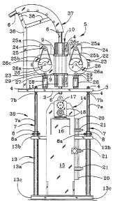
Referring now to FIGURES 3 and 4 of the drawings, in
another preferred embodiment of the invention a coiled
tubing injector with a snubbing-type jack or lifting
mechanism and oscillator (coiled tubing injector apparatus)
for running coiled tubing 6 in a well, is generally
illustrated by reference numeral 5 and includes an
oscillator 22, which is identical to the oscillator 22
detailed in the tubular injector apparatus 1 illustrated in
FIGURES 1, 1A, 1B and 2. However, as illustrated in FIGURES
3 and 4, the snubbing-type jack or lifting mechanism 39 does
not directly handle the coiled tubing 6 and the vibration
isolators or reflectors 28 are mounted by means of the
reflector mount pins 29 on a base plate 3, which is seated
on four threaded pistons 7b that are extendible in double-
action service from corresponding cylinder housings 7a of
four fluid cylinders 7. Each of the threaded ends of the
pistons 7b is typically extended through an opening (not
illustrated) drilled or otherwise provided in the base plate
3 and is secured in place by means of nuts 4 on the top and
bottom of the base plate 3, as illustrated. The bottom ends
of each cylinder housing 7a of the fluid cylinders 7 are
-18-
CA 02335910 2000-12-21
WO 99/67502 PCT/US99/13881
seated in a corresponding one of four cylinder housing
mounts 8 and a mount pin 8a extends through registering
openings (not illustrated) provided in each cylinder housing
7a and the corresponding cylinder housing mount 8, to
facilitate removably mounting each fluid cylinder 7 in the
corresponding cylinder housing mount 8. Each of the
cylinder housing mounts 8 is, in turn, welded or otherwise
fixed to a system of cross-members 13b that connect the four
vertically-oriented frame legs 13a to define a mount frame
13, and facilitate supporting the oscillator 22 above the
mount frame 13, such that the oscillator 22 can be raised
and lowered with respect to the mount frame 13 by operation
of the respective fluid cylinders 7. In a preferred
structure, the four frame legs 13a are supported by the
cross-members 13b to define a mount frame 13 that further
encompasses a coiled tubing injector 14, having an injector
housing 15, as further illustrated in FIGURES 3 and 4. The
coiled tubing injector 14 is typically a conventional coiled
tubing injector designed to inject the coiled tubing 6 into
and from a well (not illustrated) and typically rests on the
wellhead or other well structure or on the ground (not
illustrated). The coiled tubing injector 14 includes a
motor mount bracket 16 which seats an injector motor 17,
fitted with a gearbox 18. Multiple tubing grippers 19 are
provided in a gripper housing 20, the latter of which is
fitted with gripper tensioners 21 to facilitate gripping the
coiled tubing 6 and inserting the coiled tubing 6 into the
well and removing the coiled tubing 6 from the well, in
conventional fashion. The coiled tubing 6 is typically
-19-
CA 02335910 2000-12-21
WO 99/67502 PCT/US99/13881
secured when necessary in the oscillator 22 by clamps such
as the rod~clamps 10, having clamp jaws 11, connected by jaw
bolts 12 and nuts 4, as further illustrated in FIGURES 3 and
4. Accordingly, it will be appreciated from a consideration
of FIGURES 3 and 4 that the coiled tubing 6 is
conventionally wound on a tubing reel (not illustrated) and
extends from the tubing reel to a coiled tubing guide 37,
where the coiled tubing 6 projects through the top rod
clamp 10, the tubular stem 9 in the oscillator 22, the
bottom rod clamp 10 and through the coiled tubing injector
14 that serves to insert the coiled tubing 6 into a well
bore (not illustrated) and remove the coiled tubing 6 from
the well bore, as desired, according to the knowledge of
those skilled in the art.
Referring again to FIGURES 1 and 2 of the drawings the
snubbing jack 30 element of the tubular injector apparatus
1 of this invention is a typical well servicing system
device used in many applications where there is no overhead
derrick or other pipe-handling apparatus. The snubbing jack
30 is mounted on an oil or gas well (not illustrated),
provided with a wellhead or other well structure (also not
illustrated), typically fitted with a blowout preventer 31
(FIGURE 2). As further illustrated in FIGURE 2, the
snubbing jack 30 is secured to the blowout preventer 31,
typically by means of a spool 32, having an upper flange
32a, attached to the bottom of the snubbing jack 30, as
hereinafter described, and a lower flange 32b, attached to
the blowout preventer 31. The blowout preventer 31 is
standard or conventional in design and typically includes an
-20-
CA 02335910 2000-12-21
WO 99/67502 PCT/US99/13881
internal bag mechanism (not illustrated) which may be
selectively pressurized to close around a jointed tubular 2
(FIGURE 1), that extends through the blowout preventer 31,
- to prevent leakage between the tubular 2 and the blowout
preventer 31 as the tubular 2 is advanced into and out of
the well bore (not illustrated) of the oil or gas well. The
blowout preventer 31 is typically mounted on additional
conventional ram-type blowout preventers (not illustrated)
which are supported on a master valve (not illustrated),
mounted on a wellhead (not illustrated), secured on the
upper end of the well casing. As further illustrated in
FIGURE 1, the snubbing jack 30 includes a stabilizing tube
assembly 34 which is telescopically extendible from a tube
assembly cylinder 34a, centrally mounted on a bottom
cylinder plate 35, as illustrated in FIGURE 2. A top
cylinder plate 40 is provided on the upper end of the
stabilizing tube assembly 34, and a pair of large cylinder
assemblies 41 and a pair of small cylinder assemblies 42 are
mounted between the bottom cylinder plate 35 and top
cylinder plate 40, for selectively raising and lowering the
top cylinder plate 40, as hereinafter further described.
Each of the large cylinder assemblies 41 includes a large
cylinder 41a and a large cylinder piston rod 41b,
telescopically extendible from each large cylinder 41a.
Each large cylinder 41a is provided with a large cylinder
base flange 41d, typically bolted to the bottom cylinder
plate 35, as illustrated in FIGURE 2. The upper end of each
large cylinder piston rod 41b is fitted with a piston rod
flange 41e, as illustrated in FIGURE 1, and each piston rod
-21-
CA 02335910 2000-12-21
WO 99/67502 PCT/US99/13881
flange 41e is typically bolted to the underside of the top
cylinder plate 40. Each small cylinder assembly 42 includes
a small cylinder 42a and a small cylinder piston 42b,
slidably extendible from the small cylinder 42a. As
illustrated in FIGURE 2, the bottom end of each small
cylinder 42a is provided with a small cylinder base flange
42d, typically bolted to the bottom cylinder plate 35. The
upper end of each small cylinder piston rod 42b is provided
with a piston rod flange 42e, which is typically bolted to
the underside of the top cylinder plate 40. Each large
cylinder assembly 41 and small cylinder assembly 42 is
typically a conventional, double-acting hydraulic unit
designed for introduction of hydraulic power fluid into the
large cylinder 41a and small cylinder 42a, typically through
a hydraulic power fluid network 160, which is connected to
a source of hydraulic fluid and a control system (not
illustrated) according to the knowledge of those skilled in
the art. Accordingly, the large cylinder piston rod 41b and
small cylinder piston rod 42b may be selectively extended
from and retracted into the respective large cylinder 41a
and small cylinder 42a by application of hydraulic pressure,
in conventional fashion.
As further illustrated in FIGURE 1, a traveling slip
assembly 33 is mounted on the top cylinder plate 40. The
large cylinder assemblies 41 and small cylinder assemblies
42 are operated to~selectively raise and lower the traveling
slip assembly 33 on the top cylinder plate 40, and
accomplish running and pulling the tubular 2 in the well
bore during snubbing and lifting operations of the snubbing
-22-
CA 02335910 2000-12-21
WO 99/67502 PCT/US99/13881
jack 30, as hereinafter described. As further illustrated
in FIGURE~2, the large cylinder assemblies 41 and small
cylinder assemblies 42 are mounted on the bottom cylinder
plate 35 in alternating and symmetrical relationship around
the stabilizing tube assembly piston 34 and stabilizing tube
assembly cylinder 34a. Such symmetrical arrangement permits
the application of balanced forces to the top cylinder plate
40 when using either or both sets of cylinder assemblies 41
and 42, as needed, to raise or lower the traveling slip
assembly 33.
Referring again to FIGURE 1, bottom stanchions 185
extend upwardly from the rectangular top cylinder plate 40
at the respective corners thereof, and a rectangular bottom
plate 184 is supported on the bottom stanchions 185. Middle
stanchions 183 extend upwardly from the bottom plate 184 at
respective corners thereof and a rectangular middle plate
182 is supported on the middle stanchions 183. The
traveling slip assembly 33, supported on the top cylinder
plate 40, extends through aligned slip assembly openings
(not illustrated) provided in the bottom plate 184 and
middle plate 182, respectively. Top stanchions 181 extend
upwardly from the middle plate 182 at respective corners
thereof and a top plate 180 is supported on the middle
stanchions 181. A tubular opening (not illustrated) is
provided in the top plate 180 for accommodating the
assembled, vertical tubular 2. A tubing tong unit or rotary
table 43, the purpose of which will be hereinafter further
described, is mounted on a table stanchion 186, supported on
the top plate 180 and the rotary table 43 is positioned
-23-
CA 02335910 2000-12-21
WO 99/67502 PCT/US99/13881
above the top plate 180. Accordingly, as the rotary table
43 is raised and lowered with the traveling slip assembly 33
on the top cylinder plate 40 and the tubular 2 is inserted
into or removed from the well bore responsive to operation
of the large cylinder assembly 41 and small cylinder
assembly 42, as hereinafter further described, the rotary
table 43 is selectively operated to rotate the tubular 2
about its axis, in order to perform cleanout and drilling
operations in the well bore and facilitate forming or
breaking joints between tubular segments. A work platform
44 is supported on a frame 45, secured to the tube assembly
34a cylinder by means of a mounting plate 50. The work
platform 44 serves to support operating personnel for the
snubbing jack 30, and is typically the location of the
control panels (not shown), used in operating the snubbing
jack 30. A safety guard ring 46 is provided on the frame
45, typically on the middle stanchions 183, and encircles
the traveling slip assembly 33 for safety purposes. As
illustrated in FIGURE 2, the bottom plate 35 (upon which the
large cylinders 41a, small cylinders 42a and tube assembly
cylinder 34a are mounted) is supported on a mounting flange
150, supported on the top frame plate 170 of a fixed slip
assembly frame 51, which further includes a bottom frame
plate 172 and vertical frame stanchions 171 that extend
through respective corners of the top frame plate 170 and
bottom frame plate 172. A top slip assembly 52 is attached
to the bottom surface of the top frame plate 170, in
communication with the mounting flange 150, through the top
frame plate 170. A bottom slip assembly 53, axially aligned
-24-
CA 02335910 2000-12-21
WO 99/67502 PCT/US99/13881
with the top slip assembly 52 and with the well bore, is
attached to the top surface of the bottom frame plate 172,
in communication with the blowout preventer 31, through the
- bottom frame plate 172 and the spool 32. The top slip
assembly 52 is operated to engage or grip the assembled
tubular 2 as the tubular 2 is pushed into the well bore
against well pressure by operation of the traveling slip
assembly 33, during snubbing operation of the snubbing jack
30, as hereinafter further described. In similar fashion,
the bottom slip assembly 53 is operated to grip the tubular
2 as the tubular 2 is inserted into or extended from the
well bore, when the weight of the assembled tubular 2
exceeds the well bore pressure. A mast or gin pole 54 is
mounted on a support member 55, secured to the frame 51, for
lifting or lowering tubing lengths or segments (not
illustrated) when assembling or disassembling the tubular 2
from the tubing segments before and after use, respectively,
as hereinafter described. The gin pole 54 is typically
characterized by a standard, hydraulically-extendible mast
which includes a pulley 60, over which a line (not shown) is
run to facilitate raising and lowering the tubular segments
of the tubular 2.
In a typical snubbing operation using the snubbing jack
in cooperation with the oscillator 22, each tubular
25 segment (not illustrated) of the tubular 2 is individually
raised by operation of the gin pole 54, to a position above
the rotary table 43 and the tubular stem 9 of the oscillator
22, and then lowered through the rod clamps 10, the tubular
stem 9 and the traveling slip assembly 33, into the snubbing
-25-
CA 02335910 2000-12-21
WO 99/67502 PCT/US99/13881
jack 30. As the tubular segments are rotated by operation of
the rotary table 43 and threaded together in the nascent
tubular 2, the large cylinder assembly 41 and small cylinder
- assembly 42 are operated to raise the traveling slip
assembly 33, which is then operated in conventional fashion
to engage the tubular 2, which moves freely in the tubular
stem 9 and rod clamps 10 of the oscillator 22. The
traveling slip assembly 33 is next lowered with the top
cylinder plate 40 by operation of the large cylinder
assembly 41 and small cylinder assembly 42, forcing the
tubular 2 downwardly through the upper fixed slip assembly
52, lower fixed slip assembly 53 and blowout preventer 31,
and into the well bore (not illustrated). When the large
cylinder piston 41b and small cylinder piston 42b are fully
retracted into the large cylinder 41a and small cylinder
42a, respectively, the upper fixed slip assembly 52 or lower
fixed slip assembly 53 is operated to grip and hold the
tubular 2 against either the weight of the tubular 2 or
against the well pressure, depending on operating
conditions. Simultaneously, the traveling slip assembly 33
is released from the tubular 2 and raised by operation of
the large cylinder assembly 41 and small cylinder assembly
42, and then operated to again grip and then force another
increment of the tubular 2 downwardly by lowering operation
of the large cylinder assembly 41 and small cylinder
assembly 42. The length of each raised or lowered increment
of the tubular 2 depends on the degree of extension of each
large cylinder piston 41b and small cylinder piston 42b from
the large cylinder 41a and small cylinder 42a, respectively.
-26-
CA 02335910 2000-12-21
WO 99/67502 PCT/US99/13881
As this process is repeated, the tubular 2 is assembled and
forced downwardly into the well bore against bore pressure
as the multiple tubing segments are connected in
- conventional manner. The snubbing jack 30 is operated to
lift the assembled tubular 2 from the well bore, as desired,
by operating the traveling slip assembly 33 to sequentially
engage the tubular 2 at the retracted or lowered position of
the large cylinder assemblies 41 and small cylinder
assemblies 42, and then operating the large cylinder
assemblies 41 and small cylinder assemblies 42 to lift the
tubular 2 from the well bore. The upper fixed slip assembly
52 or lower fixed slip assembly 53 is operated to engage and
hold the tubular 2 while the disengaged traveling slip
assembly 33 is moved from the upper to the lower position to
re-engage the tubular 2, and then to release the tubular 2
while the traveling slip assembly 33 lifts the tubular 2.
Simultaneously, the tubular 2 extends through and is rotated
by the rotary table 43, to facilitate disassembly of the
tubular 2 by successively unthreading the tubular segments
(not illustrated) from the tubular 2.
The snubbing jack 30 is characterized by maximum
stability imparted by the stabilizing tube assembly piston
34, the stabilizing tube assembly cylinder 34a arid the
snubbing and lifting speeds of the snubbing jack 30 can be
varied, as desired, by selective operation of the large
cylinder assembly 41 and small cylinder assembly 42. The
selectivity provided in the speed of operation cf the
snubbing jack 30 permits correlation of the snubbing and
lifting speeds of the tubular 2 with the weight cf the
-27-
CA 02335910 2000-12-21
WO 99/67502 PCT/US99/13881
tubular 2 and other operating conditions of the snubbing
jack 30. 'During both snubbing and lifting operations, the
weight of the tubular 2 varies as the length of the tubular
- 2 increases and decreases. The weight of the tubular 2 is
continually monitored, and the snubbing or lifting speed
varied in inverse relationship to the weight capacity. The
maximum weight of the tubular 2 is handled at the lowest
operating speed of the large cylinder assembly 41 and small
cylinder assembly 42, and the speed of the large cylinder
assembly 41 and small cylinder assembly 42 is increased to
a maximum at the minimum weight of the tubular 2. For
example, as the tubular 2 is initially lifted from the well
bore after the snubbing operation, the maximum weight of the
tubular 2 is exerted on the snubbing jack 30, since most of
the tubular 2 is suspended in the well bore. As the tubular
2 is rotated by the rotary table 43 as it is pulled from the
well bore, the tubular segments are removed from the tubular
2 and the tubular 2 becomes lighter. Accordingly, when the
tubular 2 has initially begun to be raised from the well
bore, the snubbing jack 30 is operated at the lowest speed.
As the tubular 2 is disassembled at the tubular joints (not
illustrated), the weight of the tubular 2 is reduced and the
snubbing jack 30 is shifted to a higher operating speed.
The system speed sequentially increases as the weight of the
tubular 2 decreases, until the last tubular segment is
extracted from the well bore at maximum speed. In similar
fashion, during the snubbing operation as the tubular 2 is
inserted or lowered into the well bore, the speed of the
-28-
CA 02335910 2000-12-21
WO 99/67502 PCT/US99/13881
snubbing jack 30 is decreased to correlate with the
increasing~weight of the nascent tubular 2.
In operation, the embodiment of the tubular injector
apparatus 1 of this invention illustrated in FIGURES 1, 1A,
1B and 2 is used as follows: During a typical tubular
running operation the snubbing jack 30 is operated as
indicated above, with the tubular 2 extending through the
rod clamps 10 and the tubular stem 9 of the oscillator 22
and through the snubbing jack 30, as illustrated in FIGURE
1. Either the oscillator 22 may be "stripped" on the
tubular 2 or the tubular 2 may be extended through the
tubular stem 9 of the oscillator 22 and then through the
snubbing jack 30 as described above, to facilitate operation
of the snubbing jack 30 in conventional fashion with the
tubular 2 running freely through the tubular stem 9 of the
oscillator 22. Under circumstances where a difficulty in
insertion or removing the tubular 2 into or from the well
(not illustrated) is encountered during normal operation of
the snubbing jack 30, the rod clamps 10 located on both ends
of the vertically-oriented tubular stem 9 are tightened to
secure the oscillator 22 on the tubular 2. The clamping of
the rod clamps 10 on the tubular 2 is effected by tightening
the nuts 4 located on the jaw bolts 12 to in turn, tighten
the clamp jaws 11 of the rod clamps 10 on the tubular 2 and
secure the tubular 2 in place in the tubular stem 9 of the
oscillator 22. When this is accomplished, the snubbing jack
is operated as indicated above to first release the
traveling slip 33, maintaining the stationary top slip
assembly 52 and bottom slip assembly 53 in place on the
-2 9-
CA 02335910 2000-12-21
WO 99/67502 PCT/US99/13881
tubular 2. The large cylinder assemblies 41 and small
cylinder assemblies 42 are then operated to raise the top
cylinder plate 40 and upper unit of the snubbing jack 30,
tension the vibration isolators or reflectors 28 and load
the rod clamps 10. The stationary top slip assembly 51 and
bottom slip assembly 52 are then released from the tubular
2 to release the load represented by the downhole segment of
the tubular 2 from the top slip assembly 52 and the bottom
slip assembly 53. When this is accomplished, the entire
load of the tubular 2 is supported by the rod clamps 10 of
the oscillator 22 and the oscillator 22 is isolated from the
snubbing jack 30 as to vibration, by means of the vibration
isolators or reflectors 28, which are now further compressed
on the reflector mount pins 29 to act as vibration
isolators, reflectors and insulators during operation of the
oscillator 22. Since the oscillator 22 is now firmly
attached to the tubular 2 and is vibrationally isolated from
the snubbing jack 30, operation of the eccentric drive
motors 24, which are typically hydraulic, is effected to
rotate the respective eccentrics 26 and effect a vibration
and oscillation at a resonant frequency to the tubular 2.
In the course of applying a resonant frequency to the
tubular 2, the oscillator 22 generates an axial sinusoidal
force that can be tuned to a specific frequency within the
operating range of the oscillator 22. The force generated
by the oscillator 22 acts on the tubular 2 to create axial
vibration of the downhole segment of the tubular 2. When
tuned to a resonant frequency of the system, energy
developed at the oscillator 22 is efficiently transmitted to
-30-
CA 02335910 2000-12-21
WO 99/67502 PCT/US99/13881
the stuck downhole segment of the tubular 2, with the only
losses being those that are attributed to frictional
resistance. The effect of the tubular 2 reactance is
- eliminated because mass induction is equal to spring
capacitance at the resonant frequency. Other aspects of the
oscillator 22 operation is the fluidization of the granular
particles downhole in the event that the cause of the stuck
downhole segment of the tubular 2 results from a cave-in or
silting of the hole or jamming of the downhole objects to
create a mechanical wedging action against the downhole
segment of the tubular 2. When excited by a vibration from
the oscillator 22, the granular particles are transformed
into a fluidic state that offers little resistance to the
movement of the tubular 2 upwardly or downwardly by
operation of the snubbing jack 30. In effect, the granular
media takes on the characteristics and properties of a
liquid and facilitates extraction of the tubular 2 by
elevating and/or lowering the tubular 2, as described above.
After the tubular 2 is loosened in the well, the stationary
top slip assembly 52 and bottom slip assembly 53 are again
operated in the snubbing jack 30 to engage the tubular 2.
The large cylinder assemblies 40 and small cylinder
assemblies 42 are then operated to lower the top cylinder
plate 40 and the upper unit of the snubbing jack 30, remove
the tension from the vibration isolators or reflectors 28
and unload the rod clamps 10. The rod clamps 10 are then
loosened to free the oscillator 22 from the tubular 2.
Furthermore, the top slip assembly 52, the bottom slip
assembly 53, as well as the traveling slip assembly 33, are
-31-
CA 02335910 2000-12-21
WO 99/67502 PCT/US99/13881
caused to re-engage the tubular 2, wherein the snubbing jack
30 is operated as discussed above to "run" the tubular 2 in
and out of the well.
' Referring now to FIGURES 3 and 4 of the drawings in
another preferred embodiment of the invention the tubular
injector with snubbing jack and oscillator of this
invention, designated a coiled tubing injector apparatus 5,
is designed to handle coiled tubing as heretofore described.
As further heretofore described, the oscillator 22 is the
same in design as the oscillator 22 utilized in the tubular
injector apparatus 1 illustrated in FIGURES 1, 1A, 1B and 2.
However, the lifting mechanism or snubbing-type jack 39
includes four fluid cylinders 7, with the cylinder housings
7a secured to the four corners of a mount frame 13 as
heretofore described and as illustrated in FIGURES 3 and 4.
Accordingly, operation of the respective pistons 7b in the
cylinder housing 7a raise and lower the base plate 3 upon
which the oscillator 22 is mounted. Appropriate hydraulic
lines and motors (not illustrated) are attached to the
typically double-action fluid cylinders 7 for operation
thereof, according to the knowledge of those skilled in the
art. Furthermore, the "gooseneck" coiled tubing guide 37 is
positioned above the oscillator 22 by means of the
"gooseneck" support 38 and serves to feed the coiled tubing
6 from a reel (not illustrated) through the top rod clamp 10
and into the tubular stem 9 of the oscillator 22, and from
the tubular stem 9 downwardly through the bottom rod clamp
10 and into the coiled tubing injector 14, fitted with a
conventional tubing grippers 19, as illustrated in FIGURE 4.
-32-
CA 02335910 2000-12-21
WO 99/67502 PCT/US99/1388I
Consequently, the coiled tubing 6 can be "run" in a well
(not illustrated) located beneath the frame 13 by operation
of the coiled tubing injector 14 in conventional fashion.
Under circumstances where an obstacle is encountered
downhole in the well and the coiled tubing 6 cannot be
either raised or lowered, as the case may be, by operation
of the coiled tubing injector 14, the oscillator 22 can be
secured to the coiled tubing 6 in the same manner as
illustrated above with respect to the tubular injector
apparatus 1 illustrated in FIGURES l, 1A, 1B and 2,
utilizing the rod clamps 10. The fluid cylinders 7 are then
operated to raise the base plate 3 and apply a compressive
load on the vibration isolators or reflectors 28, after
which the tubing grippers 19 are released from the coiled
tubing 6 by operating the gripper tensioners 21 in the
coiled tubing injector 14 in conventional fashion and
facilitate release of the load on the coiled tubing 6 by the
coiled tubing injector 14. Consequently, the coiled tubing
injector 14 is completely isolated from the oscillator 22
with regard to vibration by operation of the vibration
isolators or reflectors 28, which are now compressed because
of the load of the downhole coiled tubina 6 on the
respective rod clamps 10 of the oscillator 22. The
oscillator 22 is then operated as described above with
respect to the tubular injector apparatus 1 illustrated and
described with regard to FIGURES 1, 1A, 1B and 2, to loosen
the coiled tubing downhole as the snubbing jack 39 is
operated up and/or down to move the oscillator 22 and coiled
tubing 6 up and/or down in the well. After the coiled tubing
-33-
CA 02335910 2000-12-21
WO 99/67502 PCT/US99/13881
6 is loosened in the well, the gripper tensioners 21 in the
coiled tubing injector 14 are operated to cause the tubing
grippers 19 to again engage the coiled tubing 6, the fluid
cylinders 7 are operated to lower the base plate 3 and
"unload" the vibration isolators or reflectors 28 and the
rod clamps 10 are loosened on the coiled tubing 6 as the
weight of the coiled tubing 6 is transferred to the coiled
tubing injector 14. The coiled tubing injector 14 is then
operated as heretofore described to "run" the coiled tubing
6 in the well.
It will be appreciated by those skilled in the art that
one of the advantages of utilizing the coiled tubing
injector apparatus 5 aspect of the invention illustrated in
FIGURES 3 and 4, is the facility for manipulating the coiled
tubing 6 directly from the tubing reel (not illustrated)
without the necessity of cutting the coiled tubing 6 during
normal operations of the coiled tubing injector 14. This
facility is extended to circumstances where the coiled
tubing 6 may be stuck downhole and may require the operation
of the oscillator 22 to free the coiled tubing 6.
Furthermore, in both of the embodiments illustrated in the
drawings, a primary advantage of using the snubbing jack 30
and snubbing-type jack or lifting mechanism 39 in the
respective embodiments of the invention, is the elimination
of the necessity of using a derrick or overhead support
device or structure for "running" coiled tubing or other
tubulars, including drill pipe and the like, in and out of
the well. Consequently, both the tubular injector apparatus
1 illustrated in FIGURES 1, 1A, 1B and 2, and the coiled
-34-
~n
CA 02335910 2003-08-22
WO 99167502 PC'IIUS99/13881
tubing apparatus 5, illustrated in FIGURES 3 and 9, can be
easily used on offshore platforms, as well as on land, to
effect the running of drill pipe and to facilitate freeing
of stuck drill pipe downhole utilizing the oscillator 22.
While the preferred embodiments of the invention have
been described above, it will be recognized and understood
that various modifications may be made in the invention and
the appended claims are intended to cover all such
modifications which may fall within the spirit and scope of
the invention.
-35-