Note: Descriptions are shown in the official language in which they were submitted.
CA 02340533 2001-03-13
FIBER OPTIC BASED SECURITY SYSTEM
FIELD OF THE INVENTION
The present invention relates to a compact and practical security system
s using fiber optics.
SUMMARY OF THE INVENTION
The present invention uses light propagating in a loop of optical fiber as a
means to protect an article from theft. The fiber is looped around the
article, such
to as shown in Figure 3. At one end of the loop, a LED emits light into the
fiber, and
at the other end a photoreceptor receives the light after its travel in the
fiber. The
photoreceptor is also linked to an alarm system which is activated if the
light
received is lower than a pre-defined threshold. Consequently, should somebody
attempt to steal the object that is to be protected by cutting the optical
fiber, the
u~ alarm system is immediately activated. Advantageously, all the components
of the
invention with the exception of the fiber loop, are conveniently included in a
single
casing.
BRIEF DESCRIPTION OF THE DRAWINGS
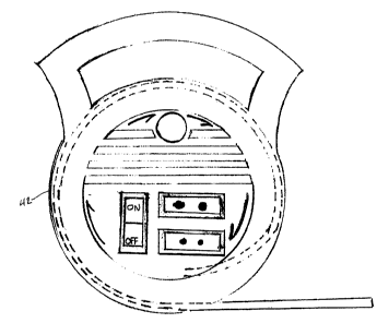
2o FIG. 1 is a front elevation partially transparent view of a closed casing
including a security system according to a preferred embodiment of the
invention.
FIG. 2 is a front elevation view of the casing of FIG. 1 when opened.
2s FIG. 3 is a side view of a fiber loop according to the preferred embodiment
of the invention.
FIG. 4 is a schematic view showing the connection of the LEDs shown in
FIGs. 1 and 2.
FIG. 5 is an exploded view of the casing of FIG. 1.
CA 02340533 2001-03-13
FIG. 6 is a schematic representation of a circuit used for a security system
according to the present invention.
s FIG. 7 is a perspective view of a security system according to a second
embodiment of the present invention.
FIG. 8 is a partially transparent view of a padlock for use in another
embodiment of the invention.
to
DESCRIPTION OF PREFERRED EMBODIMENTS OF THE INVENTION
Referring to FIG. 6, there is shown a schematic representation of the
system 10 according to a preferred embodiment of the present invention. The
system 10 first includes a fiber loop 12, defining an input branch 14 and an
output
~ 4~ branch 16. The input branch 14 is connected to a light emitter 18, for
example a
LED, which may be connected to a pulse generator 19. The output branch 16 is
connected to a light detector 20. In this manner, if the integrity of the
fiber loop is
compromised, the light level received at the light detector 20 will be
lowered.
Means 22 to detect tampering of the fiber loop 12 are provided, and are
connected
2o both to the detector 20 and an alarm 24. The alarm 24 is activated if the
light level
at the detector is lower than a predetermined threshold. Preferably, the means
22
are also connected to a pair of green and red LEDs 26 and 28, which
respectively
indicate if the system is activated or not. The system 10 is preferably
powered by
an ordinary power outlet to which is connected an AC/DC converter 30. A
battery
2s or set of batteries 32 may be provided as a backup power source. An ON/OFF
switch 34 is also provided.
Referring to FIGs. 3 and 4, there is shown a preferred embodiment of the
fiber optic loop 12. The loop 12 is wrapped around a portion 36 of an article
to be
3o protected. The article in question may advantageously be stored outdoors,
such as
for example a bicycle, a motorcycle, camping equipment, a lawnmower, etc. The
CA 02340533 2001-03-13
3
two branches 14 and 16 are preferably connected to a connector 38, from which
they emerge bundled together and protected by a sleeve 40. The length of the
branches is preferably long enough to span the distance from the object to be
protected and a neighbouring residence or other power source. Branches 14 and
s 16 are again separated so that they may be connected to the emitter 18 and
detector 20.
Referring to FIGs. 1, 2 .and 5, there is shown how the components of the
alarm system according to the present invention may advantageously be
installed
to in a casing 42. Such an embodiment makes the system 10 very convenient to
install, carry or sell. Preferably, the casing 42 is round shaped, and is
provided
with an inner cavity in which the fiber loop 12 may be stored when the system
is
not in use.
is Referring to FIG. 7, there is shown another embodiment of the invention
where the system 10 is part of a central security system of a residence. The
present invention may therefore not be provided with an integral alarm but
simply
be connected to the alarm of the central system. The components of the control
circuit may also all be integrated into the central system.
Referring to FIG. 8, there is shown another embodiment of the invention
where the fiber loop 12 is hidden into the fastening portion 43 of a padlock
44. In
this manner, cutting the padlock would also cut the fiber optic loop,
therefore
activating the alarm.
2s
Although the present invention has been described by way of a preferred
embodiment thereof, it should be understood that modifications within the
scope of
the invention are contemplated by the present application.
