Note: Descriptions are shown in the official language in which they were submitted.
CA 02344930 2002-07-09
DATA MONITORING SYSTEM
Field of Invention
This invention relates to systems for the generation, production, processing,
and transmission of audio, video, and data.
Background of the Invention
Modern facilities for the generation, production, processing, and transmission
of audio, video, and data are often composed of many interconnected pieces of
equipment from different manufacturers. Control and monitoring of the many
different pieces of equipment is a frequent problem. Although remote control
protocols have been adopted to allow control of equipment from a remote
location,
different manufacturers often adopt vastly different protocols. Additionally,
monitoring the output of the equipment is similarly difficult.
For example, in order to monitor the outputs of ten different units of video
processing equipment, ten different cables must be employed to carry the
separate
video signals to the monitoring location. Then, ten monitors are required to
view the
video signals simultaneously. A video switches can also be connected to the
cables to
select a single signal for viewing on one suitable display device. Or, for
viewing
several feeds simultaneously on a single monitor, a video multiplexes can be
used,
such as that described in U.S. Patent 4,266,242, entitled "Television Special
Effects
Arrangement". Although the use of a video switches or a video multiplexes
reduces
the number of video monitors required, a separate cable is still required to
carry the
signal from the desired monitoring point to the selector or multiplexes. Since
a
typical facility can contain hundreds or thousands of different pieces of
equipment,
either massive cabling schemes must be implemented or monitoring capability
must
be limited to a few selected pieces of equipment.
Networking techniques have evolved to permit remote control of equipment.
Manufacturer-specific control schemes have largely given way to standard-based
control schemes using the Internet Protocol, such as SNMP (Simple Network
Management Protocol). Equipment implementing a standard-based networking
control protocol can be connected together on a single data communications
network
such as Ethernet and managed by a single operator station. Commands sent from
the
CA 02344930 2002-07-09
operator station are transmitted through the data communications network
bearing an
address specific to the unit of equipment being controlled. The unit of
equipment
may also transmit status and alarm information to other pieces of equipment or
the
operator station. Alternatively, a facility controlled in such a fashion may
be operated
remotely by an operator using a computer connected through the Internet.
However, the standards-based methods do not provide a method for
monitoring the streams of video, audio and/or data being generated, switched,
or
processed by the equipment in the facility.
Summary of the Invention
The present invention adds monitoring capability to equipment located within
a video, audio and/or data production facility by placing a sampling device in
the
equipment to be so monitored. The sampling device is connected to a data
communications network and transmits a continuous representation of the video,
audio or data being sampled over a data communications network in response to
commands from an operator station. To accommodate monitoring of large numbers
of sampling devices on a single network, the sampling device may encode and/or
compress the video, audio or data being monitored prior to transmitting the
sample
over the network. The sampling device may also further reduce its contribution
to
network loading by providing an instant sample of the, stream being sampled,
such as
a single video frame, either a single time, or repeatedly at regular
predetermined time
intervals.
The present invention thus provides a data monitoring system comprising a
signal processing block, at least one output connected to said processing
block, a
compressor connected to said output of said processing block, and a data
network
connected to said compressor and to at least one monitoring station, whereby
said
monitoring station receives an output of said compressor in order to monitor
the
output of said signal processing block.
The present invention further provides a television monitoring system
comprising a television signal processing block, at least one output connected
to said
processing block, a video compressor connected to said output of said
processing
block, and a data network connected to said video compressor and to at least
one
-2-
CA 02344930 2002-07-09
monitoring station, whereby said monitoring station receives an output of said
video
compressor in order to monitor the output of said signal processing block.
The present invention further provides a television monitoring system
comprising a television signal processing block, at least one video output
connected to
said processing block, a video compressor connected to said video output, at
least one
audio output connected to said processing block, an audio compressor connected
to
said audio output, and a data network connected to said video compressor and
said
audio compressor, and to at least one monitoring station whereby the data
network
receives outputs of said video compressor and said audio compressor in order
to
monitor outputs of said signal processing block.
In a further aspect of the system of the invention, signals received by said
data
network are controlled by commands transmitted from said data network.
Brief Description of the Drawings
In drawings which illustrate by way of example only a preferred embodiment
of the invention,
Figure 1 is a block diagram showing the typical equipment connection diagram
of a
small television production facility,
Figure 2 is a block diagram showing the small television production facility
of Figure
1 with the addition of monitoring capability through the use of technology
from the
prior art, and
Figure 3 is an internal block diagram of a television equipment frame
containing a
preferred embodiment of the invention.
Detailed Description of the Invention
Fig. 1 shows a block diagram of a hypothetical typical television production
facility. Modern television facilities may have hundreds of video, audio and
data
inputs and outputs; however, for ease and clarity of illustration, the
television
production facility depicted in Fig. 1 is shown with a small number of inputs
and
outputs by way of example.
-3-
CA 02344930 2002-07-09
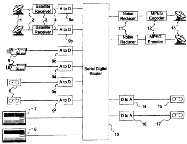
Satellite antennae 1 are connected through radio frequency cables 2 to
satellite
receivers 3, each of which processes and selects a channel for output to the
facility.
This channel may consist of one or more channels of video and associated audio
and
data. Satellite receivers 3 output video, audio and associated data which are
converted in analog to digital converters 9a and 9b to the preferred SDI
(Serial Digital
Interface) format. In the SDI format, the video is converted to a digital
signal at the
rate of 270 megabits per second (Mbps) with digital audio in the AES/EBU
format
and associated data signals interleaved within the digital signal. The SDI
signal
format is well known in the art and is standardized in the SMPTE-295M standard
of
the SMPTE (Society of Motion Picture and Television Engineering).
In similar fashion, television cameras 5 output video signals, and their video
signals are converted into SDI signals in analog to digital converters 9c and
9d. For
ease and clarity of illustration, the audio channels associated with
television cameras
are not shown, but are handled in the same manner.
Video tape player/recorders (VTRs) 6 also provide video, audio and data
sources, and the video, audio, and associated data are converted in analog to
digital
converters 9e and 9f. Digital video servers 7 and 8 also provide video and
audio
inputs to the facility, but since each provides outputs already in the SDI
format, no
analog to digital conversion step is required.
The outputs of analog to digital converters 9a through 9f, and digital video
servers 7 and 8, all in the SDI format, are routed to serial digital muter 10,
which can
select any input and reproduce it on one or more outputs. In Fig. 1, inputs to
serial
digital router 10 are shown on the left side, while the outputs are shown to
the right
side. In the hypothetical television facility of Fig. l, two outputs of serial
digital
muter 10 are connected to noise reducers 1 l, which reduce noise components of
the
input video signal which can adversely affect subsequent video compression.
The
outputs of noise reducers 11, still in SDI format, are connected to MPEG
encoders 12.
The signals are converted into RF and transmitted to communications satellites
at
transmit antennas 13 using techniques well known to one skilled in the art.
The serial
digital muter 10 can be operated to present the same signal to the noise
reducers 11 or
two different signals.
-4-
CA 02344930 2002-07-09
In similar fashion, two other outputs of the serial digital muter 10 are
connected to digital to analog converters 14 and 16, which convert the SDI
signal
back into an analog format. The analog audio and video signals are then
connected to
VTRs 15 and 17.
It is often useful to place monitoring connections at the inputs and/or
outputs
of the various units of equipment shown in Fig. 1. This monitoring serves two
purposes; first to monitor the quality of the outputs of the equipment at
various
processing stages in the facility, and second to pinpoint the location of
equipment
failures in the facility.
Fig. 2 shows the television production facility in Fig. 1 with the addition of
monitoring connections to serial digital muter 20. Digital to analog
converters 22
convert the SDI output signal from serial digital router 20 to an analog
format suitable
for display on standard television monitors 23. In this fashion two different
inputs
from the serial digital router 20 can be displayed on monitors 23.
However, this monitoring capability has the disadvantages of tying up outputs
from the main serial digital router 20, as well as the fact that only inputs
to the serial
digital router 20 can be monitored. If, for example, the input 21 to the
serial digital
router 20 corresponding to camera 23 fails, the prior art monitoring solution
in Fig. 2
cannot determine if the problem is in the camera 23, connecting cable 24, or
in the
analog to digital converter 25.
It is possible to connect additional monitoring cables to camera 23,
connecting
cable 24, and the analog to digital converter 25 however, this increases the
number of
monitoring points required to four times just in the simple facility. Buffer
amplifiers
are required at the monitoring points to avoid changing the amplitude of the
signal at
the facility point being monitored. In addition, unless a suitable video
display device
is provided for each individual signal to be monitored, some separate means of
selecting the video signal to be monitored must be provided. The magnitude of
the
complexity of this monitoring arrangement is apparent even with the small
example
facility illustrated.
Fig. 3 is a detailed block diagram of a preferred embodiment of the invention.
In a preferred embodiment, four video/audio/data processing blocks 52 are
located in
-5-
CA 02344930 2002-07-09
a single rack mounted enclosure, permitting common power supplies and other
support functions to be shared among the processing blocks 52. Each processing
block 52 has audio, video and data inputs 51. The audio may be in analog
format or
may be in a digital form such as a version of AES/EBU (Audio Engineering
Society/European Broadcast Union) which is well known in the art. Similarly,
the
video input to the processing block may be in analog format or in SDI digital
format.
Another input in the group of inputs 51 is an ancillary digital data input
which can
consist of closed captioning data or other data unrelated to the video and
audio signals
in input group 51 but associated with them for the purposes of transmission
and/or
processing. Processing block 52 can perform any of a wide vaxiety of
functions,
including those performed by analog to digital converter 9a shown in Fig. 1.
In a preferred embodiment, processing block 52 has an SDI video output 53,
an audio output 54, and ancillary digital data output 55. Video output 53 is
connected
to an MPEG (Motion Picture Experts Group) compression block 56, which
compresses the SDI interface into a lower bit rate MPEG-1 or MPEG 2 compressed
format. MPEG-1 and MPEG-2 are video compression standards well known in the
art, and described in ISO standard series 13818 documents. Audio output 54 is
compressed using a compatible audio compression format, such as the well-known
MPEG-2 Level 3 (mp3) format, also fully described in the ISO standard series
13818
documents. Ancillary digital data output 55 is also compressed in data
compressor 70
using a suitable data compression format, such as run length encoding or the
LZW
compression format.
In a preferred embodiment, the full-bandwidth 270 Mbps SDI video output 53,
its MPEG-compressed representation, the audio stream compressed by audio
compressor 57, and the ancillary data stream compressed by data compressor 70,
are
connected to LVDS (Low Voltage Differential Signaling) interface 58 which
multiplexes these signals onto enclosure monitoring bus 62 along with the
outputs of
LVDS interfaces 59, 60 and 61. LVDS is a low-voltage differential signaling
standard which allows very high data rates while minimizing crosstalk and
electromagnetic emissions.
In a preferred embodiment, the data contained on enclosure monitoring bus 62
is transported in an SDI format, however enclosure monitoring bus 62 operates
at 810
-6-
CA 02344930 2002-07-09
Mbps, three times the standard 270 Mbps format, which allows three or more SDI
signals to be carried simultaneously. In addition, a preferred embodiment
accepts
commands from Ethernet network 69 which are received by Ethernet interface 68
and
transmitted back through LVDS interface 63 to LVDS interfaces 58, 59, 60 and
61 to
adjust the order and type of the incoming data placed on enclosure monitoring
bus 62.
For example, the LVDS interfaces 58, 59, 60, and 61 can be initially
configured to transmit data to the enclosure monitoring bus 62 operating at
three
times SDI speed in a round-robin format; that is, first LVDS interface 58 can
send an
SDI video frame, followed by an SDI frame from LVDS interface 59, then an SDI
frame from LVDS interface 60, then an SDI frame from LVDS interface 61. Since
in
Fig. 3 there are four LVDS interfaces, the frame rate from each LVDS interface
is
necessarily limited to a maximum of'/4 the standard 30 frames per second. If a
higher-speed enclosure monitoring bus is selected, for example 1.28 Mbps or
four
times the 270 Mbps SDI rate, 30 frames per second can be transmitted over the
enclosure monitoring bus from each of the four LVDS interfaces 58, 59, 60 and
61.
In a preferred embodiment, the LVDS interfaces can be commanded to place
digital data from the MPEG compressor 56 and audio compressor 57 into an SDI
video frame along with ancillary digital data compressed by data compressor
70. In
this manner, full 30 frame per second monitoring of a video stream along with
its
audio track and affiliated data can be performed. In addition, the SDI frame
structure
contains extra space not normally used for carrying video in the SDI format
which can
be utilized for additional data capacity. Ethernet interface 68 receives
commands
from operator stations on Ethernet network 69 which are then transmitted to
the
LVDS interfaces 58, 59, 60 and 61 to change the composition of the data
contained on
enclosure monitoring bus 62 as needed for monitoring a specific processing
block. As
up to twelve or more video processing blocks and associated LVDS interfaces
may be
connected to a single enclosure monitoring bus, this feature is especially
useful to
permit a specific LVDS interface to transmit more of its monitoring
information.
In a preferred embodiment, processing block 52 will also send status and
alarm information to LVDS interface 58. For example, if processing block 52
loses
video or audio input, or detects an internal failure, it generates an alarm
signal. This
information can be included in the ancillary digital data output 55 and sent
to LVDS
CA 02344930 2002-07-09
interface 58, which forwards this data through the enclosure monitoring bus to
LVDS
interface 63 and onward to the Ethernet interface 68 and Ethernet network 69
to
monitoring stations on the Ethernet network. In a preferred embodiment, if
LVDS
interface 58 transmits alarm information, Ethernet interface 68 or monitoring
stations
connected Ethernet network 69 can command LVDS interface 58 to send more
video,
audio, and/or data monitoring information over the enclosure monitoring bus 62
in
order to pinpoint the nature of the failure. Alternatively, LVDS interface 58
can
spontaneously send more information in response to an alarm. This would occur
after coordination with LVDS interface 63 and Ethernet network 68 in order to
avoid
jamming of the network in the event of multiple simultaneous alarms.
In a preferred embodiment, LVDS interface 63 receives the multiplexed video,
audio and data at three times SDI data rate from LVDS interfaces 58, 59, 60
and 61.
The data is demultiplexed, and compressed MPEG video, mp3 audio and data
outputs
67 are sent to Ethernet interface 68. In order to prevent saturation of the
available
bandwidth of the network, the full bandwidth SDI data is compressed in JPEG
compressor 65 before being sent via output 66 to Ethernet interface 68.
Ethernet
interface 68 then determines, in response to commands received over Ethernet
network 69, the destination of the different types of data it receives from
JPEG
compressor output 66 and MPEG video, mp3 audio and data inputs 67.
_g_