Note: Descriptions are shown in the official language in which they were submitted.
CA 02345389 2001-03-23
WO 00/16686 PCT/US99/20464
IMP ,ANT B SENSOR WITH WIRELESS COMMUNICATION
Field of the Invention
This invention relates generally to an implantable sensor with wireless
communication, and particularly, but not by way of limitation, to
physiological
monitoring of pressure or other parameters in humans and animals using a
monitor that is implantable within a heart chamber or elsewhere and is capable
of
wireless communication of sensor information therefrom.
Background
The monitoring of fluid pressure within a body organ provides an
important tool for medical research and clinical diagnosis. For example,
hydrocephalus and head injuries can cause body fluids to build up within the
brain. The resulting fluid pressure buildup can result in death or serious
brain
damage. In another example, urinary dysfunction can cause fluid pressure to
build up in the bladder. In a further example, intrapleural pressure
measurements can be used to monitor the respiration of infants who have been
identified as being at risk for sudden infant death syndrome.
Blood pressure measurements are particularly important for medical
research and diagnosis for a variety of reasons. Such measurements provide
researchers with insight into the physiology and functioning of the heart.
Blood
pressure measurements also provide researchers with useful information
regarding the safety and efficacy of pharmaceuticals and the toxicity of
chemicals. By transducing blood pressure into a signal waveform, a variety of
useful parameters can be extracted. These parameters provide valuable
information for the diagnosis of heart disease. Left ventricular (LV) blood
pressures measurements are particularly important because the left ventricle
chamber of the heart pumps blood to the systemic circulatory system, that is,
throughout the rest of the body.
Comrnon parameters extracted from left ventricular blood pressure
waveforms include peak systolic pressure (the high pressure peak resulting
from
a contraction of the left ventricle chamber of the heart), end diastolic
pressure
(the low pressure valley resulting from expansion of the left ventricle), and
CA 02345389 2001-03-23
WO 00/16686 PCTIUS99/20464
2
maximum dP/dt (a peak value of how fast the pressure (P) changes with time (t)
during a contraction of the left ventricle). These blood pressure measurements
provide helpful diagnostic information to the physician.
For example, maximum dP/dt provides a measure of the work that is
being done by the heart. For certain conditions, such as congestive heart
failure
(CHF), it is desired to reduce the work load on the heart. The treating
physician
can determine how effective a therapy is by determining if the treatment
regimen
has indeed reduced the work load on the heart, as indicated by the maximum
dP/dt signal extracted from the left ventricular blood pressure waveform.
Measurement of left ventricular blood pressure is also useful for titrating
new
drugs for treating heart disease, that is, determining the desired dosage or
concentration of a new drug. Titrating new drugs requires information on how
these drugs are affecting the heart.
For example, beta adrenergic blocking drugs are often effective at
treating arrhythmias and improving patient hemodynamics. However, such
drugs are difficult to titrate. Because left ventricular blood pressure
parameters,
such as maximum dP/dt, provide information on how the heart is functioning,
monitoring these parameters allows a physician to more easily determine the
most appropriate dose of the drug for treating the patient. The maximum dP/dt
signal, if available, could also be used as a feedback mechanism in a system
that
automatically delivers therapy to adjust the work load of the heart. The
delivery
of therapy is automatically adjusted based on the work load of the heart, as
indicated by the maximum dP/dt signal.
In another example, left ventricular blood pressure provides useful
information for controlling a cardiac rhythm management system. Cardiac
rhythm management systems include, among other things, pacemakers, or
pacers. Pacers deliver timed sequences of low energy electrical stimuli,
called
pace pulses, to the heart. Heart contractions are initiated in response to
such
pace pulses. By properly timing the delivery of pace pulses, the heart can be
induced to contract in proper rhythm, greatly improving its efficiency as a
pump.
Pacers are often used to treat patients with bradyarrhythmias, that is, hearts
that
beat too slowly, or irregularly. Cardiac rhythm management systems also
include cardioverters or defibrillators that are capable of delivering higher
energy
CA 02345389 2001-03-23
WO 00/16686 PCT/US99/20464
3
electrical stimuli to the heart. Defibrillators are often used to treat
patients with
tachyarrhythmias, that is, hearts that beat too quickly. Such too-fast heart
rhythms also cause diminished blood circulation because the heart isn't
allowed
sufficient time to fill with blood before contracting to expel the blood. Such
pumping by the heart is inefficient. A defibrillator is capable of delivering
an
high energy electrical stimulus that is sometimes referred to as a
countershock.
The countershock interrupts the tachyarrhythmia, allowing the heart to
reestablish a normal rhythm for the efficient pumping of blood. In addition to
pacers, cardiac rhythm management systems also include, among other things,
pacer/defibrillators that combine the functions of pacers and defibrillators,
drug
delivery devices, and any other systems or devices for diagnosing or treating
cardiac arrhythmias.
One example of using a cardiac rhythm management device to control
heart rate in proportion to left ventricular blood pressure is described in
Mehra
U.S. Patent No. 5,129,394. The '394 patent, however, does not disclose sensing
actual left ventricular blood pressure. Instead, it discloses a pressure
sensor
located in the coronary vein. The coronary vein extends from the right atrium
through the heart tissue near the left ventricle. Because of its small size,
the
coronary vein is difficult to access for inserting a pressure sensor.
Moreover,
blood pressure sensing in the coronary vein provides only an indirect
approximation of the actual left ventricular blood pressure.
Other existing techniques for monitoring left ventricular blood pressure
also have drawbacks. One technique of measuring left ventricular blood
pressure is described in Brockway et al. U.S. Patent No. 4,846,191, which is
assigned to the assignee of the present application. The '191 patent describes
a
pressure sensor that is implanted in the abdomen of a laboratory animal. The
pressure sensor is connected to an organ, such as the heart or the brain, via
a
fluid-filled pressure transmitting catheter (PTC). One limitation of this
device is
that it requires invasive access to the organ in which fluid pressure is to be
monitored.
For example, in monitoring left ventricular pressure, one surgical
technique for using the device described in the '191 patent involves
performing a
highly invasive laparotomy procedure. In this procedure, the pressure
CA 02345389 2001-03-23
WO 00/16686 PCT/US99/20464
4
transmitting catheter is passed through an incision in the diaphragm and an
incision into the apex (bottom tip) of the heart. The high blood pressure in
the
left ventricle further increases the risk of making such incisions directly
into the
left ventricle. This procedure typically requires a two week recovery period
for
the laboratory animal. Moreover, because catheterization of the apex involves
significant risks, this technique would likely be considered too invasive for
human use.
Alternatively, an incision may be made into the aorta, which is the
primary artery carrying blood from the left ventricle to the rest of the body.
The
pressure transmitting catheter is then passed into the aortic incision for
measuring blood pressure in the aorta. Aortic incisions are also problematic
because of the high blood pressure in the arterial circulatory system.
Moreover,
measuring blood pressure in the aorta does not provide a direct measurement of
blood pressure in the left ventricle; such information is unavailable, for
example,
when the aortic valve is closed. Alternatively, the pressure transmitting
catheter
could be passed through the aortic valve into the left ventricle. However,
leaving
the pressure transmitting catheter extending through the aortic valve for a
long
period of time risks damage to the aortic valve as a result of the high blood
pressure in the left ventricle. Thus, this procedure is also likely unsuitable
for
human use, particularly for chronic left ventricular blood pressure
monitoring,
i.e., monitoring over an extended period of time.
Another technique for measuring left ventricular blood pressure is
described in Pohndorf et al. U.S. Patent No. 5,353,800. A distal end of a
pressure sensing lead is transvenously introduced into the right ventricle of
the
patient's heart. A hollow needle at the distal end of the lead is punched
through
the ventricular septum, that is, through the wall separating the right and
left
ventricles. This provides access to the left ventricle for sensing pressure
gradients that are communicated through the hollow needle to a pressure sensor
that is outside of the left ventricle. Because this procedure involves
invasively
forming an opening in the septum, it creates significant risks for human
cardiac
patients who are likely already very sick and vulnerable to such risks.
A further technique for measuring left ventricular blood pressure uses a
pressure sensing catheter, such as a "Millar catheter," available from Millar
CA 02345389 2001-03-23
WO 00/16686 PCT/US99/20464
Instruments, Inc., of Houston, TX. The pressure sensing catheter is passed
through the left atrium and through the mitral valve (which separates the left
atrium and left ventricle) into the left ventricle. As discussed above,
however,
high blood pressures exist in the left ventricle, which would likely result in
5 damage to the mitral valve if the catheter were left interposed in the
mitral valve
for a long period of time. As a result, if a sequence of successive
measurements
is to be obtained over a long period of time, the patient must undergo
recatheterization for each measurement. However, catheterization itself
involves
risk, discomfort, and expense, making multiple catheterizations of the patient
very undesirable.
In summary, present techniques for measuring left ventricular pressure
are too invasive for human use and unsuitable for use over an extended period
of
time. Physicians and researchers need less invasive techniques for chronic
measurement of left ventricular blood pressure, both for diagnosing heart
conditions and for determining whether therapy delivered to the heart is
adequate
for effectively treating the patient's symptoms.
Suummary
The present system provides, among other things, a less invasive
implantable sensor device capable of wirelessly communicating sensor
information. The sensor is implantable in a heart chamber, in other body
organs
and body cavities, and elsewhere within a living organism. One example
includes a blood pressure monitoring device that is suitable for use over an
extended period of time in the left ventricle for wirelessly communicating
blood
pressure information therefrom. This provides less invasive chronic pressure
measurements in the left ventricle. As a result, the risk of obtaining such
important measurements is reduced. This enables a physician to more accurately
diagnose and treat serious heart conditions. It also enables a biomedical
researcher to monitor sensor signals in animal research studies.
In one example, the wirelessly communicated left ventricular blood
pressure information is used to control the delivery of therapy by a cardiac
rhythm management device. In another example, the present system
advantageously allows a physician to obtain a sequence of left ventricular
blood
pressure measurements over a long period of time. By contrast, using a
pressure
CA 02345389 2007-07-03
6
sensing catheter for obtaining such measurements over a long period of time
risks damaging heart valves because of the high blood pressures that exist in
the
left ventricle. Because the present system allows long term monitoring, it can
be
used, for example, in assessing circadian variations in physiological data
over a
period of time. Such infonnation is potentially valuable in diagnosing and
treating patients. See, e.g., Brian P. Brockway, Perry A. Mills, and Sylvia H.
Azar, "A New Method For Continuous Chronic Measurement and Recording of
Blood Pressure, Heart Rate, and Activity in the Rat via Radio-Telemetry,"
Clinical and Experimental Hypertension - Theory and Practice, A13(5), pp. 885-
895 (1991).
Certain particular embodiments of the invention are summarized below,
by way of illustrative example, but not by way of limitation. The scope of the
invention should, therefore, be determined with reference to the appended
claims, along with the full scope of equivalents to which such claims are
entitled.
One aspect of the invention provides an apparatus for sensing a parameter
in a heart chamber in a heart in a living organism. The apparatus includes a
sensor and a wireless communication circuit. The sensor is adapted for being
disposed in the heart chamber. The sensor provides a sensor signal based on
the
parameter sensed in the heart chamber. The wireless communication circuit is
adapted for being disposed in the heart chamber. The communication circuit is
coupled to the sensor and transmits information out of the heart chamber based
on the sensor signal. The wireless communication techniques include radio-
telemetry, reactive coupling, passive transponders, and intracorporeal
conductive
communication.
In one embodiment, the sensing apparatus includes a housing canying
the sensor and the communication circuit and at least one stabilizer that is
coupled to the housing. Also included in the housing is a battery which,
in'one
embodiment, is recharged by energy received from outside the heart chamber. A
receiver, external to the heart chamber, is communicatively coupled to the
communication circuit for receiving the infonnation based on the sensor
signal.
In one embodiment, the receiver is carried by a cardiac rhythm management
system, and therapy delivered by the cardiac rhythm management system is
adjusted according to information wirelessly received from the sensor device
CA 02345389 2001-03-23
WO 00/16686 PCTIUS99/20464
7
implanted in the heart chamber. In another embodiment, the receiver is coupled
to a computer that analyzes or displays the information from the sensor. In
one
embodiment, the sensor is a pressure transducer, however, other sensors may
also be used.
Another aspect of the invention includes a method of sensing a parameter
(e.g., blood pressure) in a heart chamber in a heart in a living organism. A
physical manifestation of the parameter in the heart chamber is received at a
sensor disposed within the heart chamber, where it is transduced into a sensor
signal. Information based on the sensor signal is wirelessly communicated from
the heart chamber. A further embodiment includes translumenally disposing the
sensor in the heart chamber.
One embodiment of communicating the information includes using a
passive transponder. In this technique, energy is received from outside the
heart
at a passive transponder that is in the heart. The passive transponder is
powered
from the energy received from outside the heart chamber. Information is
transmitted from the heart chamber using the powered passive transponder. In
another embodiment, energy received from outside the heart chamber is used to
recharge a battery that is located in the heart chamber.
Another embodiment of communicating information includes using
intracorporeal conductive communication, which uses the living organism as the
conductor. In this technique, a current is conducted through at least a
portion of
the living organism. A signal that is based on this current is received at a
receiver that is outside the heart chamber. In one embodiment, the receiver is
carried by an implantable medical device located within the living organism
such
as, for example, a cardiac rhythm management device. Therapy delivered by the
cardiac rhythm management device is adjusted based on the signal received by
intracorporeal conductive communication or other wireless communication
technique. In another embodiment, the receiver is external to the living
organism, and information is stored in a memory in the receiver.
Another aspect of the invention provides a method. The method includes
inducing a current between first electrodes implanted in a living organism.
The
current at the first electrodes is modulated with a data signal. A signal
based on
CA 02345389 2001-03-23
WO 00/16686 PCT/US99/20464
8
the current is demodulated at second electrodes. In one embodiment, the second
electrodes are also implanted in the living organism.
Another aspect of the invention provides a catheter. The catheter
includes an elongate member having first and second ends. The first end of the
elongate member includes a cavity adapted for carrying an implantable
measurement device that includes a wireless communication circuit. The
elongate member also includes a lumen extending substantially between the
cavity and the second end of the elongate member. An engaging member is
carried by the cavity. The engaging member is extendable outwardly from the
cavity at the first end of the elongate member. The engaging member is
operatively coupled to a manipulator at the second end of the elongate member.
The engaging member is adapted for engaging the implantable measurement
device. In one embodiment, portions of the elongate member are flexible such
that the catheter is adapted for translumenal access to a heart chamber..
Other
aspects of the invention will be apparent on reading the following detailed
description of the invention and viewing the drawings that form a part
thereof.
Brief Description of the Drawings
In the drawings, like numerals describe substantially similar components
throughout the several views.
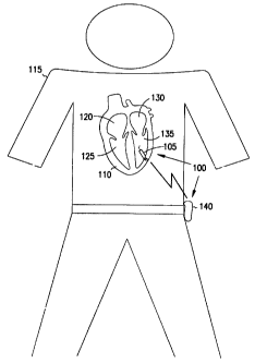
Figure 1 is a schematic diagram illustrating generally one embodiment of
portions of a sensor system, such as a pressure monitor system, and an
environment in which it is used.
Figure 2 is a schematic diagram illustrating generally an embodiment of
certain external portions of the system.
Figure 3A is a schematic/block diagram illustrating generally one
embodiment of a portion of an implantable sensor device, such as an
implantable
pressure monitor device including a corkscrew stabilizer.
Figure 3B is a schematic/block diagram illustrating generally one
embodiment of an implantable sensor device, such as an implantable pressure
monitor device including a harpoon or barbed stabilizer.
Figure 3C is a schematic/block diagram illustrating generally one
embodiment of an implantable sensor device, such as an implantable pressure
monitor device including a mesh stabilizer and a corkscrew stabilizer.
CA 02345389 2001-03-23
WO 00/16686 PCT/US99/20464
9
Figure 3D is a schematic/block diagram illustrating generally one
embodiment of an implantable sensor device, such as an implantable pressure
monitor device including a deformable stabilizer.
Figure 4 is a schematic diagram illustrating generally one embodiment of
the present system using wireless communication, such as intracorporeal
conductive communication, between an implanted medical device, such as
cardiac rhythm management system, and an external remote receiver.
Figure 5 is a schematic diagram illustrating generally one embodiment of
the present system using wireless communication, such as intracorporeal
conductive communication, between an implanted sensor device and an
implanted remote receiver that is carried by an implanted medical device such
as
by cardiac rhythm management system
Figure 6 is a cross-sectional schematic diagram illustrating generally one
embodiment of a placement catheter for implanting a sensor device, such as an
implantable pressure monitor device.
Figure 7 is a schematic diagram illustrating another embodiment of an
implantable sensor device, such as a pressure monitor, having a housing that
is
substantially implanted within tissue, such as the interior wall of a heart
chamber.
Figure 8 is a schematic diagram illustrating generally another
embodiment of a sensor device for implantation substantially within tissue and
having a substantially flexible anchor.
Figure 9 is a schematic diagram illustrating generally another
embodiment of a sensor device for implantation substantially within tissue and
having a substantially rigid anchor.
Detailed Descrintion
In the following detailed description, reference is made to the
accompanying drawings which form a part hereof, and in which is shown by way
of illustration specific embodiments in which the invention may be practiced.
These embodiments are described in sufficient detail to enable those skilled
in
the art to practice the invention, and it is to be understood that the
embodiments
may be combined, or that other embodiments may be utilized and that
structural,
logical and electrical changes may be made without departing from the spirit
and
CA 02345389 2007-07-03
scope of the present invention. The following detailed description is,
therefore,
not to be taken in a limiting sense, and the scope of the present invention is
defined by the appended claims and their equivalents. In the drawings, like
numerals describe substantially similar components throughout the several
5 views.
This document describes, among other things, an implantable sensor,
such as a pressure monitor. The sensor device is implanted in a heart chamber
(or elsewhere) and wirelessly communicates information therefrom. In one
embodiment, the sensor device is capable of providing less invasive chronic
10 measurements of pressure, such as, by way of example, but not by way of
limitation, measurements of blood pressure in the left ventricle of the heart.
The
implantable pressure monitor reduces the risk of obtaining such important
measurements, enabling a physician to more accurately diagnose and treat
serious heart conditions.
System OverYiew
Figure 1 is a schematic diagram illustrating generally, by way of
example, but not by way of limitation, one embodiment of portions of a sensor
system, such as pressure monitor system 100, and one environment in which
system 100 is used. In Figure 1, system 100 includes a sensor device, such as
an
implantable pressure monitor device 105. Device 105 is introduced into a
living
organism, such as in a heart chamber or other organ or body cavity. Miniature
implantable device 105 is capable of measuring internal body pressure, such as
in humans or animals. Aspects of one embodiment of device 105 and its
operation are described in Brockway et al. U.S. Patent No. 4,846,191 entitled
"Device For Chronic Measurement of Internal Body Pressure," which is assigned
to the assignee of the present application.
In Figure 1, device 105 is implanted in a heart 110 of a human patient
115. Heart 110 includes several heart chambers, such as a right atrium 120, a
right ventricle 125, a left atrium 130, and a left ventricle 135. In this
particular
example, device 105 is implanted, using a placement catheter, inside left
ventricle 135 where it is stabilized, such as by securing the device 105 to an
interior wall of left ventricle 135. However, in other embodiments, device 105
is
CA 02345389 2001-03-23
WO 00/16686 PCT/US99/20464
11
implanted in one of the right atrium 120, right ventricle 125, left atrium
130, or
within other organs or body cavities. Device 105 can be introduced into the
body translumenally (e.g., transvenously or transarterially), endoscopically,
laparoscopically, or otherwise (e.g., during open heart surgery).
In this embodiment, system 100 also includes an implantable or external
receiver 140 or other receiver, transceiver, transponder, or communication
device. Device 105 wirelessly communicates pressure information from the
organ in which device 105 is located, such as by using radio telemetry or any
other wireless communication technique. In Figure 1, left ventricular blood
pressure information is communicated by device 105 and received by an external
receiver 140 worn by the patient. In one embodiment, receiver 140 includes a
memory or recording device for storing the pressure information received from
device 105. In a further embodiment, receiver 140 includes a real time clock
for
time-stamping the pressure information with the time at which the information
is
received at receiver 140.
Figure 2 is a schematic diagram illustrating generally, by way of
example, but not by way of limitation, another embodiment of portions of
system 100. In Figure 2, pressure information that was stored in the memory or
recording device of receiver 140 is transferred into computer 200, such as via
an
electrical coupling cable 205, or alternatively via optical communication, or
using any other wired or wireless communication technique. In one
embodiment, computer 200 includes a processor for performing statistical or
other signal processing or analysis of the pressure information. In another
embodiment, computer 200 includes a display 202 for allowing the physician or
other care giver to review and analyze the pressure data. In one example,
display
202 includes diagnostic indicators based on analysis of the pressure data by
computer 200. In a further embodiment, computer 200 includes a memory for
archival of raw or processed pressure information. For example, the pressure
information can be electronically appended to the patient's medical record in
a
computer database.
Impla_ntable Pressure Monitor
Figure 3A is a schematic/block diagram illustrating generally, by way of
example, but not by way of limitation, one embodiment of device 105. In this
CA 02345389 2001-03-23
WO 00/16686 PCT/US99/20464
12
embodiment, device 105 includes a housing 300 carrying a sensor, such as
pressure transducer 305, and a communication circuit 310. Housing 300 is
adapted for implantation in a living organism such as a human or animal. In
one
example, housing 300 is implanted within a body cavity or an organ, such as
within a heart chamber (e.g., left ventricle 135) of heart 110.
In one embodiment, device 105 includes a stabilizer 312A extending
outward from housing 300 to stabilize or secure device 105 at a particular
location in the heart chamber or other organ in which device 105 is implanted.
Figure 3A illustrates a corkscrew stabilizer 312A which, in one embodiment,
includes a solid coiled needle extending longitudinally outward from housing
300. By rotating device 105, corkscrew stabilizer 312A is screwed into the
wall
of the heart chamber or other organ in which device 105 is disposed, thereby
securing device 105 at a particular location in the body. The corkscrew
stabilizer
312A is used with or without one or more barbs. The barbs are located, for
example, at a tip distal from device 105, or at different locations along the
helical
length of stabilizer 312A. In one embodiment, the surface of corkscrew
stabilizer 312A is coated or otherwise prepared to promote the growth of
fibrotic
tissue to reliably secure device 105 to the heart wall or other desired
location.
Figure 3B illustrates generally one embodiment of a harpoon stabilizer
312B, providing an approximately straight outward extension from housing 300,
and including a barb or hook at its distal tip. Figure 3C illustrates
generally one
embodiment of a mesh stabilizer 312C, extending outward from or integrally
formed with housing 300. Mesh stabilizer 312C also promotes the ingrowth of
adjacent fibrous tissue to assist in securing device 105 at a particular
location.
Figure 3D illustrates generally one embodiment of a flexible or expanding
deformable stabilizer 312D. In one embodiment, stabilizer 312D is made of a
flexible, spring-like, or deformable material or a "memory metal." As
illustrated
in Figure 3D, stabilizer 312D maintains a compact shape during implantation,
but deforms or expands in profile after device 105 is implanted into the heart
chamber or other body cavity. As a result of this deformation or expansion,
stabilizer 312D tends to hold device 105 within the body cavity in which it is
implanted. The above-discussed stabilizers 312 can also be used in combination
with each other, such as illustrated in Figure 3C.
CA 02345389 2001-03-23
WO 00/16686 PCT/US99/20464
13
Figures 3A - 3D illustrate particular embodiments of device 105 in which
the internal pressure of the organ is provided to pressure transducer 305 via
a
pressure communication apparatus such as, by way of example, but not by way
of limitation, a flexible or rigid pressure transmitting catheter (PTC) 315.
In one
embodiment, pressure transmitting catheter 315 senses a pressure at one or
more
pressure-sensitive mechanisms (e.g., a diaphragm, gel-like cap, or other
compliant structure) at its distal tip 320. Pressure transmitting catheter 315
comrnunicates the pressure, via a bore, shaft, or lumen 325, to its proximal
end
330 that interfaces with transducer 305. Lumen 325 extends substantially
between distal tip 320 and proximal end 330 of pressure transmitting catheter
315. In one embodiment, lumen 325 is filled with a pressure-transmitting
medium, such as a fluid of.any viscosity, a gel-like material, a combination
of
fluid and gel-like material, or any other flowable medium. In one embodiment,
by way of example, but not by way of limitation, distal tip 320 includes a
biocompatible and pressure-transmitting gel cap for transmitting substantially
steady-state and/or very low frequency pressure variations, and distal tip 320
also includes a thin-wall compliant structure for transmitting pressure
variations
at higher frequencies. Lumen 325 is filled with a pressure-transmitting fluid
retained within lumen 325 by the gel cap. The gel cap also prevents body
fluids
from entering lumen 325. Similarly, in one embodiment, proximal end 330
includes one or more pressure-transmitting mechanisms (e.g., a diaphragm, gel-
like cap, or other compliant structure), which also retains the pressure-
transmitting fluid in lumen 325. Although one embodiment of device 105
includes pressure transmitting catheter 315, the technique of communicating
pressure to pressure transducer 305 is not limited to using pressure
transmitting
catheter 315. For example, device 105 alternatively provides a pressure
transmitting mechanism that is integrally formed with housing 300 of device
105
rather than extending outwardly therefrom. Other embodiments of device 105
include the use of any other technique of receiving pressure at pressure
transducer 305.
Pressure transducer 305 receives the pressure communicated by pressure
transmitting catheter 315, or by any other pressure communication mechanism,
at the interface at its proximal end 330. In response, pressure transducer 305
CA 02345389 2001-03-23
WO 00/16686 PCTIUS99/20464
14
provides an electrical pressure signal that includes pressure information,
such as
steady-state pressure or variations in pressure. In one embodiment, pressure
transducer 305 includes a semiconductor resistive strain gauge, the resistance
of
which varies according to the pressure communicated by pressure transmitting
catheter 315. Transducer 305 is electrically coupled to communication circuit
310 and provides the electrical pressure signal to communication circuit 310.
Communication T , n'4ues
Communication circuit 310 wirelessly transmits pressure information
from device 105 to remote receiver 140 (or other receiver, transceiver,
transponder, or communication device) by radio telemetry or any other wireless
data communication technique. In one embodiment, communication circuit 310
includes or is coupled to an antenna for wireless communication. However, the
antenna need not be located within communication circuit 310. In another
embodiment, communication circuit 310 also includes signal processing
circuits,
such as amplification and filtering circuits that process the electrical
pressure
signal received from pressure transducer 305, or analog-to-digital conversion
circuits, or a microprocessor or other circuit for performing data analysis or
data
compression. In a further embodiment, communication circuit 310 also includes
a memory device for storing the pressure information, other data, or operating
parameters of device 105. In yet another embodiment, communication circuit
310 includes a real-time clock for time-stamping the pressure information.
In one embodiment, at least one of communication circuit 310 or
transducer 305 is powered by an internal power source such as a lithium or
other
suitable battery 335. In another embodiment, communication circuit 310 is a
passive transponder that is not powered by an internal power source. Instead,
communication circuit 310 receives energy wirelessly from a remote source,
such as an energy source external to the body of the patient in which device
105
is implanted. Communication circuit 310 is powered by the energy that it
receives wirelessly from the external source. In another embodiment, battery
335 is rechargeable and device 105 includes an energy reception circuit that
is
coupled to battery 335. The energy reception circuit in device 105 wirelessly
receives energy from a remote source, such as an energy source that is
external
to the body of the patient in which device 105 is implanted. The energy that
is
CA 02345389 2001-03-23
o- WO 00/16686 PCT/US99/20464
received by the energy reception circuit in device 105 is used by the energy
reception circuit to recharge battery 335.
In one example of passive transponder technology, communication
circuit 310 includes a first inductance, such as a coil. A second inductance,
such
5 as a coil, is placed outside the body, for example, at a location that is
close to the
site of the implanted device. The first and second inductances are inductively
coupled for wireless energy transmission from the external second inductance
to
the implanted first inductance, and for wireless data communication from the
implanted first inductance to the external second inductance. System 100 may
10 incorporate other passive transponder techniques as well.
In one embodiment, communication circuit 310 wirelessly communicates
pressure information from device 105 to external remote receiver 140 using an
intracorporeal conductive communication device (also referred to as "near-
field
intrabody communication" or a "personal area network"). In this document,
15 wireless communication refers to any communication technique that does not
use
a wire or optical fiber. Wireless conununication includes either or both of
unidirectional and/or bidirectional communication. The unidirectional or
bidirectional communication is carried out between any combination of
implanted and/or external communication devices. In various embodiments,
certain ones of the communication devices are carried by implanted sensor
devices (such as an implanted pressure monitor), implanted medical devices
(such as an implanted cardiac rhythm management device), and external
communication devices for communication therebetween. Wireless
communication includes, but is not limited to: radio telemetry, reactive
coupling, and intracorporeal conductive communication. In this document,
intracorporeal conductive communication refers to any communication technique
that uses a living organism (e.g., the body of a human or animal) as a
coiiductor
for communicating data. In one embodiment, wireless communication is used to
program operating parameters in implanted device 105.
In one example of an intracorporeal conductive communication device,
communication circuit 310 is electrically coupled to electrodes located on
housing 300 and insulated from each other. Communication circuit 310
capacitively couples a very low (e.g., less than a stimulation threshold of
heart
CA 02345389 2007-07-03
16
110) displacement current that is conducted through the body to remote
receiver
140. The current is modulated with a data signal. The data signal includes the
pressure information or other data to be wirelessly communicated from the
implanted medical device 105. In this embodiment, the resulting current is
detected at remote receiver 140 by electrodes that contact the body of patient
115
during the wireless communication from device 105. The detected current is
demodulated to obtain the pressure information or other data. The use of
intracorporeal conductive communication techniques is described in
Coppersmith et al. U.S. Patent No. 5,796,827 entitled "System and Method for
Near-Field Human-Body Coupling For Encrypted Communication With
Identification Cards," and in T.G. Zimmerman, "Personal Area Networks: Near-
field intrabody communication," IBM Systems Journal, Vol. 35, No. 3 & 4,
1996.
In one embodiment, system 100 includes, among other things,
communicating information from any implanted medical device to an external
remote receiver 140 using intracorporeal conductive communication (i.e., using
the body as a conductor). Examples of such implanted medical devices include,
but are not limited to: pressure monitors, cardiac pacemakers, defibrillators,
drug-delivery devices, and cardiac rhythm management devices.
Figure 4 is a schematic diagram illustrating generally, by way of
example, but not by way of limitation, one embodiment of system 100 using
either unidirectional or bidirectional intracorporeal conductive communication
between an implanted medical device, such as cardiac rhythm management
device 400, and an external remote receiver 140. This includes, for example,
intracorporeal conductive communication of data from electrodes 405A-B at the
cardiac rhythm management device 400 to electrodes 410A-B at the external
remote receiver 140, as well as programming operating parameters of cardiac
rhythm management device 400 based on instructions received via intracorporeal
conductive communication from external remote receiver 140.
Figure 5 is a schematic diagram illustrating generally, by way of
example, but not by way of limitation, another embodiment of system 100 using
either unidirectional or bidirectional intracorporeal conductive communication
between electrodes 505A-B at pressure monitor device 105, which is implanted
CA 02345389 2001-03-23
WO 00/16686 PCT/US99/20464
17
in left ventricle 135, and electrodes 405A-B coupled to an implanted remote
receiver 140 carried by an implanted medical device, such as by cardiac rhythm
management device 400. In one embodiment, cardiac rhythm management
device 400 includes a therapy generator that is coupled to heart 110 through a
leadwire. In this embodiment, device 105 senses left ventricular blood
pressure
and communicates, via intracorporeal conductive communication, left
ventricular
blood pressure information to cardiac rhythm management device 400 where it is
received by implanted receiver 140. Based on the received pressure
information,
cardiac rhythm management device 400 adjusts therapy delivered to heart 110.
In one example, cardiac rhythm management device 400 is a pacer or
pacer/defibrillator that adjusts the rate of delivering electrical pacing
pulses to
heart 110 via leadwire 500 based on the left ventricular pressure information
received from device 105. In another example, cardiac rhythm management
device 400 is a defibrillator or pacer/defibrillator that delivers
antitachyarrhythmia therapy to heart 110 based on the left ventricular
pressure
information received from device 105. Similarly, system 100 includes using
intracorporeal conductive communication to transmit information to device 105
from another implanted medical device, such as cardiac rhythm management
device 400. Moreover, the embodiments described with respect to Figures 4 and
5 can be combined for communication between any of one or more implanted
medical devices, one or more implanted sensor devices such as device 105,
and/or one or more external or implanted remote receivers 140.
Implantation and Jse
Figure 6 is a cross-sectional schematic diagram illustrating generally, by
way of example, but not by way of limitation, one embodiment of a placement
catheter 600 for implantably disposing device 105 in a heart chamber, such as
left ventricle 135. Catheter 600 includes an at least partially flexible
elongate
member having a proximal end 600A that is manipulated by the user. Catheter
600 also includes a distal end 600B of the elongate member that is inserted in
the
patient 115. In one embodiment, the distal end 600B of catheter 600 includes a
cavity 605 carrying at least a portion of device 105. Cavity 605 is
circumferentially encompassed by a sheath 607 that, in one embodiment, is open
at distal end 600B of catheter 600.
CA 02345389 2001-03-23
WO 00/16686 PCT/US99/20464
18
Catheter 600 also includes at least one engaging member, such as plunger
610. Plunger 610 engages device 105. In one example, an inner surface of
plunger 610 includes protrusions, such as pins 615, that engage receptacles
620
or other indentations in housing 300 of device 105. Plunger 610 is controlled
at
proximal end 600A of catheter 600 by a manipulator, such as handle 625.
Handle 625 is coupled to plunger 610 by a coupling member 630, such as one or
more rods or cables extending longitudinally within catheter 600. Plunger 610
is
capable of longitudinal motion toward and away from distal end 600B of
catheter 600, so that device 105 can be advanced from or retracted toward
cavity
605. Plunger 610 is also capable of rotational motion, by manipulating handle
625, so that corkscrew stabilizer 312A can be rotatably screwed into tissue
such
as the heart wall. Pins 615 engage receptacles 620 to ensure that device 105
rotates together with plunger 610.
In one embodiment, catheter 600 also includes a safety tether 635, which
is looped through an opening or other feature in housing 300 of device 105.
Tether 635 extends longitudinally through catheter 600 toward proximal end
600A, where the looped tether 635 is knotted or otherwise secured at a tether
keep 640 on handle 625 or elsewhere. Tether 635 secures device 105 to catheter
600 until final release of device 105 is desired, at which time tether 635 is
cut.
In another embodiment, catheter 600 includes a convex cap 640 at distal
end 600B. Convex cap 640 eases the translumenal travel of catheter 600 through
a blood vessel or other constriction. In one example, cap 640 is hinged to
catheter 600, such as at sheath 607, so that cap 640 opens outwardly from
distal
end 600B when device 105 is pushed out of cavity 605. In another example, cap
640 includes one or more deformable flaps that similarly open outwardly to
allow device 105 to be advanced out from cavity 605 by pushing device 105
against cap 640. In a further embodiment, cap 640 includes a material that is
soluble in body fluids after a predetermined time period. In this embodiment,
cap 640 dissolves after catheter 600 is translumenally guided to left
ventricle 135
or other desired location. After cap 640 dissolves, device 105 is advanced
longitudinally outward from cavity 605 at distal end 600B of catheter 600. In
another embodiment of the invention, cap 640 is omitted such that cavity 605
is
open to distal end 600B of catheter 600 even during translumenal insertion.
CA 02345389 2001-03-23
WO 00/16686 PCTIUS99/20464
19
In one example, catheter 600 is used to place device 105 in a heart
chamber, such as left ventricle 135. One such technique includes inserting
catheter 600 into the patient 115, such as via the subclavian artery. Catheter
600
is translumenally guided through the artery, through the left atrium, and
through
the mitral valve until its distal end 600B is within left ventricle 135.
Progress of
the catheter 600, as it travels from the insertion point to the left ventricle
135, is
typically monitored on a display using fluoroscopy. This assists the physician
in
translumenally steering catheter 600 along the proper path to a desired
location
in left ventricle 135. In the embodiment of device 105 illustrated in Figure
3A,
which includes a corkscrew stabilizer 312A, sheath 607 and/or cap 640 prevents
the sharp tip of corkscrew stabilizer 312A from damaging the blood vessel
while
device 105 is being translumenally maneuvered through the blood vessel.
In one embodiment, placement catheter 600 has high torsional stability
and is steerable. In this embodiment, sheath 607 and portions of catheter 600
near its distal end 600B are substantially rigid. Catheter 600 is adapted for
receiving, at its proximal end 600A, a removable stylet that extends
longitudinally along catheter 600. The stylet extends approximately to (or
slightly beyond) a distal end of coupling member 630. A straight stylet is
typically employed until distal end 600B of catheter 600 enters heart 110.
Then,
the straight stylet is removed from catheter 600 and a stylet having a curved
or
bent distal end is inserted in its place. By rotating the bent stylet as
catheter 600
is advanced into heart 110, the distal end 600B of catheter 600 is directed to
the
desired location in left ventricle 135 or other heart chamber.
When device 105 is positioned at a desired location in left ventricle 135,
plunger 610 is advanced slightly so that corkscrew stabilizer 312A protrudes
outwardly from cavity 605 and contacts the heart wall in the interior of left
ventricle 135. Handle 625 is rotated which, in turn, rotates plunger 610
together
with device 105, such that corkscrew stabilizer 312A is screwed into the heart
wall to secure device 105 in position (e.g., at the apex of left ventricle 135
or
other desired location). After securing device 105, plunger 610 is advanced
further. Plunger 610 is designed to open outwardly when it is extended outside
of sheath 607. As a result, pins 615 disengage from receptacles 620, releasing
the grip of plunger 610 on device 105. Tether 635 is then cut (at proximal end
CA 02345389 2001-03-23
WO 00/16686 PCT/US99/20464
600A of catheter 600) and removed, thereby releasing device 105. Catheter 600
is then withdrawn from the subclavian artery.
Figure 7 is a schematic diagram illustrating generally, by way of
example, but not by way of limitation, another embodiment of device 105 and an
5 environment in which it is used. In Figure 7, housing 300 of device 105 is
substantially implanted within the myocardium at the interior wall of left
ventricle 135 of heart 110. The pressure transmitting catheter 315 portion of
device 105 extends outwardly from housing 300 into left ventricle 135 for
sensing blood pressure its distal tip 320. In this embodiment, deformable
10 stabilizer 312D is integrated with a sharpened end of housing 300 so that
housing 300 can be advanced into the heart wall. Then, the deformable
stabilizer
312D is expanded in a spring-like fashion to secure device 105 at the desired
location. Device 105 is implanted using a placement catheter 600 as described
with respect to Figure 6. In one embodiment, housing 300 is designed to
15 promote fibrous ingrowth, such as by properly preparing housing 300 with a
coating and/or surface roughening, or by incorporating a mesh or fabric into
the
outer surface of housing 300.
Figure 8 is a schematic diagram illustrating generally, by way of
example, but not by way of limitation, another embodiment of device 105 that
is
20 capable of being implanted substantially within the interior wall of left
ventricle
135 of heart 110. In this embodiment, device 105 includes a helical anchor 800
surrounding a portion of device 105. In one embodiment, anchor 800 includes a
highly elastic metal such as, for example, a memory metal such as nitinol. A
spring constant of anchor 800 is low enough to allow anchor 800 to conform to
housing 300 of device 105 while torsional force is being applied to insert
device
105 into the myocardial tissue 805 or other tissue. Upon release of this
torsional
force, anchor 800 deforms, such as, for example, by returning to its original
shape. This results in the application of force to the surrounding myocardial
tissue 805 for securing a portion of device 105 to the tissue. In one
embodiment,
more than one anchor 800 is included such as, for example, an anchor 800 at
both proximal end 300A and distal end 300B of housing 300 of device 105. In
another embodiment, housing 300 of device 105 includes a head 810 portion at
proximal end 300A. Head 810 limits the advance of device 105 within
CA 02345389 2001-03-23
~
WO 00/16686 PCT/US99/20464
21
myocardial tissue 805. This ensures that device 105 has access to the left
ventricle 135 or other heart chamber to allow accurate blood pressure
measurements in the heart chamber. This also reduces the risk of fibrous
tissue
growing over the pressure-sensitive portion of device 105, such as pressure
transmitting catheter 315.
Figure 9 is a schematic diagram illustrating generally, by way of
example, but not by way of limitation, another embodiment of device 105 that
is
capable of being implanted substantially within myocardial tissue 805. In this
embodiment, device 105 includes a substantially rigid helical metal coil
(e.g., a
titanium coil) anchor 800 surrounding a portion of housing 300 of device 105.
Anchor 800 has a profile similar to that of device 105, as illustrated in
Figure 9.
Upon application of a torsional force, anchor 800 screws into the heart wall.
In
another embodiment, more than one anchor 800 is included such as, for example,
an anchor 800 at both proximal end 800A and distal end 800B.
(~~rsl u ion
The present system includes, among other things, a sensor device such as
a pressure monitor. The sensor device is implantable in a heart chamber or
elsewhere, and it wirelessly communicates sensor information therefrom. In one
embodiment, an implantable pressure monitor provides less invasive chronic
measurements of pressure, such as, by way of example, but not by way of
limitation, measurements of left ventricular blood pressure. The implantable
pressure monitor reduces the risk of obtaining such important measurements,
enabling a physician to more accurately diagnose and treat serious heart
conditions.
Though particular aspects of the system have been described in
conjunction with its use in measuring left ventricular blood pressure, it is
understood that the system can also be used for measuring pressure elsewhere.
For example, but not by way of limitation, the system can also be used for
measuring pressure in other heart chambers, blood vessels (e.g., pulmonary
artery), body organs (e.g., the bladder, kidney, uterus), or body cavities
(e.g., for
intracranial, intraocular, or intrapleural pressure measurements). Moreover,
though translumenal implantation has been described using a placement
catheter,
the present system also includes implantation using an endoscope, laparoscope,
CA 02345389 2001-03-23
WO 00/16686 FCT/US99/20464
22
or other minimally invasive or other surgical technique. In one example, the
implantable sensor device is directed into a urinary bladder via the urethra.
In
one such embodiment, the implantable sensor device includes a stabilizer or
other structure that expands following disposition in the bladder. As a
result, the
implantable sensor device is retained in the bladder without blocking flow to
the
urethra.
Though particular aspects of the system have been described in
conjunction with its use in measuring pressure, it is understood that the
system
can also be used with an implantable sensor for sensing manifestations of
other
physical parameters such as, by way of example, but not by way of limitation,
sensing blood gasses or other gasses (e.g., O2, COZ), pH, electrocardiograms,
and
blood glucose. In another example, the system is tised in conjunction with
ultrasonic measurements (e.g., measuring blood flow, or measuring heart wall
thickness for determining contractility, etc.).
It is to be understood that the above description is intended to be
illustrative, and not restrictive. Many other embodiments will be apparent to
those of skill in the art upon reviewing the above description. The scope of
the
invention should, therefore, be determined with reference to the appended
claims, along with the full scope of equivalents to which such claims are
entitled.