Note: Descriptions are shown in the official language in which they were submitted.
CA 02347760 2001-04-19
WO 00/24131 PCTNS99/24868
1 POSITIONAL CAMERA AND GYS DATA INTERCHANGE DEVICE
FIELD OF THE INVENTION
The invention relates generally to a system for communicating data including
global-positioning-encoded information. In particular, the present invention
relates specifically
to a device and system for communicating and retrieving position and position
related data.
BACKGROUND OF THE INVENTION
Availability of up-to-date information is more important today than ever
before and this
will continue to be true for the foreseeable future. People want to be well
informed, so much so
that they travel with cellular phones, beepers, and even portable hand-held
Global Positioning
System (GPS) satellite receivers.
GPS capable devices generally have a GPS receiver for receiving satellite
signals from the
GPS satellite network that allow far determination of the device's position.
Such devices allow
for precisely locating the device in terms of latitude and longitude using the
GPS receiver. Some
devices have map data stored in memory and a display for showing the device
position with
reference to the map data. Other devices have no underlying map data base for
reference.
Rather, they show only the geographic coordinates of the device's location.
These coordinates
may be referred to as waypoints. Most GPS receiver devices can store many
waypoints. Some
GPS receiver devices can plot and display a trail of waypoints and store this
trail for future
retrieval. Sophisticated devices may compute the device's heading, speed, and
other information
based on comparisons with previous GPS determined positions.
GPS receiver devices with map display capability may store the map information
on
computer diskettes, CD-ROM's, or other computer memory storage devices. The
device location
may then be displayed on a display terminal with reference to a map stored in
the computer
memory storage device. The available quantity of map data, however, can
overwhelm the
memory capability of easily portable computer devices. This problem is
exacerbated when
additional information is included and linked with the map data. In addition,
information is more
valuable when it is up to date and available at the time of consumption, and
such devices do not
incorporate a means for updating the stored information. By way of example, a
CD ROM could
never maintain an up-to-date list of every 5-star restaurant.
Some GPS receiver devices have the ability to communicate over a
telecommunications
network. These devices do not provide for automatic or semi-automatic dynamic
exchange of
on-line position dependent or related information. In addition, these devices
cannot communicate
with third parties in the absence of a uniform data format standard. For
example, a
cellular-phone-based system comprising GPS location information working in
conjunction with
proprietary Public Safety Answering Point (PSAP) telephone equipment is known.
The device
provides personal and medical information on an emergency basis to the proper
authorities. Such
_1_
CA 02347760 2001-04-19
WO 00/24131 PCT/US99/24868
1 a device does not allow third parties to communicate, tag, interrogate,
limit, designate, modify
or share this information amongst themselves for any other use.
To that end, the ability to receive digital data structures with GPS encoding,
and storing
this information for eventual use or broadcast to third parties, would be
valuable. Today, the U.S.
and several other countries have independent publishers busily GPS mapping
everything down
to the most minute detail. Most of these data bases are available on CD ROM
storage. The
problem is that no one data base can contain enough information to fulfill the
unique requests of
every particular and picky consumer. The costs associated with providing and
maintaining such
a large data base would be overwhelming and over-burdening. Additionally, most
consumers do
not like reading or compiling vast data bases.
SUMMARY OF THE INVENTION
The system of the present invention utilizes Personal Communications Devices
(PCDs),
and traditional computer systems with GPS engines, routers, and other
application programs to
1 S request, process, and transmit tagged GPS encoded information. The system,
with related
applications, can be accessed by device users, traditional computer users, web-
site users
(cyberspace), data publishers, public or private enterprises or individuals,
by means of application
programs. The tagged GPS encoded data files can be stored or sent via
communication links
using AM, FM, spread spectrum, microwave, laser or light beam in -free or
fiber optic,
line-of sight, reflected, satellite, secure or non-secure, or any type of
communications between
multiple points that the application or the state-of the-art may allow. The
system is a waypoint
tag and interrogation system using various protocols to answer requests and
provide
GPS-encoded information. The applications use GPS devices, engines, routing
and encoding for
access to specific requester-designated data retrieval requests. The
applications access fax
machines, beepers, telephones and other communication linked devices. The
system accesses
computer and storage systems with various applications in order to provide
this information from
a plurality of providers. The system thereby eliminates or reduces the need
for large storage
devices and interchangeable storage modules.
One embodiment of the present invention includes a requesting device, a data
provider
(hardware and software), a user, tagger applications or GPS engine and muter
system with
protocols for encoding, tagging, modifying, interrogating, arranging,
limiting, displaying, sorting,
mapping, segregating, sending, receiving and updating waypoint and the
waypoints connected
data structures with digital or graphic maps, digital voice files, linked
digital web files properly
encoded and tagged by way of specific devices, or by traditional computer and
storage systems.
3 S The application programs contain protocols for users, providers, taggers,
list maintenance
organizations, and others, and will use a dynamic identification system from
applications
containing GPS search engines, route planners, compilers, designators,
publishers, and others to
permit communication of information.
-2-
CA 02347760 2001-04-19
WO 00/24131 PCT/US99124868
1 The PCD is a cellular-phone-sized electronic device, combining the
capabilities of a GPS
receiver, transceiver, digital beeper, cell phone and projection system into
one compact unit. The
PCD is capable of uploading emergency information (medical, police alert,
etc.) via a one-push
button that phones 911 or a security monitoring center similar to those used
for house alarms.
The alert continues to be broadcast until a response is made.
The PCD is also capable of downloading information via a request to a data
provider,
similar to a request for directory information from a phone company or other
service. In this
mode the PCD acts similar to calling a phone operator for information.
However, in this
instance, no human contact is required. The caller requests specific
information (location of gas
stations, names of restaurants, local banks, etc.) via a voice command
("Download e.g., Wells
Fargo Banks") or via digital commands using. a keypad or other input device
and the requested
information is automatically downloaded to and stored in the memory of the
user's PCD. This
information can be accessed off line via the screen on the PCD. It is all done
digitally,
eliminating having to write down information such as name, address, location
map, GPS latitude
I 5 and longitude encoding, direction and distance to location, hours of
operation, or other items of
information. The PCD can be plugged into an automobile input port or similar
device, if
available, and provide distances and directions to locations of interest.
Similar information of
a condensed nature can also be provided to the user via the screen of the PCD.
The user is not
required to be a subscriber to some proprietary system, instead the PCD can
use any means to
access any data base from any potential provider, whether GPS encoded or not.
In some areas the information would be sent and received by way of a Local
Area
Broadcast via radio frequency signals to each home, car or PCD within a
reception area. In such
an embodiment, users are able to access companies listed on the broadcast
network from data
providers of properly tagged, yellow page-type information or are provided
with GPS encoded
information and maps similar to web page listings. This would be advantageous
to small towns
with little information available for travelers, but which have an interest in
providing up-to-date
traffic, weather and travel advisories to benefit the local community and
businesses. Such a
system does not require a master, home or base unit. The providers of data
base or advertising
information could be a single data provider and could also be individual users
with application
programs that allow provision of such data. The application programs provide a
means for
sending and receiving data, GPS encoded data and graphics encoded data. The
application
programs can also act as a universal coder/decoder to other proprietary GPS
data bases.
The present invention allows users to request detailed information relating to
their present
location as well as information related to distant locales. Some of the
advantages provided by
the invention include:
1. Information can be received digitally by a PCD user from any system.
2. Multiple requests can be retained, stored or resent.
3. In-depth dynamic data retrievals are possible and could be viewed later.
-3-
CA 02347760 2001-04-19
WO 00/24131 PCTNS99/24868
1 4. GPS tagging and encoding with latitude and longitude information along
with
encoded maps for navigation.
5. Small non-contiguous map segments are possible.
6. On-line storage of data personal and other information, along with GPS
encoded
maps on some data files.
7. Display menus, interfaces and applications can be viewed on heads-up
display
systems in automobiles, homes, businesses and various commercial applications.
8. Allows for portable Internet access.
9. Provides a means for an Internet based telephone directory access tagged
and
linked to the originating area code and phone numbers.
Remote and distant third parties could communicate with each other and, by
sending and
receiving GPS encoded data, can meet or find each other in remote locations.
Maps and other
digital data may be transmitted/received by fax, beeper (receive only),
computer, phone and
radio.
The system also utilizes a system of non-subscribers communicating to each
other in a
similar fashion, without the use of base stations. In addition, the non-
subscribers could send
personal data bases with maps included, GPS information, and other information
of non-related
data or graphics from publishers of any such data base. In this embodiment the
device would act
as a transceiver, sending and receiving dynamic moving waypoint information in
digital formats,
including maps of various sizes and embodiments.
The PCD can display a singular or a plurality of images and displays, project
an image
on to a screen or viewing surface, store or communicate data (depicted as a
line, graphic, icon,
etc.) to and/or receive latitude and longitude data from third parties.
Additionally, the device can
send/receive latitude- and longitude-encoded maps and other data to/from a
third party,
send/receive standard or non-standard phone and fax communications (AM, FM,
spread
spectrum, microwave, laser or light beam in free or fiber optic, line of
sight, reflected, satellite,
secure or non-secure, or any type of communications between two points that
the application or
state-of the-art may allow), perform computer functions from existing
application software and
operating systems, receive standard or non-standard beeper messages, interface
with a
3 0 conventional computer and provide an interface to a heads-up display, an
external viewing device
or any projection system.
An embodiment of this invention incorporates a GPS transceiver with a
designated
application used with a communication system or network. Several users can
communicate and
send data, maps and graphic files with or without GPS encoding. By example, a
user could
~35 request from sensing, weather, or condition reporting devices details
concerning remote
locations. These sensing, weather, and condition reporting devices may also be
accessible over
cable land lines or other communication media.
-4-
CA 02347760 2001-04-19
WO OO/Z4131 PCT/US99/24868
1 In one embodiment of the device and tagging system information is
communicated from
locations, homes, businesses, commercial designations, government resources,
public and private
areas, cyberspace and other communication systems. Various designated
locations, or a plurality
and multiplicity of locations, or data structures, are assigned as waypoints.
These waypoints
could be tagged, or interrogated from an application program which describes,
encodes, reports,
modifies and communicates this encoded information and data from any location.
In addition,
the transmitting device may report a plurality and multiplicity of locations
or events unrelated to
either the location of either the transmitting or receiving device. Indeed,
the device could
communicate to many unlinked, unreported or unconnected waypoints and send
active dynamic
information to the requester. Cyberspace providers may enter the network web
system, use
applications for device communications and .participate in the exchange of
information using
designated GPS engines and applications. By way of example, the invention can
provide a
requester with dynamic location information, or other data to a location
anywhere in the U.S.
This location information may be used to locate individuals in determining
whether to authorize
credit requests, whether PCD or item containing a PCD, such as an automobile,
is moved, or in
routing electronic communications.
The system is similar to the world wide web, except the web does not use GPS
engines,
applications, tagging systems, etc. By way of example, one difference is that
the invention uses
GPS devices, engines, applications and encoding for access to specific
requester designated data
retrieval techniques. Indeed, the invention provides a means to locate
specific individuals both
physically and in terms of an electronically accessible location.
Another advantage the invention provides is a means to display this type of
information and a means to store data unrelated to any interrogation by the
PCD device. Methods
of display include multiple of displays including, by example, overhead
displays, heads-up
displays, projection systems, LCD displays, computer displays or any past or
future designed
displays whether connected directly or by some electromagnetic means. The
preferred
embodiment of the device could include any means of display or combinations
thereof. In
addition, the device could include many control devices such as remote
control, remote mouse
type devices and any combination of keyboards.
Further objects, features and advantages of the invention will become apparent
from the
following detailed description taken in conjunction with the accompanying
drawings showing
an illustrative embodiment of the invention in which like parts are designated
by like reference
numerals throughout.
-5-
CA 02347760 2001-04-19
WO 00/24131 PCTNS99/Z4868
1 DESCRIPTION OF THE DRAWINGS
FIG. 1 illustrates a GPS transceiver system and communication links
incorporating the
present invention;
FIG. 2 is a front perspective view of a PCD of the present invention showing a
layout of
controls and an initialization screen;
FIG. 3 is a rear view of the PCD of FIG. 2;
FIG. 4 is a block diagram of the PCD of FIG. 2;
FIG. 4A shows a screen menu hierarchy of the PCD of FIG. 2;
FIG. SA illustrates a flow chart depicting the program sequence for the entry
of a personal
identification number (PIN) and personal data into the PCD of FIG. 2
FIG. SB illustrates a flow chart depicting the program sequence for the user
to select a
mode of operation using the PCD of FIG. 2;
FIG. 5 C illustrates a flow chart depicting the program sequence for the user
to control the
GPS mode of the PCD of FIG. 2;
FIG. SD illustrates a flow chart depicting the program sequence for the user
to control the
phone mode of the PCD of FIG. 2;
FIG. SE illustrates a flow chart depicting the program sequence for the user
to control the
computer mode of the PCD of FIG. 2;
FIG. SF illustrates a flow chart depicting the program sequence for the user
to control the
radio mode of the PCD of FIG. 2;
FIG. b illustrates the Main Menu page of the PCD of FIG. 2;
FIG. 7 illustrates the select GPS Function page of the PCD of FIG. 2;
FIG. 8 illustrates the GPS: Location page of the PCD of FIG. 2;
FIG. 9 illustrates the GPS: Show Me page of the PCD of FIG. 2;
FIG. 10 illustrates the GPS: Get Map page of the PCD of FIG. 2;
FIG. 11 illustrates the GPS: Third Party page of the PCD of FIG. 2;
FIG. 12 illustrates the FAX page of the PCD of FIG. 2;
FIG. 13 illustrates the Beeper page of the PCD of FIG. 2;
FIG. 14 illustrates the Phone page of the PCD of FIG. 2;
FIG. 15 illustrates an Information Request page of the PCD of FIG. 2;
FIG. 16 illustrates the Computer page of the PCD of FIG. 2;
FIG. 17 illustrates the Radio page of the PCD of FIG. 2;
FIG. 18 illustrates the Receive Queue page of the PCD of FIG. 2;
FIG. 19 illustrates the Send Queue page of the PCD of FIG. 2;
FIG. 20 illustrates a typical listing downloaded from a data provider;
FIG. 21 illustrates a typical GPS encoded map downloaded from a data provider;
FIG. 22 illustrates a typical GPS encoded map with waypoints locating
restaurants within
a specified radius;
-6-
CA 02347760 2001-04-19
WO OO/Z4131 PCTNS99124868
1 FIG. 23A illustrates an exemplary data provider;
FIG. 23B illustrates an exemplary configuration of a non-PCD computer
utilizing a
modified application module;
FIG. 24 illustrates a software module configuration of a requester;
FIG. 25 illustrates a software module configuration of a provider;
FIG. 26 illustrates a software module configuration of the application module;
FIG. 27 illustrates a software module configuration of the tagging system;
FIG. 28 illustrates a software module configuration of the GPS engine;
FIG. 29 illustrates a software module configuration of the universal
translator;
FIG. 30 illustrates a typical configuration of the service provider;
FIG. 31 illustrates a possible configuration of the digital web TV;
FIG. 32, illustrates the Weather Map Request page of the PCD of FIG. 2;
FIG. 33 illustrates a weather reporting device;
FIG. 34 illustrates a block diagram of the condition reporting device of the
present
invention;
FIG. 35 illustrates several condition reporting devices of FIG. 34 deployed
along an
arterial route;
FIG. 36 illustrates a block diagram of a cable television distribution system
for condition
reporting devices of the present invention;
FIG. 3 7 illustrates a process for using route information to obtain
information concerning
the availability of condition reporting devices;
FIG. 3 8 illustrates a PCD displaying a trail plot with condition reporting
device locations;
FIG. 39 illustrates a process of a manual method of obtaining condition
reporting device
information;
FIG. 40 illustrates a PCD display showing information received from a
condition
reporting device;
FIG. 41 illustrates a process of the automatic handoff method for obtaining
condition
reporting device information;
FIG. 42 illustrates a process of the automatic sequence method for obtaining
condition
reporting device information;
FIG. 43 illustrates a display of a PCD display showing a user's route
comprised of
multiple segments;
FIG. 44 illustrates a block diagram of a local area transmission system for
providing
multimedia information;
FIG. 45 illustrates a process of obtaining cell site based information;
FIG. 46 illustrates a process of credit authorization;
FIG. 47 illustrates a process of determining alternative route travel times.
FIG. 48A-H illustrate an alternate embodiment of a PCD of the present
invention; and
_7_
CA 02347760 2001-04-19
WO 00/24131 PCf/US99/24868
1 FIGs 49A-G illustrate the alternate embodiment of a PCD of FIGs 48A-H.
DETAILED DESCRIPTION OF THE INVENTION
FIG. 1 shows a system capable of communicating using the electromagnetic
energy
spectrum, traditional computer networks, cellular phone networks, public
telephone networks,
and satellite system networks. The major components of the system comprises
personal
communication devices (PCDs) 20 and one or more of the following: a cellular
phone network
60, a standard phone line network 70, an electromagnetic energy spectrum
network 80 and/or a
computer network 90. The PCD receives signals from a GPS satellite system 10.
FIG. 2 illustrates a PCD of the present invention. The PCD has a display 28a.
The
display may be of a LCD type or other types known in the art. Incorporated
with the display is
a touch screen input device 28b, which are known in the art. The PCD also has
a alphanumeric
key pad 26, which includes many of the standard keys generally found on
computer keyboards.
1 S The location of the keys, and the selection of the characters used on a
single key, may be varied
as desired. The PCD also has specialized keys 27a-g, n related to GPS,
telecommunications, and
other functions. Located on one side of the PCD are a number of input and
output ports. In the
embodiment shown, these ports include a modem output port 29g, a generalized
communication
port 29f, a power port 35b, an infrared port 29e, and a heads-up display
interface port 25k. The
location of these ports are shown for descriptive purposes only, the specific
location of these
ports on the PCD is not critical. The power port allows the PCD to be operated
from an external
power source (not shown). The communication port allows the PCD to be
connected to printers,
local computer networks, and the like.
FIG. 3 shows a rear view of the PCD of FIG. 2. The rear of the PCD contains a
microphone 34 towards one edge of the rear of the PCD and a speaker 33 towards
the opposing
edge. The layout of the microphone and the speaker is similar to that found in
portable cellular
telephones. An antenna 32 extends from the edge near the speaker to allow for
communication
in a cellular telephone network or via other electromagnetic spectrum means.
The PCD contains
a battery 38a. The battery allows for mobile operation of the PCD and is the
selected power
source if an external power source is not available through the power port.
The PCD's operation
is governed by a processor 21. A variety of microprocessors may be used, with
the selection of
such determined by processing power, power utilization, and other factors and
requirements. The
PCD has a slot 23 for a PCMCIA card, CD-ROM, or other computer accessory. The
PCD is
powered on when the power button 31 (shown in FIG. 2) is depressed. In the
embodiment
shown, at initial device power on, the processor causes the PCD to display the
initialization
screen 100 (shown in FIG. 2).
FIG. 4 shows a block diagram of the PCD. Control and logic functions are
performed by
the processor 21. Internal data storage 22, which is provided by conventional
memory such as
_g-
CA 02347760 2001-04-19
WO 80/24131 PCT/US99/Z4868
1 RAM or ROM or variations thereof, may be accessed by the processor. The
processor may also
access removable data storage devices 23 such as a hard disk installed via the
PCMCIA slot, a
CD-ROM type device or other similar removable data storage devices. The
processor is
connected by a data bus 24 to a number of devices. These include the
alphanumeric key pad and
other special purpose keys, the touch screen, and other hard wired input
devices. The heads-up
display output port and the display screen are also connected via the data bus
to the processor,
it being recognized that a number of display related devices such as VGA
cards, chips, and the
like are also required to implement the display device fiinctions and the
other previously
mentioned functions. The microprocessor may also access or control
communications with
telephone networks, either hardwired or cellular, radio transmissions, infra-
red transmissions, or
communications with other computer devices.
All known verbal commands from GPS systems can be implemented and attachment
or
inclusion of voice activation for map instructions relative to location, GPS
and street
designations, including heading descriptions, distance, and arrival time
estimates can be included.
FIG. 24 illustrates a block diagram of the PCD's software components. An
application
module or program 51 interfaces with the PCD's operating system 241. The
operating system
may be DOS, UNIX, Windows 95, Windows NT, O/S2 Apple Mclntosh, Next Computer,
or
other operating systems, including operating systems well suited to devices
with constrained
memory or other limitations due to the small physical size of the PCD. The
operating system
additionally interfaces with other application programs 242 that provide
standard file edit and
other functions typically found in personal computers. The operating system,
or other application
programs interfacing with the operating system, provide for maintenance of
data bases 245 used
by the PCD. The application module includes a GPS engine 53 providing GPS
functions,
including interfacing with the GPS receiver 243 (shown in FIG. 4). A query
menu program 54
of the application module controls the graphical user interface and related
functions for the
device. Included in the application module is a universal converter S5.
As illustrated in FIG. 29, the universal converter enables the PCD to read in
data provided
by third parties 291a, b and convert or filter such data to a format useable
by the PCD. The
universal converter first inspects the received data to determine if the data
is in a known format
which can be converted to the format used by the PCD. If the format is not
known by the device,
the universal converter attempts to extract any ASCII data or format the data
as a bit map as
appropriate.
As illustrated in FIG. 26, the application module further includes programs to
implement
data formatting and communication protocols using header protocols 271, layer
protocols 272,
3 5 and data provider protocols 273. The application module also includes a
tagging system interface
program 274. The elements of the tagging system are illustrated in FIG. 27.
The purpose of the
tagging system is to provide a common universal data structure for requests
and responding to
requests. Various techniques common in the GEO coding industry, using U.S.
Census bureau
-9-
CA 02347760 2001-04-19
WO 00/24131 PCT/IJS99/24868
I data and tiger files with certain modifications, can establish parameters
for software suppliers to
use latitude and longitude encoding as coordinate pairs, postal code encoding
and street centering
encoding, all for the benefit of accuracy in designating certain files as
"tagged". The tagging
system provides the ability to apply and strip header and layer information to
and from data files.
FIG. 4A shows the top level page menu display hierarchy of the PCD. At initial
power
on the initialization page 25a (shown in FIG. 2) is displayed. The
initialization page allows for
the entry of a personal identification number and other data. Depressing the
home button 27E
(shown in FIG. 2) displays the Main Menu page 25b. A number of additional
pages are available
from the Main Menu page. These include the GPS 25c, Fax 25d, Beeper 25e, Phone
25f,
Computer 25g, Radio 25h, Send Queue 25i, and Receive Queue 25j pages.
FIG. SA lists a sequence for the operator of the PCD to answer certain
questions, provide
information for future access regarding handling of emergency events and
handling of same by
civil authorities or private individuals empowered to act on behalf of the
operator. Access is
denied or provided based upon user codes. The entry of a user code may allow
for limited to full
access of the data stored in the device and usage of same with different codes
providing different
levels of access and usage. Similar information and sequencing is provided by
the application
modules and operating system for medical and other information in the event of
emergencies.
In one embodiment of the preferences screen .(not shown) information can be
displayed in a
specified manner, events recorded and equipment options listed. Specific usage
of the device and
furnished software would be recalled by each user having access and user codes
to operate the
PCD, each user having unique individual screens and setups based on that
user's preferences.
The initial setup of screen preferences and other user configuration details
are well known in
the art.
Selecting PIN 111 from the Main Menu page displays a screen 113 prompting the
user
to input a personal identification number. Using an alphanumeric key pad 26,
the user inputs a
personal identification number and presses ENTER 27g. The processor analyzes
the entered
personal identification number and determines if the number is valid I I 5
FIG. If the entered
personal identification number is valid the processor enables PERSONAL 121,
MEDICAL 13 l,
PREFERENCES 141 touch points on the display screen. These touchpoints, and
touchpoints
later referred to, are selectable either by pressing the display screen at the
touchpoint location or
by selecting the underlying display item with the cursor. If the PCD already
contains personal,
medical and preference data, the HOME button 27e is enabled. If the personal
identification
number is not valid, the processor 21 will increase the device security level
119. This may
include, but is not limited to, disabling the PCD operation for a specified
time. Selecting
PERSONAL 121, MEDICAL 131 or PREFERENCES 141 touchpoints displays the
corresponding pages 123, 133, or 143. These pages request specific data, and
allow the user to
input data using alphanumeric key pad 26. Completion of data entry is
indicated by pressing the
ENTER button 27g.
-10-
CA 02347760 2001-04-19
WO 00/24131 PCT/US99/24868
In addition, the Initialization page 100 F1G. 2, as well as all other pages,
displays the time
and the date 103, touch points for QUE IN 550 and OUT 600 (described later in
this document)
and limited GPS information 107. The limited GPS information comprises of the
user's location
(latitude and longitude), an arrow pointing to north and an arrow indicating
direction of device
travel.
When enabled, pressing the HOME button 27e (FIG. 2) signals the processor to
display
the Main Menu page 1 SO FIG. 5B. As shown in FIG. 6, the Main Menu page allows
the operator
to use the touch screen to select the GPS 200, FAX 300, BEEPER 350, PHONE 400,
COMPUTER 450, RADIO 500, RECEIVE QUE 550 and SEND QUE 600 touchpoints. The
heading and directional information are displayed in real time and are
dynamic. Pressing the
FAX touchpoint causes the processor to display a Fax page (shown in FIG. 12)
which lists
received facsimile messages 301. The Fax page includes display interfaces
appropriate for the
sending and receiving of facsimile communications through the FAX Phone Modem
port 29g,
and such displays and functions are well known in the art. Pressing the BEEPER
touchpoint
I S causes the processor to display a Beeper page (shown in FIG. 13). The
Beeper page displays
received beeper messages 3 S l and allows for the deletion of such messages
from the display and
internal memory storage. Also, a sub-menu portion of the display 1 S 1 is
reserved for sub-menus
and directories.
Pressing GPS 200 causes the processor 21 to display a GPS Function page 201,
which is
illustrated in FIG. 7. The GPS page provides for selection of a GPS mode
through touch points
in the sub-menu portion of the display. The available modes are location 210,
show me 230, get
map 250 and third party 270 modes. The display returns to the GPS Function
page when the
PREVIOUS button 27i (shown in FIG. 2) is pressed. The display hierarchy for
the GPS functions
is illustrated in FIG SC. The Location, Show Me, Get Map, and Third Party
pages descend from
the GPS Menu page. The Location page comprises the current map, the location
on the map of
the device, and a plot of the trail of the device on the map. The sub-menu
portion of the display
provides for additional selection of still further pages. These pages include
a Menu page, a Mode
page, a Waypoint page, and a Preferences page.
The Location page is illustrated in FIG. 8. The Location page includes a GPS
map 219
(latitude and longitude encoded coordinate pairs). The sample page shown is an
encoded map
showing the device position, plot trail and the encoded map location of the
selected waypoint.
The map displayed could be from on-board memory or sent by other third parties
by way of
communication links to the PCD. When map data files are encoded with location
information,
the location information can be referred to as waypoints. These tagged
waypoints, with links to
other data structures, can then be sent to users via an application to various
communication
systems. Closed-loop or proprietary GPS receivers can send/receive data
to/from other third
parties (Brand X, Brand I~ via their own proprietary format using an
application system as a
universal converter. The location information is dynamic and updated
periodically by the PCD's
-11-
CA 02347760 2001-04-19
WO 00/24131 PCT/US99124868
1 communication system via link-up with GPS-based satellites. 'The Location
page indicates the
PCD position 801, indicated by a walking person, as being located on a highway
810. A
waypoint 802 is along the highway en route to the desired destination address
803 located on a
local street 804 which intersects the highway. A first point of interest 807
is also displayed as
being along the highway, as is a second point of interest 805 along a second
local road
intersecting the highway. The limited GPS information, providing location,
heading and north,
is also displayed. The illustrated Location page display shows only one
possible combination of
a map layout. Other display sequences such as North up, course up, user at top
of screen, user
in middle, and other display sequences are possible. The dynamic nature of the
PCD allows the
PCD to display GPS encoded maps as the PCD progresses dynamically with
relation to the maps.
Using interpolation techniques, performing spatial query analysis, and
establishing layers
for best display scale for any given map record allows the device to provide
the user extended
capability not possessed by traditional GPS devices. Applying various
protocols and
interpolation techniques allow files to be arranged geographically by distance
from a designated
point (usually the requesters latitude and longitude as the starting point,
but other locations may
also be used). The maps are also arranged in layers, menus, limited, listed,
showed, displayed,
and sorted.
The Location mode provides typical GPS system functions. The touch points MENU
213, MODE 215 and WAYPOTNT 217 and PREFERENCES 221 provide access to the Menu,
Mode, Waypoint, and Preferences pages. These pages, along with various buttons
on the
alphanumeric key pad 26 FIGS. 2 and 4 and special function buttons 27, are
used to configure
the display to the user's preference. The preferences page 221 enables
selection of such features
as voice, maps, scroll, off screen maps away from cursor and other features.
The listing name
219 portion of the Location page displays information pertaining to a waypoint
selected through
the use of the cursor.
FIG. 9 illustrates the Show Me page accessed from the GPS page. The Show Me
page
shows a list of available maps 901 a-i stored on-board, which includes maps
retrieved from the
receive queue area of the PCD memory. The user can load a map into the
location or third party
pages by pressing the corresponding number key on alphanumeric key pad 26
(shown in FIG 2)
or by scrolling through the list to highlight the appropriate map and then
pressing ENTER button
27g. Maps may also be removed from on-board storage using the DELETE button
27h.
FIG. 10 illustrates the Get Map page accessed from the GPS Menu page. The user
of the
PCD can request the map by location from PCD memory or an external source. The
user may
enter a desired map location. If a map location is entered, the PCD will only
search PCD
memory for a map for the entered location. Maps from an external source are
downloaded via
any of the communication links such as the FAX, BEEPER, PHONE or RADIO
touchpoints
provided in the sub-menu portion of the display 151. Depending on the user's
requirements,
several maps could exist showing similar map areas with different layers for
viewing. By way
-12-
CA 02347760 2001-04-19
WO 00/24131 PGTNS99/24868
1 of example, airport maps with air space requirements; coastal waterway,
maps, and interstate
maps, and even hand drawn maps scanned into a computer system all show
different resources
within a given geographic area. These maps, when presented on the PCD, could
over-saturate
the display map detail for any given map area. Therefore, it is preferred that
the actual map
displayed be selectable. Maps are retrieved by pressing QUE IN 550, scrolling
to highlight the
desired map, and pressing ENTER 27g FIG. 2.
FIG. 11 illustrates the Third Party page accessed from the GPS menu page. The
Third
Party page provides an interface to communications with a third party through
touch points in the
sub-menu display 151. In the display shown, a user can receive a third party's
data and GPS
encoded map for viewing on the device or save it for future usage. The user
can also dynamically
track the third party by periodically having the third party send updates via
normal
communication links. The third party location can be displayed on maps
dynamically sent by
map publishers, maps already on-board (furnished at some earlier date), or on
maps sent by the
third party. The PCD plots and interpolates the GPS data sent by the third
party and places an
icon 951 (GPS latitude and latitude coordinate pair) on the displayed map
using spatial query
analysis techniques performed by an application module. The information
received from the
third party may be other than maps or GPS encoded information, but may be
information of any
type. The data is received from the third party using phone 400 and radio
communication links
500. A PREFERENCES touch point 274 enables entry of items such as phone
numbers for
automatic call back and time interval for automatic transmission of
information. If the radio, a
satellite phone, or other frequency based communications link is utilized, the
PREFERENCES
touch point allows entry of frequencies for use for automatic transmission of
information. A split
screen displays the user's location on a map on the left side of display 272
and, after contact with
a third party via a communication link, the third party's map and location on
the right side of
display 273. If the third party's location is sufficiently close to the user's
location, or if the user's
displayed map covers a sufficiently large area, both the user's and third
party's location can be
shown on the same map without resort to a split screen display.
The Fax page is accessed by pressing the FAX touchpoint on the Main Menu page.
FIG. 12 illustrates the Fax page. The sub-menu portion of the display is
available for listing
previously stored phone numbers. These phone numbers are selectable as a
facsimile destination.
In addition, the user can directly enter the phone number to indicate the
facsimile destination.
As with other pages, the PCD continues to dynamically display the limited GPS
information of
location, north and heading. The PCD facsimile function is performed by
application software
executed by the processor. Multiple fax locations, time set, send after
certain time, and other
traditional functions of fax machines and their implementation are well known
in the art. The
Fax page provides for display of a message (not shown) entered via the
alphanumeric key pad
26 (shown in FIG. 2) or through selection of messages stored in the send queue
area of device
memory. Messages stored in the queue area of PCD memory can be selected by
scrolling through
-13-
CA 02347760 2001-04-19
WO 00/24131 PCT/US99/24868
1 a directory 305 of all fax messages stored. To view a stored message the
user uses the SCROLL
button 27a (shown in FIG. 2) to highlight an entry, and then press ENTER
button 27g. Pressing
the SEND button 27b transmits the selected or entered facsimile. The user may
also view
received faxes using this mode by pressing QUE IN 550 Fig 12, using the SCROLL
button 27a
to highlight the desired message, and pressing the ENTER button 27g.
The Beeper page is accessed from the Main Menu page. Pressing the BEEPER touch
point on the Main Menu page causes the processor to display the Beeper page.
The device
contains capabilities consistent with common practices of beepers, also known
as pagers, such
as sending and receiving messages. These functions and their implementation
are well known in
the art. The PCD is also satellite communications capable. Beeper messages can
be received by
the PCD without interference to the other device capabilities. Therefore, the
user could continue
using the telephone or other features seemingly uninterrupted by the reception
of digital beeper
messages and display of those messages. The Beeper page provides a list of
beeper messages
(not shown) stored in the receive queue area. Messages stored in the receive
queue can be
selected by scrolling through listing 353 FIG. 13 of all beeper messages
stored. To view a stored
message, the user uses the SCROLL button to highlight a desired message and
presses the
ENTER button 27g. Messages are deleted when the DELETE button is pressed with
at least one
message selected.
The Phone page is illustrated in FIG. 14. The Phone page is accessed from the
Main
Menu page. Pressing the PHONE touchpoint on the Main Menu page causes the
processor to
display the Phone page. The Phone page is also accessed by pressing the PHONE
touchpoint on
the Get Map and Third Party pages. As with the other pages, the limited GPS
data is
continuously displayed showing PCD location, heading, and north. The PCD can
access several
areas of the display even while the PCD is being used as a telephone.
Information provided in
the display area 1401 will vary depending upon the page from which the phone
page was
accessed. The Phone page provides for selection of a function through touch
points displayed
in the sub-menu portion of the display. The selectable touchpoints are: POLICE
403, MEDICAL
405, DATA PROVIDER 407, DIRECTORY 413, and MEMORY 41 S.
When the POLICE touchpoint is pressed, the PCD places a call to emergency 911.
The
911 telephone number is the default, another number could instead have been
entered for any
particular user through the preferences selection. Once the telephone call is
answered, the PCD
provides the information entered using the Preferences function and the device
location. The user
may also establish voice and data communications through the microphone 34 and
speaker 33
(shown in FIG. 3).
The PCD performs equivalent functions when the MEDICAL touchpoint is pressed.
As
different phone numbers and information can be entered in the selection of
user preferences,
however, different phone numbers may be used and different information may be
transmitted.
-14-
CA 02347760 2001-04-19
WO 00/24131 PCT/US99/24868
1 When the DATA PROVIDER touchpoint is pressed, the processor displays the
Data
Provider Connect page. The Data Provider Connect page provides a means to
specify the type
and amount of data. to be downloaded from a specified data provider. The Data
Provider Connect
page has numerous data fields which are selected by use of the cursor. Once a
field is selected,
S the user may enter data in that field using the alphanumeric keys. The data
fields include data
for name, city, state, map area, zip code, telephone area code, retail
category, distance from
device location, and maximum number of listings to be provided by the data
supplier. Whether
a map only is requested and what particular types of maps, such as interstate
maps, walking area
maps, zip code maps, street maps, area code maps, or state maps, are requested
are also provided
as options. Touch points for weather information and traffic reports are also
provided. Once the
appropriate data fields and/or type of data required is input or selected,
pressing the send key
transmits the data request to the data provider. Details regarding the method
of transmission of
the responsive data is automatically sent by the data provider to the data
provider along with the
data request.
The primary data providers may include the public telephone company networks
but may
also include other entities. The data providers maintain data, including maps,
telephone yellow
page entries, and other information such as traffic and weather reports. This
information is
maintained in a timely manner and is accessible through the use of data base
methods well known
in those in the art. Upon receiving a request for data, the data provider
determines the nature of
the data request, searches the appropriate data base or data bases, and
transmits the requested
information to the requesting device in the manner specified by the requesting
device. The user,
after the PCD receives the data as requested, disconnects, goes off line to
review the information,
deleting some, saving others, and storing other encoded information on the
PCD. The user can
now further edit the device's entire data base and decide a sequence for
navigating to the locations
listed in the various menus as waypoints. Thus users of the PCD can decide to
navigate using the
GPS features of the PCD and select certain waypoints and the order in which to
proceed. By way
of example, but not limited to same, users could select gas stations, banks,
restaurants, shopping
centers in unfamiliar areas, navigate today from one point of beginning and
tomorrow continue
navigating from another point of beginning, being assured that the device will
always know how
to get to various locations. Should the user require further locations to
visit, the PCD is capable
of obtaining new navigational data and adding to the already active route plan
without having to
completely start over.
Pressing the DIRECTORY touchpoint 413 displays an alphabetical listing (not
shown)
of phone numbers stored on-board. The user may scroll through the listing and
select a desired
phone number. Pressing MEMORY 415, displays an alphabetical listing (not
shown) of
frequently used phone numbers. The user may scroll through the listing and
select a desired
number. Pressing the SEND button causes the device to dial the selected phone
number.
-1 S-
CA 02347760 2001-04-19
WO 00/24131 PCT/US99124868
1 FIG. 16 illustrates the Computer page. The Computer page is accessed by
pressing the
COMPUTER touchpoint 4S0 (shown in FIG. 6) on the Main Menu page. The Computer
page
allows the user to operate the device as a standard personal computer
utilizing application
programs of the type normally present on personal computers. As examples, the
display of
S FIG. 16 provides for touchpoints in the sub-menu portion of the display for
calendar date entry,
notes, and organizer application programs. As with the other pages, the
limited GPS information
is also displayed.
FIG. 17 illustrates the Radio page. The Radio page is accessed by pressing the
RADIO
touchpoint S00 on the Main Menu page. The radio mode provides the user with an
interface for
selecting the type of radio signal through touch points displayed in the sub-
menu 1 S 1 area. The
selectable types are: AM 503, FM S07 and TRANSCEIVER S 11. Selecting any type
will display
a page (not shown) requesting frequency, volume, and other parameters relating
to radio
transmission and reception. The AM and FM are standard receivers. The device
can thereby
tune and listen to broadcasts that provide data links and receive data files
using legal AM or FM
1 S radio bands (or any other radio band legal to access and provide radio
station information). The
device therefore allows users to communicate information amongst themselves
without having
to rely on telephone technology. This is especially valuable when telephone
technology is not
available.
The Receive Queue page displays stored received messages. The received
messages may
be displayed by reception type through selection of the transmission line type
listed in the
sub-menu portion of the display, the selectable types, through touch points
displayed in the
sub-menu 1 S 1 area, are: ALL SS3, FAX SSS, BEEPER SS7, PHONE SS9, COMPUTER
S61 and
RADIO 563. Selecting a type, will sort (by specified type) and display (by
date and time) all
messages received. By way of example, the radio queue contains GPS-encoded
voice mail or
2S digital files (containing information to various sites) provided by private
third-party sources. The
phone system queue contains previous calls with digital messages linked to web
pages containing
voice and video data. The computer which may be queued contains personal
letters, calendars,
notes and the like from more traditional sources or user created tagged files
for storage. The fax
queue contains traditional faxes which may illustrate maps with waypoints. The
beeper mode
queue contains received beeper messages (digital and voice).
The Send Queue page is accessed by pressing the SEND QUE touchpoint on the
Main
Menu page. The Send Queue page includes similar functions as the receive
queue, except the
Send Queue is a staging area for sending messages. The Send Queue page
displays sent or
to-be-sent data and an interface for selecting the specific type of queue. The
selectable types,
3S through touch points displayed in the sub-menu portion of the display 1 S
l, are: ALL 603, FAX
605, BEEPER 607, PHONE 609, COMPUTER 611 and RADIO 613. Selecting a type, will
sort
(by specified type) and display (by date and time) all messages sent or
waiting to be sent.
-16-
CA 02347760 2001-04-19
WO 00/24131 PCT/US99/Z4868
1 FIGS. 23 A and B are a system block diagram including a block diagram of a
data
provider. A plurality of PCDs 231, 232, 233 communicate with each other using
the
aforementioned communication means. The PCDs also communicate with various
data base
information suppliers including private data base information suppliers,
publisher data base
information suppliers, telephone service data base information suppliers, and
a data base
provider. The data base provider receives digital requests for map information
or other data
regarding a geographic area. The data provider collects map data and other
data and tags the
other data to the map data and maintains the map and location tagged data in a
data base. Human
intervention is not required in responding to data requests.
As shown in FIG. 23B, the application module of the device is ported to a
computer
system not GPS capable, or merely not portable so as to have no need for a GPS
receiver. The
application module allows non-PCD based computer users to provide data to the
data provider
in the correct format, as well as receive data from devices or the data
provider. This allows the
non-device base computer user to track the location of devices and to collect
information to be
manually entered into a traditional GPS capable device as an aid in future
trip planning.
FIG. 20 illustrates a list of GPS encoded data for a restaurant listing of
restaurants in a
requested area. This list may have been furnished by third parties or a data
provider. The PCD
has stored this information in digital format and is displayed on a GEO coded
map, GIFF map
or any other map the PCD stored in memory or receives from a third party or
data provider. The
information can be arranged by the PCD using criteria enabling the user
unlimited access to the
data. If the user chooses to navigate to these locations singularly or as a
group, the GPS engine
performs these functions, allowing a user of the device to accurately travel
to the desired
restaurant. As shown in FIG. 21, the PCD can use any scale of map or
combinations and other
types of maps as shown. The user of the PCD selects certain maps for storage
and recalls same
when needed for navigation. By way of example, the user's device could have a
local Los
Angeles street map, an interstate map (as shown in FIG. 21 ), and a New York
city map in device
memory. The user could navigate to the airport using the GPS functions and
stored Los Angeles
map, fly to New Jersey, rent a car and navigate to New York using the
interstate map and, finally,
find a specific restaurant in New York City by using the third map stored in
PCD memory.
As shown in FIG. 22, the PCD contains a map with various waypoint locations
the user
has selected. These waypoints are both standard waypoints 221 and linked
waypoints 222. The
waypoints are indicated by a marker on the display. Standard waypoints
indicate identifiable
locations of interest. Linked waypoints have additional data associated with
the waypoint. The
additional data may be text data, visual data such as a photographic image of
the waypoint, or an
audio data file. When the marker for the linked waypoint is selected using the
touch screen or
other input device, the processor determines if the additional data associated
with the waypoint
is available in the PCD memory. If the additional data is not available in the
PCD memory, the
-17-
CA 02347760 2001-04-19
WO 00/24131 PCf/US99/24868
1 PCD automatically requests the additional data from a data provider. Once
the additional data
is available, the PCD displays or otherwise makes use of the additional data.
Using the map of FIG. 22, the user could navigate to a school, restaurant,
bank, gas
station, government office using the PCD to interpolate using spatial query
techniques to find the
S best routes to each location. The PCD can re-collate the list for the most
efficient route using the
application and GPS engine modules. Using software programming techniques and
math
formulas, persons skilled in the arts will utilize spatial analysis queries
and functions to
determine best routing and "closest to" scenarios. In addition, centroid
interpolation functions
and match-rate comparison functions used by the GEO coding community will
further enhance
this application's ability to universally communicate with other systems.
FIG. 30 further illustrates a system whereby the user uses a PCD to dial a
direct access
number similar to dialing 411, but all requests are requested and serviced
automatically. Upon
connection to the system, the user makes keyboard requests to the PCD or
traditional computer
system using the application program of the PCD. Upon requests being received
by the data
provider or similar information provider, the provider or supplier searches
the data base for data
responsive to the request. The provider or supplier can access further data
through data links to
other third party sources and continue to provide all data required by the
requester. This system
is consistent with the world wide web, linking data through hypertext
connections and
designations. This invention's system converts information requests to data
requests, not verbal
requests, as presently being practiced in directory assistance type services.
This narrow usage
ofthe application module allows convenient access to directory assistance that
primarily provides
data and chunks of information in a short period of time consistent with
directory assistance
today.
FIG. 31 shows a web page screen with a data provider icon displayed on the
device.
Pressing or otherwise selecting the icon will enable a menu for the requester
to specify a data
request. Download will be in the form of a compressed digital data file that
may include video,
sound, or other digitally encoded data.
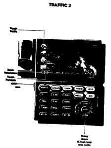
FIG. 32 illustrates a Weather Map Request page. The Weather Map Request page
is
accessed by pressing the Weather button 27n (shown in FIG. 2) on the PCD. The
Weather Map
Request page allows the PCD user to specify the map location and scale, the
map type, whether
the selected map should be automatically updated at specified intervals, and
whether a set of
maps should be displayed in a sequential fashion. The PCD displays a number of
different types
of weather maps, including satellite images, radar maps, temperature maps,
wind chill maps, and
any other type of weather map available. Some weather information is more
perfectly provided
by showing a sequence of displays indicating the change in weather over time.
Therefore, the
PCD allows the operator to sequentially display a set of maps, thus providing
an animated map
display.
-18-
CA 02347760 2001-04-19
WO 00/24131 PCT/US99/24868
1 FIG. 33 illustrates a weather reporting device. The weather reporting device
has a power
port 334 to provide electrical power to the weather reporting device. As with
the PCD, the
weather reporting device may also be powered by a battery (not shown). The
weather reporting
device also has a computer port 335, an interface port 333, an antenna port
332, a pressure access
port 331a, and a number of auxiliary ports 331b-e. The computer port provides
a
communications interface to a standard personal computer or the PCD. The
interface port
provides an interface to systems with weather detection features, such as
aircraft with weather
radars or lightning strike finders. The antenna port allows an external
antenna to be connected
to the weather reporting device, thereby providing remote operation
capability. The pressure
access port provides external access for an internal pressure sensitive device
(not shown) for the
determination of barometric pressure. A plurality of auxiliary input ports 441
b-a provide an
interface for connecting the weather reporting device to external weather
detection sensors such
as temperature sensors, wind sensors, and other weather sensing devices.
In one embodiment the weather reporting device additionally includes a coaxial
cable
port, a fiber optics port, and a telephone line port. The coaxial cable port
allows the weather
reporting device to be attached to a cable television distribution system.
Attachment to the cable
distribution system allows the device to transmit information over the cable
distribution system
to a central office of a cable television network. The fiber optic port
similarly allows the weather
reporting device to be attached to a fiber optic communications network. The
fiber optics
communication network may be either a cable television distribution system or
a telephone
distribution system. The telephone access port allows for the connection of
the weather reporting
device to a standard telephone network.
A condition reporting device is a weather reporting device, but with increased
capabilities. The condition reporting device further includes a radio radar
unit similar to those
used by police agencies to detect automotive vehicular speed. Alternatively,
the condition
reporting device may be equipped with sonar, infrared, or other distance
measuring devices.
FIG. 34 illustrates a block diagram of the condition reporting device (CRD).
The CRD
includes a processor 1200, memory 1202, a battery 1204, a speed detector 1206,
a digital camera
1208, a radio transceiver 12 i 0, an antenna 1212, a coaxial cable port 1214,
and sensors 1216.
The memory stores data pertaining to operation of the CR.D, including
instructions for execution
by the processor which controls operation of the CRD. Specifically, the
processor reads data
from the various sensors and transmits data via the transceiver. In one
embodiment the memory
additionally stores data pertaining to normal expected conditions, such as
normal temperatures
or traffic flow, at the CRD location. This data could take the form of merely
the average normal
temperature at the site, but more preferably provides daily or hourly normal
temperatures and
hourly traffic pattern information.
-19-
CA 02347760 2001-04-19
WO 00/24131 PCT/US99/24868
1 With respect to the use of the radar or other similar unit, the condition
reporting device
may be mounted on the sides of freeway overpasses or poles adjacent a
vehicular arterial route
to determine automotive vehicular speeds on the freeway or arterial route.
Alternatively, the
radar unit may be replaced by a sonar unit wherein the use of sound waves are
used in place of
radar waves to determine vehicular speed on the freeway or arterial route.
The condition reporting device additionally includes sufficient computer
memory to store
at least a single digitized video picture. The single picture is provided to
the condition reporting
device through the digital camera, which may be a charged coupled device (CCD)
coupled to the
condition reporting device through one of the auxiliary input ports. The
condition reporting
device may also obtain data representing the single digitized video picture
via a direct
transmission to the condition reporting device through the antenna of the
condition reporting
device. Thus, photographs in digital format obtained by others, such as
television news
helicopters, may transmit a digital picture to the condition reporting device
for storage.
The radio transceiver unit allows the condition reporting device to transmit
information
via radio signals both to end-users and to other condition reporting devices.
As illustrated in
FIG. 35, first through fourth condition reporting devices 1220a-d are located
alongside an arterial
route 1222. Traveling along the arterial route are automobiles 1224a,b. A home
1226 equipped
with a radio receiver 1228 is located near the arterial route. Specifically,
the home is located
most near the fourth condition 1220d reporting device, and most distant from
the first condition
reporting device 1220a. The automobiles receive information from the condition
reporting
devices via radio signals, as does the home, and thus end-users in the
automobiles and the home
receive up-to-date information regarding conditions along the arterial.
The end-users, however, may not desire information regarding road conditions
from
condition reporting devices which are close enough for the end-users to
receive radio
transmissions. Accordingly, the condition reporting devices are two-way daisy-
chained together.
That is, the second condition reporting device receives information broadcast
from the first
condition reporting device and the third condition reporting device. The
second condition
reporting device also transmits the information received from the first
condition reporting device
and the third condition reporting device in addition to the information
specific to the second
condition reporting device.
In one embodiment, the transmission of information is accomplished using a
time-interleaf method in which the second condition reporting device transmits
the information
received from the first condition reporting device over a first time interval,
and transmits the
information specific to the second condition reporting device over a second
time interval. In this
3 S time-interleaf method each condition reporting device in the daisy-chain
is programmed with the
number of other condition reporting devices in the daisy-chain, the
transmission frequency the
two closest condition reporting devices in the two-way daisy-chain, the total
number of condition
reporting devices in the chain, and the position of the condition reporting
device in the chain.
-20-
CA 02347760 2001-04-19
WO 00/24131 PC'T/US99/24868
1 The condition reporting device uses this information to determine the time
necessary to
receive transmissions from the two closest condition reporting devices in the
chain and to
determine the total transmission time for each cycle of transmission of the
condition reporting
device. For example, if each condition reporting device is allocated 30 second
for transmitting
S their own information, the total cycle transmission time is two minutes if
the first through fourth
condition reporting devices are two-way daisy chained together.
FIG. 36 illustrates a block diagram of a cable television distribution system
for the
weather reporting and condition reporting devices. A central cable television
office 1230
provides for transmission of television signals over land line 1231 to various
locations 1231 a-v.
The various locations may be residences, businesses, or other users of cable
television
distribution services. The land lines may be coaxial cable or fiber optic land
lines. A central
cable television office also provides Iinks 1236 to telephone and computer
networks for the
transmission of Internet-related data. Thus, the land lines provides two-way
communication
between the central cable television office and the various locations.
Also attached to the land line are condition reporting devices 1234. The
condition
reporting devices are attached to the land line either through the cable
access port or the fiber
optic access port, depending on the nature of the land line to the condition
reporting devices. The
condition reporting devices transmit digital data corresponding to the data
received by the devices
input sensors over the land line to the central cable television office. The
central cable television
office then transmits digital information received by the condition reporting
devices to the
residences in other locations, with each condition reporting device provided a
separate cable
television channel.
Thus, in one embodiment condition reporting devices may be located in a
variety of
geographic locations throughout a cable television distribution area.
Receivers ofcable television
may set their channels to a channel for a specific condition reporting device
and obtain weather,
traffic, and video information for a specific location within the cable
television broadcast area.
Moreover, condition reporting devices located in bass, restaurants, and other
venues may transmit
video pictures of the interior of such establishments as a form of advertising
for the
establishments, as well as for the entertainment of television viewers at home
or elsewhere.
The locations of the condition reporting devices are also tracked by a central
computer
system. The central computer maintains a database of the locations of
condition reporting
devices. For condition reporting devices located along roadways such as
streets and highways,
the central computer system also stores in the database an indication of the
road or highway along
which the condition reporting device is located. Further, many organizations,
particularly state
highway departments, maintain digital cameras providing roadway information
available over
the World Wide Web (WWW or WEB). The central computer system also tracks
locations of
these digital cameras, as well as other non-condition reporting devices.
-21-
CA 02347760 2001-04-19
WO 00/24131 PCT/US99/2486$
1 CRD location data may be used in conjunction with route information (plot
trail) stored
by the PCD. FIG. 37 illustrates a process for using the route information
stored by the PCD to
obtain information concerning the availability of condition reporting devices
from the central
computer system along the route stored by the PCD. In step 1240 a request for
condition
reporting device locations is transmitted by the PCD to the central computer
system. Any ofthe
communication means included with the PCD may be used to form such
transmission, with one
embodiment using cellular telephone communication. Included with the request
for condition
reporting device locations is data indicating the route information maintained
by the PCD. The
route information includes waypoint information for waypoints along the route.
Road and
highway identifiers are also transmitted when the route information also
includes road or highway
identifiers.
In step 1242 the central computer receives the condition report device request
from the
PCD. In step 1244 the central computer system determines the locations of
condition reporting
devices along the route. If the route information includes road or highway
identifiers, then the
central computer system identifies condition reporting devices along such
roads or highways, and
also determines the condition reporting devices along such roads or highways
within the latitude
and longitude constraints, as indicated by waypoints, of the route. This
process is performed for
each road or highway identified in the route information as being along the
route. If the route
information does not include road or highway identifiers, then the central
computer system
determines the locations of condition reporting devices within one-tenth of a
mile of the route.
The central computer system of course need not be limited to reporting
condition reporting device
locations within one-tenth of a mile of the route. Other distance values may
be used, and the
PCD may also transmit a requested search criteria to the central computer
system for use by the
central computer system.
In step 1246 the central computer system transmits condition reporting device
locations
along the route to a PCD. For each such condition reporting device, the
central computer system
also transmits information identifying methods of communication with the
condition reporting
devices. For example, some condition reporting devices may make data available
over computer
networks such as the Internet or World Wide Web. Other condition reporting
devices may only
transmit information via radio communications within a small area, or may be
part of a linked
condition reporting device system allowing for radio communication over larger
areas.
In step 1248 the PCD receives the locations of reporting devices. In step 1250
the PCD
correlates the condition reporting device locations to the route information
and forms a map
display indicating the trail plot and the condition reporting device locations
the process then
3 S returns.
FIG. 38 illustrates a display of a PCD displaying a trail plot with condition
reporting
device locations. As illustrated, the trail plot is indicated by a thick line.
The thick line follows
a first route 1262 until the first route intersects a second route 1260. The
plot trail thereafter
-22-
CA 02347760 2001-04-19
WO 00/24131 PCT/US99/24868
1 follows the second route. The locations of condition reporting devices 1264a-
b are indicated
along the route by star symbols (~).
Three methods are used by the PCD to obtain condition reporting device
information, a
manual method, an automatic hand-off method, and an automatic sequence method.
FIG. 39 illustrates a process of the manual method. In the manual method the
user of the
PCD slews the cursor over the reported location of the condition reporting
device in step 1270.
In step 1272 the user selects the condition reporting device identified by the
cursor. In step 1274
the PCD determines whether the condition reporting device is communicated with
a via a
computer network or via radio transmissions. If the condition reporting device
is communicated
with via a computer network, then the PCD transmits a request to the condition
reporting device
for data over the computer network in step 1275. If the condition reporting
device transmits
information via radio communications, then the PCD sets its radio receiver to
the appropriate
frequency for receiving transmissions from the condition reporting device in
step 1276. In step
1278 the PCD receives the information from the condition reporting device. The
PCD then
formats the data in step 1280 and displays the data in step 1282.
FIG. 40 illustrates a PCD display showing information received from the
condition
reporting device. The information from condition reporting device includes a
single digital photo
1284. The information received from the condition reporting device also
includes traffic speed
indications 1286 and current weather information, including temperature 1288
and wind speed
1289.
FIG. 41 illustrates a process of the automatic hand-off method for obtaining
condition
reporting device information. The automatic hand-off method is similar to the
manual method,
but the user of the PCD is not required to select condition reporting device
locations with the
cursor. Instead, the PCD maintains a sequential list of condition reporting
device locations along
the route. The sequential list is ordered by condition reporting device
locations along the route
such that a first condition reporting device expected to be encountered along
the route is placed
first in the list, and the last condition reporting device expected to be
encountered along the route
is placed last in the list. As the PCD travels along the route condition
reporting devices are
removed from the list when the PCD comes within a predetermined distance, one-
tenth of a mile
in the preferred embodiment, of the condition reporting device location.
When the user selects COND RPT on the PCD display the PCD determines which
condition reporting device is currently first on the list. The PCD then
contacts the condition
reporting device, as in the manual method, and displays the condition
reporting device
information, also as in the manual method. Once the PCD comes within the
predetermined
distance of the condition reporting device the PCD removes the condition
reporting device from
the list, and automatically requests information from the next condition
reporting device along
the route and displays such information.
-23-
CA 02347760 2001-04-19
WO 00/24131 PCT/US99/24868
1 Thus, as illustrated in FIG. 41, the process determines an ordered list of
CRDs along the
route in step 1290. In step 1292, the process causes information from the next
CRD to be
displayed. In step 1294 the process determines if the CRD whose information is
being displayed
is within a predefined distance of the PCD. Once the CRD is within the
predefined distance the
process deletes the CRD from the ordered list in step 1296. In step 1298, the
process determines
if the list is empty. If the list is empty, the process returns. Otherwise,
the process displays
information from the next CRD in the list to be displayed in step 1292.
FIG. 42 illustrates a process of the automatic sequence method for obtaining
condition
reporting device information. As in the automatic hand-off method, the PCD
maintains a
sequential list of condition reporting device locations along the route. The
sequential list is
ordered by condition reporting device locations along the route such that a
first condition
reporting device expected to be encountered along the route is placed first in
the list, and the last
condition reporting device expected to be encountered along the route is
placed last in the list.
Information from each condition reporting device in the sequential list is
displayed for a period
of time, in one embodiment ten seconds, and then the next condition reporting
device in the
sequential list is displayed. After information from the last condition
reporting device in the
sequential list is displayed, the PCD displays information from the condition
reporting device
first in the sequential list. As in the automatic hand-off method, as the PCD
travels along the
route, condition reporting devices are removed from the list when the PCD
comes within a
predetermined distance of the condition reporting device location.
Thus, as illustrated in FIG. 42, in step 1310, the process creates a travel
list comprising
a sequential list of CRDs expected to be encountered over the route. The
process causes data
from the first CRD in the list to be displayed in step 1312. The process then
determines if a
predefined time period has elapsed in step 1314. Once the predefined time
period elapses the
process determines if the list is empty in step 1316. If the list is empty the
process returns. If the
list is not empty the process causes display of data from the next CRD in the
list in step 1317.
The process then waits predefined time period in step 1318. When the
predefined time period
elapses the process determines if the end of the sequential list has been
reached in step 1320. If
the end of the list has been reached the process causes display of information
from the first CRD
in the list in step 1317. Otherwise, the process causes display of information
from the next CRD
in the sequential list in step 1317.
Thus, in either the automatic hand-off mode or the automatic sequence mode,
the user
may have a PCD in his automobile and be automatically informed of current road
conditions
along the expected route. If road conditions are reported as unpassable due to
weather or traffic,
then the user may appropriately plan to take alternate routes.
The use of the PCD in conjunction with CRDs accordingly provides the PCD user
the
capability to receive up-to-date detailed information regarding conditions
along the PCD user's
-24-
CA 02347760 2001-04-19
WO 00/24131 PCTNS99/24868
1 route. This allows the PCD user to plan use alternative routes as conditions
warrant. Such
planning is further enhanced by an alternative route (ALT RTE) function of the
PCD.
The ALT RTE function of the PCD uses current speed information from CRDs along
the
user's route, and alternatives to the user's route, to determine travel times.
FIG. 43 illustrates a
PCD display showing a user's route 1300 comprised of multiple segments 1300 a-
d. The user's
route follows a first street 1300a, a first highway 1300 b, and a second
highway 1300c. Roads
and highways near the users route include a second street, a third street
1304, and a fourth street
1306. The user's route includes a segment A which follows the first street
1300a in a southerly
direction to the first highway 1300b, which runs in a east-west direction. The
user's route then
has a segment B which follows the first highway 1300b in a westerly direction
until the first
highway intersects the second highway 1300c, which runs in a north-south
direction. The user's
route then has a segment C which follows the second highway 1300c until the
termination of the
route at the intersection of the second highway 1300c and the fourth street
1306.
Alternatively, the user could take a route including a second street 1302
which runs in a
east-west direction, a third street 1304 which runs in a north-south direction
and intersects the
second street and the fourth street 1306. The second street is comprised of a
segment D from the
user's start point to the third street, and a segment E from the third street
to the second highway.
The third street is similarly comprised of a segment F and a segment G.
Condition reporting devices 1308a j are located at various points along the
streets and
highways. The condition reporting devices provide traffic speed and weather
indications through
the PCD via methods discussed above. The map information made available to the
PCD and
stored by the PCD contains distance information. The PCD therefore is able to
make use of the
traffic speed information and the distance information to determine travel
times for the various
route and route alternative segments. Real time calculation and display of
segment travel times
accordingly allows the PCD user to accurately determine and estimate travel
times to particular
destinations over a plurality of different roads and road segments.
FIG. 47 illustrates a process of determining travel times. In step 1390, the
process reads
route information stored by the PCD. In step 1392, the process determines if
the user has
provided alternative route segments. If the user has provided alternative
route segments the
process reads information describing the alternative route segments in step
1394. Otherwise, the
process determines alternative route segments in step 1396. Regardless, if the
source of the
alternative route segments, the process determines travel times for each of
the route segments;
and the route as a whole, in step 1398. The process then returns.
FIGS. 48A-H and FIGS. 49A-G illustrate an alternate embodiment of a PCD. The
alternate embodiment includes an alphanumeric keypad with special function
keys, a display
screen, a microphone and speaker, an antenna, and a digital camera. The
alphanumeric keypad
includes a power button, alphanumeric keys corresponding to those keys
generally found on cell
phones, and special function keys. The special function keys include a
Navigate key, a C-Mail
-25-
CA 02347760 2001-04-19
WO 00/24131 PCTNS99/24868
I key, and a Phone key. The special purpose keys further include a Store key,
a Zoom key, and a
Clear key, as well as an Enter key and a Home key and a Send, Recall, and an
End key. As with
the previously described version of the PCD, the PCD is equipped with a GPS
receiver system
so as to be able to use the global positioning satellite system to accurately
determine the location
of the alternate PCD.
The camera is a digital camera, which includes a sensing housing containing a
charge
coupled device (CCD) or other digital imaging device. The image formed by the
digital camera
is stored on memory contained within the PCD device, along with a GPS stamp.
The GPS stamp
is placed within the picture image in a manner similar to the placing of a
time or date stamp on
a digital image picture. Of course, methods and apparatus such as those
described in U.S. Patent
No. 4,402,588, the disclosure of which is incorporated herein by reference,
may be used.
However, in the embodiment described the GPS stamp is placed into the image by
overriding
areas of memory with the GPS provided data. The GPS stamp provides latitude
and longitude
information, and serves as a convenient way of accurately placing the location
of images.
1 S In addition, the use of a camera with the PCD device allows the PCD device
to serve as
a mobile condition reporting device (CRD). The image taken using the PCD
camera, along with
the appropriate GPS stamp, is provided by the cellular communication
capability, included with
the device, to a central computer storage system. The central computer storage
system then
makes the CRD device data available, in the manner as previously described, to
those requesting
condition reporting device data.
In one embodiment, operators of the PCD device with camera can also indicate
road
status information. Road status information may be important, fox example, in
the event that a
road is closed. In such an occurrence, viewers of CRD data might believe that
a road is free and
clear of traffic, when in fact the road is impassable. Furthermore, images of
the roadway may
not accurately describe all of the road conditions, such as ice or high winds,
which may also
impact roadway usage. Accordingly, the user has the option of tagging each
image with a
roadway status, with the possible status being open, closed, or caution. In
one embodiment the
central computer facility, however, will only include roadway status
information if the person
providing the roadway status information supplies a specified security code.
This allows for only
authorized personnel to update road status information. This prevents users
from changing
roadway status information so as to affect traffic patterns in such a manner
that they may more
freely use roads.
In one embodiment, all images taken using PCDs are automatically provided to
the central
computer facility. In another embodiment, users provide security level
information for each
image, which may be provided via default security level, with only images of a
certain predefined
security level transmitted to the central facility.
FIG. 44 illustrates a block diagram of a local area transmission system for
providing
multimedia information using GPS navigation system coordinates. Data i 330
pertaining to a
-26-
CA 02347760 2001-04-19
WO 00/24131 PCTNS99/24868
1 local geographic area is maintained by cellular telephone system providers
or other entities. The
particular local geographic locations are based on the locations of cell sites
for cellular telephone
networks, and the location specific data is transmitted by a cell site 1332
both over a standard
radio broadcast system using a radio transmitter 1334 and by request to the
cell site via a
telephone access number. This data includes ASCII or other text formats,
digital graphical
images, including maps, digital photo-based images, and audio data.
In the radio broadcast system method of transmitting data, a first radio
frequency is used
to inform receivers of the radio broadcast of specific frequencies to be used
to obtain particular
types of data. The specific frequencies continually transmit data pertaining
to services and
information of the type specified for the particular frequency. The data
includes text and graphics
normally including names, addresses, phone numbers and GPS locational
information for
providers of the services of the type for that frequency. Additionally,
digital GPS maps for the
particular cell site broadcast location are also included.
Similarly, each cell site location is provided a specific telephone number.
Users of
cellular telephone-capable devices call the number and are in turn provided a
list of telephone
numbers for providing data equivalent to the data provided by the radio
broadcast system. Two
sets of phone numbers are provided. The first set provides voice audio
information, and the
second set provides information in digital form. In one embodiment, users of a
PCD then direct
the PCD device to obtain digital text, graphical maps, and GPS location
information from the cell
site telephone number. This information may then be used by the user of the
PCD device to
determine route information and to obtain data in the same manner as from
other GPS tagged
data providers.
FIG. 45 illustrates a method of directing a PCD to obtain restaurant-related
information
from the cell site telephone number. In step 1340 the PCD displays a screen
having PHN #,
PHN/EMAIL, and RTN ADDRS entry fields. The user enters the cell site telephone
number in
the PHN # entry field, P or E in the PHN/EMAIL entry field, and either the
phone number of the
PCD or an e-mail address in the RTN ADDRS entry field. In step 1342 the user
enters
information in the PHN #, PHN/EMAIL, and RTN ADDRS entry fields. If the user
enters P in
the PHN/EMAIL entry field, then the user should also enter the phone number of
the PCD in the
RTN ADDRS entry field. If the user enters E in the PHN/EMAIL entry field, then
the user
should enter an e-mail address in the RTN ADDRS entry field.
In step 1344 the user selects the TRNSMT option and the information entered by
the user
in step 1342 is transmitted by the PCD to the cell site telephone number. In
step 1346 the cell
site computer system determines which information pertains to the cell site
telephone number.
3 5 In step 1348 the cell site computer system determines whether the
information transmitted by the
PCD included a P or an E in the PHN/EMAIL field. In step 1352 the cell site
computer system
instructs the cell site to transmit the information pertaining to the cell
site telephone number to
the phone number transmitted by the PCD in the RTN ADDRS field if the
PHN/EMAIL field
-27-
CA 02347760 2001-04-19
WO 00/24131 PGT/US99/24868
1 contains a P. In step 1350 the cell site computer system transmits an e-mail
message to the
e-mail address transmitted by the PCD in the RTN ADDRS field if the PHN/EMAIL
field
contains an E.
Each cell site data provider additionally provides traffic and weather
information for the
cell site. By way of example, a central data provider may receive weather and
traffic information
from weather reporting devices and condition reporting devices and store that
data by the latitude
and longitude location of those devices. This data may be then transmitted
over a particular
frequency or made accessible by having users call a particular telephone
number so that
individuals may obtain accurate and timely weather and traffic information
regarding specific
localities.
The PCD also serves as a position monitoring device. To begin the position
monitoring
function the user selects the monitor on the PCD. Upon selecting the monitor
function, the PCD
displays a menu including INTERROG, AUTO-TIMED, and MOVE options. When the
INTERROG function is selected the PCD will display an e-mail entry field
allowing input by the
user of an e-mail address. After the e-mail address is entered, the PCD
responds to appropriate
interrogatories by transmitting its current position. An appropriate
interrogatory includes the
security code active when the INTERROG mode was selected and an Internet e-
mail address.
Upon receipt of an appropriate interrogatory the PCD will transmit the GPS
receiver determined
latitude and longitude of the device to the e-mail address.
If the user selects the AUTO-TIMED option the PCD displays a time entry field
and an
e-mail address entry field. After entry of the time entry field and the e-mail
address, the PCD
will count down the time period entered by the user, and, upon the completion
of the time period,
transmit an e-mail to the entered e-mail address indicating the PCD location.
After transmitting
the PCD location to the e-mail address, the PCD will begin counting down the
time period
previously entered by the user, and once again transmit the PCD location upon
the completion
of the time period. Thus, for example, if the user enters the time 30 minutes
into the time field
and the e-mail address of abc@def.com, then every 30 minutes the PCD will
transmit the PCD
location to abc@defcom.
When a user selects the MOVE option the PCD displays a distance entry field
and an
e-mail address entry field. After entry of the distance field and the e-mail
address field, the PCD
transmits an e-mail containing the device location to the e-mail address
specified in the e-mail
field whenever the PCD moves a distance greater than the distance entered in
the distance field.
When the PCD transmits an e-mail indicating the device position, the current
device position is
stored and the PCD waits until the device has moved the distance specified in
the distance field
from the current location prior to again transmitting the PCD location to the
e-mail address
specified in the e-mail address field.
Thus, the PCD can be used to monitor the locations of individuals utilizing
PCDs. For
example, credit authorization agencies may make use of the location monitoring
capability
-28-
CA 02347760 2001-04-19
WO 00/24131 PCT/US99/24868
1 provided by the PCD in determining the validity ~uf credit requests. FIG. 46
illustrates a method
of credit authorization using the PCD. In step 1360 an individual makes a
request for credit.
This may be accGmplished in a variety of manners, including "swiping" a credit
card through a
credit card reader at a gas station, supermarket, or a variety of other
locations, or merely by
providing a credit card to a retail clerk who thereafter requests credit
authorization. The request
for credit may be made to a credit card issuer, or may merely be a request for
credit authorization
by a credit reporting facility.
In step 1362 the request for credit is transmitted to a credit authorizer. In
step 1364 the
credit authorizer determines whether credit authorization is appropriate in
view of the credit
authorizer's prior art credit authorization practices. Such prior art
practices include the use of
credit limits, past credit usage, and other factors. If the credit authorizer
determines that credit
authorization according to prior art practices is not appropriate, then credit
authorization is denied
in step 1366. If credit authorization according to prior art practices is
appropriate, then the credit
authorizer transmits an interrogatory to the individual's PCD in step 1368. In
step 1370 the credit
authorizer waits a predetermined time for a response from the PCD. In step
1371 the credit
authorizer determines if a response from the PCD has been received. If a
response from the PCD
has been received, the credit authorizer determines if the PCD location is
consistent with the
request for credit in step 1372. This may be accomplished by determining if
the PCD is at the
location from which credit was requested. If the reported location is
consistent with the request
for credit, then the process grants or authorizes credit in step 1378. If the
reported location is not
consistent with the request for credit, the process denies credit in step
1366. If no response is
received from the PCD, the credit authorizer determines if previous PCD
reported locations are
consistent with the location from which credit was requested in step 1374. For
example, the
credit authorizer may have received responses from previous requests for
position from the PCD,
or an e-mail address of the credit authorizer may have been entered by the
individual for
AUTO-TIMED or MOVE position updates. If the previous location is consistent
with the request
for credit, then the process grants or authorizes credit in step 1378. If the
previous locations is
not consistent with the request for credit, the process denies credit in step
1366.
Additionally, PCDs can be used to monitor automobile locations and thereby
discourage
automobile theft or aid in the recovery of the automobile. For example, for an
active PCD left
in the INTERROG mode, upon discovery of the theft of the PCD or item in which
the PCD is
located, the user merely need to interrogate the PCD as to its location and
thereafter be
immediately informed as to the device location, thus allowing for ease in
locating and returning
the device to the proper user.
As another example, the user can leave the active PCD in MOVE mode, with the
user's
e-mail address designated as a recipient of the location of the PCD device.
Thus, whenever the
PCD, or object in which the PCD is located, is moved the user can receive
instantaneous
notification of the movement of the PCD and any object carrying the PCD.
Further, in one
-29-
CA 02347760 2001-04-19
WO 00/Z4131 PCT/US99/24$68
1 embodiment of the invention, the user may select a SECURITY option from the
main menu. In
the SECURITY option the PCD is automatically configured in the MOVE mode, and
the PCD
is also automatically configured to transmit an e-mail to a user defined
address in addition to any
other addresses specified in the MOVE mode. The user defined address is
preferably that of a
police agency or security service. Further, in one embodiment of the
invention, the PCD
additionally places a telephone call via the PCD's cellular telephonic
capabilities to a user
defined telephone umber. Upon answer by the receiving telephone the PCD
automatically
transmits an indication, which may be a prerecorded voice message, that the
PCD has moved
from its prior location. In addition, the user defined telephone number may be
the universal
telephone number of the user, which is later herein described. In the event
the predefined
telephone number is the universal telephone number of the user the PCD
additionally transmits
a password corresponding to security level. The password and security level
are selected by the
user, and are also later herein described in conjunction with the universal
telephone number.
In accordance with the present invention, the central computer system also
maintains
information in a database allowing individual users to be easily located both
physically and in
terms of their electronic communication locations. The central computer system
maintains a
database of individuals and an Internet address linked to each individual. The
Internet address
linked to each individual need not be a unique address, but instead many
individuals may make
use of a single computer indicated by the Internet address in the Internet
address field. For
example, for many cases the central computer system may be the computer system
identified by
the Internet address.
The system also contains a large number of computer systems linked by the
Internet, and
which are the computer systems pointed to by the address field for the
individuals in the Internet
address field. Each of these computers form a home site computer system. The
responsibility
of maintaining the home site computer systems are the responsibility of the
individuals.
The home site computer system maintains electrvriic contact information and
geographic
location of the individual. The electronic contact information includes home
telephone numbers,
office telephone numbers, cellular telephone numbers, fax numbers, and e-mail
addresses. The
geographic location is provided in terms of latitude and longitude, although
street addresses or
site names can also be provided with the latitude and longitude.
Also linked to each electronic communication identifier in geographic location
information is a security level index. In one embodiment, the security level
index is a number
between one and ten. The individual assigns security level indexes for each
item of information.
The user also identifies other individuals who may wish to contact the user,
and indicates which
security index level each such other individual should be provided. Other
individuals who are
not identified by the user are provided a default security level index. When
the home site is
contacted by another individual, the other individual provides an identifier,
such as the
individual's name to the home site. In one embodiment the other individual
also provides a
-30-
CA 02347760 2001-04-19
WO 00/24131 PCT/US99124868
I password to the home site so that the home site may authenticate the
identity of the individual.
Based on the identity of the individual, preferably authenticated, the home
site determines the
other individual's security level index.
The other individual is thereafter only able to obtain information for the
other individual's
security level index value and those values below the other individual's
security level index. For
example, a user's general office work number may be assigned a security level
index of ten, with
the user's direct line phone number provided a security level index of six. A
first other individual
with a security index level of seven can only obtain the user's general office
number while a
second other individual with a security index level of six can also obtain the
user's direct line
phone number.
The user's geographic location is updated through the PCD. As previously
discussed, the
PCD can be used to provide e-mails indicative of the user's location in
varying manners. When
the user's home site computer system is identified as an e-mail address for
such updates, the
user's home site computer system may track the user over time. In one
embodiment of the
invention, the user's home site computer system is always provided a copy of
any e-mail position
updates provided by the PCD.
The capability to track individuals is further enhanced through the use of
condition
reporting devices. For example, a particular user is identified as being at a
particular location,
other individuals may request via the central computer system the location of
condition reporting
devices in that area. If the condition reporting device has digital picture
capability, then the other
individuals may request information from the particular condition reporting
device and determine
if the user is in fact at the location. Thus, the system of the present
invention provides a method
and system for tracking individuals, and for confirming the presence of
individuals at particular
locations.
In another embodiment of the invention, the user's home site computer system
maintains
a universal phone number, fax number, and e-mail address for the individual.
When other
individuals try to contact the user via the general phone number, fax number,
or e-mail address
the home site computer system automatically routes the incoming call, fax, or
e-mail to the phone
number, fax number, or e-mail address currently indicated as active for the
individual. This
routing is done, however, in conjunction with the other individual's security
index level. Thus,
if the active phone number for the user is the user's cellular telephone
number, but the other
individual does not have a security level index sufficient to determine the
user's cellular
telephone number, then the call to the user by the other individual will be
automatically routed
to the phone number with the highest number security level index available to
the other
3 5 individual. If the telephone number to which the other individual has been
routed is not currently
active for the user, the other individual will be left in a voice mail or
other automatic answering
system if available. Thus, users may selectively forward phone calls,
facsimiles, or e-mails
depending on requirements of the user.
-31-
CA 02347760 2001-04-19
WO 00/24131 PCT/US99/24868
The home site computer system maintains data indicative of the location of
telephone
numbers, fax numbers, and e-mail addresses. As the user's geographic location
is updated
through use of the PCD, the home site computer system automatically maintains
a list of active
phone numbers, facsimile numbers, and e-mail addresses for the user. Thus, if
the user's
geographic location as provided by the PCD indicates that the user is at the
user's office, then the
user's office phone numbers are made active. If the user's geographic location
as provided by the
PCD indicates that the user is at the user's home, then the user's home phone
numbers are made
active. If the user is at an undetermined location, then the user's home site
computer system
identifies the user's cellular telephone as the active phone. Thus, phone
calls, facsimiles, and
e-mails may be automatically routed, using call forwarding technology known in
the art, to the
electronic communication access number of the user without resort to
sequentially calling various
phone numbers.
In addition, in order to contact an individual only the universal phone
number, facsimile
number, and e-mail address need be known. Thus, as actual phone numbers and e-
mail addresses
change due to changes in telephone area codes, zone prefixes, or changes in
the locations of
homes and businesses, individuals need only update the information maintained
by their home
system in order to be able to be contacted by those desiring to communicate
with them via
electronic means.
The user's home site computer system also serves as a repository for data for
use with the
user's PCD. One purpose in providing such a repository is that the PCD may be
unable to store
all data requested from a data provider or other parties due to device memory
constraints. For
example, the user may request a map of a relatively large area and a
relatively great amount of
detail. Such a map may be too large for storage in the memory of the PCD. The
user could
request a subset of the desired map, if such a request or map is available,
and request further
subsets of the map as desired. Such a method, however, entails repeated
reaue~t~ fnr man
information, and is also inconvenient if a single map section is repeatedly
later used after other
map sections are requested. Accordingly, the home site computer system
provides a repository
for such material. Data providers and information suppliers, instead of
downloading data directly
to a PCD in response to a request for information by a PCD, instead route data
to the user's home
site computer system.
In one embodiment, requests from a PCD for data include an indication of
allowable
memory space for downloaded data. The allowable memory space may be
automatically
determined by the PCD based on the total device memory and the memory
available at a given
time. Thus, if a particular PCD can only accommodate additional data of 8
megabytes or less,
the request for information would indicate a maximum download data size of 8
megabytes.
Alternatively, the allowable memory space may be set by the user.
After the data provider or other information supplier receives a request for
information,
the data provider or information supplier then transmits the requested data to
the home site
-32-
CA 02347760 2001-04-19
WO 00/24131 PCT/US99/24868
1 computer system, via e-mail or other means described herein, in multiple
files, each less than the
maximum memory size of the PCD. The data provider or information supplier
determines which
information, such as map information is responsive to the request, and
prepares individually
readable and displayable files, or data packets, less than the allowable
memory size. The user
may thereafter request the data directly from the home site computer system,
and later reuse the
same information at the user's convenience. In addition, the user is also able
to use the requested
data using other PCDs, or even other computer systems.
While this invention has been described with reference to illustrative
embodiments, this
description is not intended to be construed in any limiting sense. Various
other embodiments of
the invention will be apparent to persons skilled in the art upon reference to
this description. It
is therefore contemplated that the appended .claims will cover any such
modifications of the
embodiments as fall within the true scope and spirit of the invention.
20
30
-33-