Note: Descriptions are shown in the official language in which they were submitted.
CA 02349243 2001-05-31
1
H-205869
METHOD OF FORMING A COMPOSITE
ARTICLE WITH A TEXTURED SURFACE
TECHNICAL FIELD
The present invention generally relates to a method for
producing textured composite articles. More particularly, this invention
relates to a method by which a textured surface is produced on a composite
article through the use of a textured interfacial layer that is applied to the
mold
in which the article is subsequently formed, and c~rherein the textured
interfacial layer is retained on the article surface after the molding
operation
as a removable protective coating that when removed exposes the textured
surface of the article.
BACKGROUND OF THE INVENTION
Open tool molding is a process for producing relatively lowcost
composite panels at low volumes. While steel molds are often used for other
molding operations, the open tool molding process was developed to use less
1 s expensive one-sided epoxy or polyester molds to produce various products,
such as recreational vehicle (RV) composite panels with an in-mold finish. In
this process, the mold surface is cleaned and waxed, after which a layer of
gel
coat is applied and then partially cured. A laminate is then applied to the
gel
coat layer, and the laminate and gel coat are cured to form a unitary part
2o having a surface that is defined by the cured gel coat. Molded parts can be
produced by this method to have a class A finish lbearing any desired color
originally carried by the gel coat.
While the use of a low-cost epoxy ~or polyester mold offers
25 significant cost advantages over other molding methods used to produce
composite articles, there are certain limitations imposed by a polymeric mold.
One such example is the molding of panels, such as automotive interior
CA 02349243 2001-05-31
2
panels, for which a textured finish is desired. In the past, plastic textured
panels have been made by either injection molding or compression molding
using steel molds. A grained profile is formed on the surface of the steel
mold during the tool making process. The grained surface profile is then
transferred onto the surface of the molded parts, creating a textured surface
finish. Because of the hardness of the steel molds, the grained surfaces
maintain their appearance for many years of production. In contrast,
polymeric molds do not have the same level of hardness and, therefore, a
grained surface created on a polymeric mold wears out quickly. The vertical
walls of a grained polymeric mold are particularly vulnerable to wear during
demolding, with the result that an uneven surface finish is produced after
molding only a few parts. Consequently, polymeric open tool molds have
been generally limited to molding articles with smooth, glossy surfaces.
~5 In view of the above, it would be desirable if a method were
available for producing composite articles with a textured finish using a
lowcost polymeric mold whose mold surfaces are not damaged by the molding
operation.
2o SUMMARY OF THE INVENTION
The present invention is directed to a molding process that uses
an interfacial layer to isolate the surface of the mold from the surface of a
composite article produced with the mold. According to the invention, a
solution can be deposited on the mold surface to form the interfacial layer,
25 whose surface opposite the mold surface is texture°d. The texture of
the
interfacial layer is then transferred to the surface of the composite article
produced with the mold. After demolding, the interfacial layer is removed
from the article to expose an underlying textured surface of the article.
3o A suitable molding process of the present invention generally
entails spraying a polymeric solution on an untext:ured mold surface of a mold
CA 02349243 2001-05-31
3
so that the polymeric solution forms the textured interfacial layer of this
invention. According to the invention, certain spray techniques are capable of
depositing a polymeric solution to produce an interfacial layer whose outer
surface texture can be controlled by the spray par~nneters, such as pressure
s and spray gun orifice size. A composite material is then deposited on the
textured interfacial layer so that the composite material contacts the
textured
interfacial layer and has a surface that is textured by the interfacial layer.
The
composite material and the textured interfacial layer are then cured so that
the
composite material forms a composite article having a textured surface, and so
1o that the textured interfacial layer clings to the textured article surface.
The
textured interfacial layer can then be immediately removed from the composite
article, or left on the article as a temporary protecaive coating during
shipping
and handling and then later removed prior to or after the article is installed
or
assembled with other components.
is
In view of the above, a significant advantage of this invention is
that an open tool mold can be fabricated to have smooth mold surfaces, with
the interfacial layer being the sole means for producing a textured surface on
an article produced with the mold. As a result, molds formed from lower cost
2o and less durable materials, particularly polymers such as epoxies and
polyesters, can be used to produce articles with textured surfaces, without
quickly damaging or wearing out the mold surfaces.
Other objects and advantages of thus invention will be better
2s appreciated from the following detailed description.
BRIEF DESCRIPTION OF THE DRAWINGS
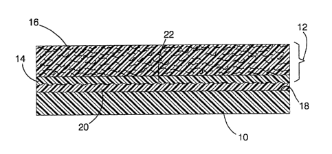
Figure 1 represents a cross sectional view of an open tool mold
for producing a composite article with a textured surface in accordance with
3o the present invention.
CA 02349243 2001-05-31
4
DESCRIPTION OF THE PREFERRED EMBODIMENT
The.present invention is the result of an investigation directed
to developing alternative methods for producing textured fiberglass composites
using the open tool molding process. As discussed previously, current
s technology has required the construction of a steel mold with a textured
mold
surface to produced textured composite articles. 'The present invention avoids
the high cost of texturing a steel mold through the: use of a removable
textured
interfacial layer, which allows less durable mold materials to be used as
lowcost replacements for a textured steel mold. According to the present
1o invention, when properly sprayed onto a smooth open tool mold, a polymeric
solution can be dried to form an interfacial layer having a surface texture
that
can be negatively cast onto a composite article produced with the mold,
thereby generating a textured surface on the article. When the article is
demolded, the interfacial layer releases from the mold and adheres to the
15 textured surface of the article. The interfacial layer can then serve as a
protective layer to reduce the risk of scratching or marring the textured
surface of the article during handling and storage. At any time after molding,
the interfacial layer can be readily removed from the composite article to
reveal the textured article surface. For example, the textured interfacial
layer
2o can be removed from the article after the article h.as been transported to
another facility for assembly or installation.
Illustrated in Figure 1 is a cross-section through a portion of an
open tool mold 10 on which a composite article 12 is in the process of being
2s cast. As is typical in the art, the article 12 is formed by depositing a
gel coat
layer 14, over which a fiber-reinforced laminate l'.6 is applied. Following
curing in the mold 10, the gel coat layer 14 and l~uninate 16 form the unitary
article 12 whose outer surface is defined by the cured gel coat layer 14.
Various compositions can be employed for the gel coat layer 14 and laminate
30 16. Because the gel coat layer 14 defines the outer surface of the article
12
after molding, the materials for the gel coat layer 14 and laminate 16 must be
CA 02349243 2001-05-31
compatible. In one embodiment that achieved particularly desirable
processing and wetting properties, the laminate 16 was formed by a mixture of
one-inch (about 25 mm) long glass fibers and a resin chemistry containing:
5 100 parts of an unsaturated polyester resin with a styrene
monomer content of about 32 % , available from Alpha/Owens-Corning under
the name H834. The resin is a malefic anhydride-lbased unsaturated polyester
modified with dicyclopentadiene, and contains a thixotrope and cobalt 2-
ethylhexanoate as a promoter that reacts with methyl ethyl ketone peroxides
(MEKP) to facilitate curing at room temperature. The resin has a specific
gravity of about 1.100 g/cc and a Brookfield viscosity of about 670 cps using
an RVF viscometer at 20 rpm with a #i'3 spindle.
0.81 parts of a wetting and dispersing additive having a specific
gravity of about 1.010 g/cc and available from BYK under the name W-972.
0.23 parts of a wetting and dispersing additive having a specific
gravity of about 0.930 g/cc and available from BYK under the name R-605.
0.23 parts of a silicon-free air release additive available from
BYK A-555 to reduce foaming.
23 parts of a calcium carbonate (CaC03) powder with a particle
size of about 5 micrometers.
1.23 parts of a fumed silica thixotrope available from Cab-O-Sil
under the name TR-720; specific gravity of about 0.050 g/cc.
1.50 parts of a methyl ethyl ketone peroxide (MEKP) available
3o from Elf Atochem NA under the name DDM-9; specific gravity of about
1.084 g/cc.
CA 02349243 2001-05-31
6
The gel coat layer 14 was a polyester-based material, and therefore chemically
compatible with the laminate 16. Suitable thicknesses for the gel coat layer
l4
and laminate 16 are about 0.5 mm and about 3 mrn, respectively, though it is
s foreseeable that various thicknesses could be used. Because the outer
surface
of the article 12 is defined by the cured gel coat layer 14, it is often
desirable
that the gel coat layer 14 contain pigmentation to produce a particular color
desired for the article 12.
1o Also shown in Figure 1 is an interfacial layer 20 between the
surface 18 of the mold 10 and the article 12. As depicted in Figure 1, the
surface 18 of the mold 10 is smooth while the surface 22 of the interfacial
layer 20 opposite the mold 10 is textured. Accordingly, the surface 22 of the
interfacial layer 20 defines the molding surface to the article 12, such that
the
1s surface 18 of the mold 10 is not subject to damage and wear during the
process of removing the article 12 from the mold 10. Therefore, a particular
feature of this invention is that the mold 10 can bf: formed from materials
that
are far less durable and wear-resistant than steel, including polymers such as
epoxies and polyesters. However, it is foreseeable that the advantages of this
2o invention could be realized with other types of mold tooling and other mold
materials.
According to the invention, the interfacial layer 20 can be
formed to have a desired surface texture by spraying an appropriate polymeric
25 material onto the mold surface 18. Suitable polymeric materials include
polyvinyl acetate solutions and acrylic latex emul;>ions, though other film-
forming materials could foreseeably be used. A variety of factors were
considered in the development of the present invention. For instance, in
addition to being appealing to the eye and touch, the texture produced on the
3o article 10 should be consistent throughout the pare: and repeatable from
part to
part. Also, in order to be easily removed, the interfacial layer 20 should not
CA 02349243 2001-05-31
7
chemically react with the gel coat layer 14 or the mold 10. Furthermore, the
interfacial layer 20 should have an acceptable curt: time and minimal
thickness
to be cost effective. As will be evident from the following discussion,
investigations leading to the present invention evidenced that the spraying
technique and thickness of the interfacial layer 20 can and must be
appropriately controlled to produce the desired degree of texturing for the
coating surface 22 and to promote the ease with which the interfacial layer 20
is subsequently removed from the article 12 after the molding operation.
The steps generally entailed in producing the composite article
12 in accordance with Figure 1 are to first clean a.nd then deposit a suitable
mold release agent on the surface 18 of the mold 10. The interfacial layer 20
is then deposited to a suitable thickness and dried before spraying a gel coat
material on the interfacial layer 20 to form the gel coat layer 14. A second
layer of mold release agent may be directly applied to the surface of the
interfacial layer 20 prior to forming the gel coat layer 14 in order to
facilitate
later removal of the interfacial layer 20 from the article 12. The gel coat
layer
14 is then partially cured, after which the laminate 16 is applied. The
interfacial layer 20, gel coat layer 14 and laminate 16 are then fully cured
before demolding, yielding the article 12 having a~ textured surface defined
in
the gel coat layer 14 and covered by the interfacial layer 20, which can be
removed at any desired time.
In a series of investigations leading; to the present invention, an
acrylic latex emulsion commercially available from AC Products under the
name AC940-Blue was used in the form of an aqueous solution. The emulsion
was used as received or diluted by about 10% demonized water. Various spray
techniques and equipment were evaluated in the investigation, including
gravity pot, siphon pot and pressure pot spray guns, and electric and airless
3o pumps equipped with various nozzles. In one investigation, it was shown
that
if the interfacial layer thickness is not sufficient, the process of removing
the
CA 02349243 2001-05-31
8
interfacial layer 20 is often difficult and time consuming. On the other hand,
an excessive interfacial layer thickness unnecessarily increases manufacturing
costs. Therefore, studies were conducted with lx:l ft. (about 0.3x0.3 m) flat
glass molds prepared with a mold release agent commercially available from
s Meguair under the name Mirror Glaze #8 Maximum Mold Release Wax.
Interfacial layers 20 were formed by spraying a coating solution on the molds
using a Binks (MODEL M1-G) gravity-feed high-volume low-pressure
(HVLP) spray gun using a spray tip number 10 and an air pressure of about
15 psi (about 1 bar). The coating solution was prepared by diluting the
acrylic
to latex emulsion noted above with deionized water in a 10:1 emulsion:water
ratio. The molds were placed in a paint spray booth at nominal room
temperature and humidity levels, with airflow through the booth set to produce
a slight negative pressure. The coating solution was sprayed onto the molds to
produce various wet film thicknesses as measuredl by a Binks wet film
15 thickness gauge. After air drying for twenty-four hours to form a solid
textured interfacial layer, a gel coat material and fiberglass composite
laminate
were applied to each coated mold and cured, after which the resulting cured
panels were removed from the molds. The adhesion of the interfacial layers
to the panels was then observed at nominal room temperature and humidity,
2o after which the dry film thicknesses of the interfacial layers were
measured
using a film thickness gauge.
Table 1 summarizes the results of this investigation.
25 Table 1.
Film Thickness Observations
0.04 ~ 0.01 mm Tore easily; very difficult to remove
0.12 ~ 0.02 Removed with little tearing
0.16 ~ 0.02 Removed easily with no tearing
30 0.21 ~ 0.02 Premature removal during panel demolding
0.25 ~ 0.02 Premature removal during panel demolding
CA 02349243 2001-05-31
9
The results indicated that a minimum dry film thickness of
about 0.1 mm was necessary to facilitate the removal of the interfacial layers
from the panels, while dry film thicknesses of greater than 0.18 mm resulted
in the interfacial layers preferentially adhering to the molds instead of the
panels. From these results, it is believed that spraying a mold release on the
textured surface of the interfacial layer could furt)Zer reduce the minimum
film
thickness, though also increasing processing costs. A suitable mold release
for this purpose would be Frekote-700, commercially available from Frekote,
1o though it is foreseeable that other mold release compositions could be
used.
The drying time of the interfacial layers was shown to be a
function of film thickness air circulation and temperature. An undiluted
coating solution deposited to a thickness of about 0.1 mm was found to have a
drying time of less than thirty minutes at a temperature of about 42°C
using
an air circulation of about 0.6 m/s.
In a second investigation, the ability to produce a dry interfacial
layer on the mold with consistent texture was evaluated. Several tests were
2o conducted to determine the optimum method of spraying the solution for the
interfacial layer. As before, nominal room temperature and humidity levels
and a slight negative pressure were established in a spray booth. Molds in the
form of flat glass plates (30x30 cm) were placed i.n a horizontal position in
the
booth. Prior to spraying, the surfaces of the plates were prepared with a mold
release agent. Spray pressures, nozzles and spray distances were varied
throughout the tests in attempts to achieve a uniform texture. Since the
texture of an interfacial layer is the negative image of the texture of the
final
article, visual observations of the interfacial layers were considered to be a
sufficient quality control measure.
Initial attempts to deposit interfacial layers using gravity and
CA 02349243 2001-05-31
siphon pot spray guns produced a spray pattern that contained very little
material, necessitating a considerable amount of time to build up the desired
layer thickness. Varying the spray pressure did not resolve this problem.
Furthermore, the viscosity of the coating material was sufficiently high to
5 counteract the siphoning effect of the guns, even with the assistance of
gravity
in the gravity gun. Attempts to reduce the viscosiity of the solution by
further
dilution with water enabled the solution to be more consistently sprayed with
a
reasonable amount of material flow out of the gun. However, the coating
solution did not produce an acceptable degree of graininess. Instead, the
1o deposited solution tended to flow on the surfaces of the molds, causing a
soft
ripple-like effect rather than the leather-like effect; that was sought. In
contrast, a pressure pot spray gun was demonstrated to be able to spray the
solution in an undiluted form to quickly produce a leathery looking texture.
However, a complication with using spray guns that employ dry compressed
~ 5 air to transport the coating solution was that the coating solution began
to cure
while in the high velocity dry air within the gun head, producing pockets of
dried coating film. This film would eventually break off and deposit on the
mold, resulting in contamination of the textured interfacial layer.
To avoid the above problem, airless power spray systems were
evaluated. Such systems are designed to spray materials with viscosities
higher than what is feasible with siphon and gravity pot gun systems. The
flow of the material can be regulated by either changing the spray nozzle or
the speed of the spray motor. An undesirable pulsing effect was produced
2s with one type of airless spray gun, indicating that, even if diluted, the
viscosity of the coating solution was too high to produce the desirable
effects.
However, excellent results were obtained with a second airless spray system
commercially available from Glasscraft and designed specifically for spraying
high viscosity materials. This spray system uses a 35:1 master pump that
3o feeds the coating solution to a one-component airless spray gun. With a
small
orifice spray nozzle (about 0.75 mm) and low air pressures (15 to 40 psi
CA 02349243 2001-05-31
11
(about 1 to 2.8 bar)), the spray system achieved a relatively fine and uniform
graininess that resembled leather. Using the same air pressure, a larger
orifice spray nozzle (about 2.0 mm) produced a significantly coarser grain
texture. In both cases, the spray pattern was very consistent and did not
demonstrate any of the problems that plagued the other spray technologies that
were investigated.
Though several passes of the airless spray gun were needed to
build up an acceptable film layer thickness of about 0.1 mm, the time required
was less than two minutes. After drying the deposited coating solutions to
yield interfacial layers of suitable thickness, fiberl;lass composite panels
were
formed on these molds. When removed from the molds, each panel exhibited
uniform graininess whose texture was dependent on the pump pressure and
spray orifice diameter. Therefore, it was concluded that the Glasscraft spray
is system was suitable for depositing interfacial layers suitable for purposes
of
this invention.
In an additional evaluation of the Glasscraft spray system, 1x1
foot (about 0.3x0.3 m) glass plate molds were coated with a layer of the same
2o Mirror Glaze release wax used in a previous evaluation. A polyvinyl acetate
solution was sprayed on some of the molds at a pressure of about 15 psi (about
1 bar), a nozzle diameter of about 0.75 mm, and a spray distance of about
thirty-six inches (about 0.9 m). Under these conditions, a fine misting spray
was produced, depositing a fine grain texture on the molds. On other molds,
2s the polyvinyl acetate solution was sprayed at a~ preasure of about 30 psi
(about
2 bar), a nozzle diameter of about 2.0 mm, and a spray distance of about
twelve inches (about 0.3 m). Under these conditions, a dense spray was
produced, depositing a more localized pattern with a large coarse grain
texture
on the molds. From this investigation, it was shown that the degree of
3o textured finish could be readily controlled by adjusting the pressure,
nozzle
size and spray distance of an airless spray gun.
CA 02349243 2001-05-31
12
Finally, the polyvinyl acetate solution was sprayed on the
remaining molds using a two-step process. The first step was to rapidly build
up a thick base layer of the coating solution using coarse spray parameters;
namely, a pressure of about 30 psi (about 2 bar), ;a nozzle diameter of about
2.0 mm, and a spray distance of about twelve inches (about 0.3 m).
Thereafter, the coating solution was deposited as a fine misting spray to
produce a fine grain texture using the fine spray parameters; namely, a
pressure of about 15 psi (about 1 bar), a nozzle diameter of about 0.75 mm,
1o and a spray distance of about thirty-six inches (about 0.9 m). In this
manner,
a fine grain textured interfacial layer was produced more rapidly than that
possible using only the fine spray parameters.
From the above, it can be seen that a significant advantage of
1 s the present invention is that a removable textured coating can be employed
as
an alternative means for generating a textured finish on the surface of a
composite article produced with an open tool molding process. As a result,
the invention overcomes the prior requirement for using an expensive textured
steel mold to produce textured composite articles. Instead, less durable mold
2o materials can be used to form molds with untextured (i.e., smooth) mold
surfaces, which are then coated with the textured iinterfacial layer of this
invention to impart the desired textured surface to the composite articles.
While certain spray systems, spray parameters and coating solutions were
evaluated and demonstrated as being capable of producing a desirable textured
2s interfacial layer, it is foreseeable that other systems, parameters and
materials
could be used. Accordingly, the scope of the invewtion is to be limited only
by the following claims.