Note: Descriptions are shown in the official language in which they were submitted.
CA 02351350 2001-05-22
WO 00131991 PC'TISE99102074
-1-
METHOD AND COMMI7NICATIONS SYSTEM WITH
AUTOMATIC REALLOCATION OF SUBSCRIBER UNITS
BACKGROUND
Field of the Invention
The present invention relates to radio telecommunications systems, and
more particularly, to radio local loop systems.
Brief Description of the Related Art
A radio local loop (RLL) system is a wireless telecommunications system,
wherein fixed subscriber units or terminals communicate with the system over
an
air interface. Such radio systems are connected tai private or public switched
telephone networks and include a number of radio domains, each radio domain
IS containing one or more radio stations (RS), or base stations. Each radio
station
controls the wireless communication Iiriks with any number of fixed subscriber
units located in a corresponding geographical coverage area. A control unit
for
each radio domain stores and maintains a subscriber list containing the
identification codes for each fixed subscriber unit assigned to that radio
domain.
A fixed subscriber unit is typically either immobile or limited in its ability
to be moved during operation (e.g., as is the case with a cordless telephone).
All
communication with the fixed subscriber unit is handled through the radio
station
servicing the corresponding coverage area in which the fixed subscriber unit
is
located. The fixed subscriber unit has a transceiver and an antenna for
transmitting and receiving telecommunications data to and from the radio
station
via the air interface, over at Least one pre-assigned radio channel, wherein a
radio
channel is defined by any number of different channel access schemes.
One such channel access scheme is known in the art as time division
multiple access (TDMA). In a TDMA based system, such as a TDMA based RLL
system, each of a number of frequency carriers is subdivided into a number of
time
CA 02351350 2001-05-22
WO b0/31991 PCT/SE99/02074
-2-
slots. By subdividing each frequency carrier into multiple time slots, the
traffic
capacity of the system is substantially increased, as each of a number of
fixed
subscriber units are able to communicate over a single frequency carrier by
limiting the time during which each transmits or receives data and control
information to one or more assigned time slots.
A TDMA based system may further be characterized as either a time
division duplex (TDD) system or a frequency division duplex (FDD) system. In a
TDMA/FDD system, each frequency carrier is subdivided into time slots as
described above. However, certain frequency carriers are dedicated to carrying
downlink traffic (i.e., data and/or control informatiion being transmitted
from a
radio station to a fixed subscriber unit), while other frequency carriers are
dedicated to carrying uplink traffic (i.e,. data and/or control information
being
transmitted from a fixed subscriber unit to a corresponding radio station). In
jr
contrast, each frequency. carrier in a TDMAITDD based system handles both
uplink and downlink traffic, such that approximate:fy half of the time slots
associated with a given frequency carrier are predeaignated for carrying
downlink
traffic, while the remaining time slots associated with that frequency carrier
are
predesignated for carrying uplink traffic. A RLL system that employs the well-
known Digital Enhanced Cordless Telecommunications (DECT) standard is an
example of a TDMA/TDD based system.
In recent years, the demand for wireless radio communication services, and
in particular, fixed radio communications services, has increased at an
extraordinary rate. This is problematic because radio network resources are
generally limited, thereby limiting both the geographic area that a system is
capable of covering and limiting the amount of tra:Ffic (i.e., the traffic
load) that a
system is capable of handling. One way to address this problem is to construct
new networks andlor to expand existing networks.
When the topology of a radio system is changed, such as adding new radio
stations or radio domains to support increased traffic demand, the antennas at
a
CA 02351350 2001-05-22
WO 00/31991 PCTISE99I02074
-3-
number of fixed subscriber units must be adjusted or redirected towards the
new
radio station. In addition, the affected subscriber units must be reassigned
to the
new radio domain corresponding to the new radio station. This involves
reallocating or re-registering each of the affected fixed subscriber units to
the
subscriber list maintained for the new radio domain., and removing each of
these
fixed subscriber units from the subscriber list associiated with the radio
domain in
which they are currently allocated.
Presently, the addition of a new radio station or radio domain requires
much effort, including the manual adjustment and reallocation of the affected
subscriber units. And, as one skilled in the art will readily appreciate, this
is
extremely expensive, particularly if the RLL system is constantly undergoing
network reconfiguration andlor network expansion to include the addition of
new
radio domains. Accordingly, in a fixed RLL system, it would be desirable to
have
a method and communication system that can autonnatically reallocate a
subscriber
unit to a different radio domain but without the need to perform complex
reallocation andlor readjustment procedures, or the; expense associated
therewith.
SUMMARY
The present invention generally relates to a. method and communications
system that automatically reallocates subscriber units in a RLL system when
the
radio system topology is changed, without expending the costly and time
consuming efforts needed to manually readjust antennas.
In accordance with one aspect of the present invention, the RLL system
can automatically redirect a fixed subscriber unit, particularly the antenna
associated with the fixed subscriber unit, so that it. transmits and receives
through a
traffic channel associated with a different radio domain. In a preferred
embodiment, the fixed subscriber unit maintains a traffic channel register
that
identifies the time slot, frequency, radio station number, scan angle, and
radio
domain through which the fixed subscriber unit is to communicate. By
CA 02351350 2001-05-22
WO 00/31991 PCT/SE99102074
-4-
transmitting an identification code of a second radio domain, thereby changing
the
radio domain value, an operator can directly or remotely reassign the fixed
subscriber unit to the second radio domain. A control unit associated with the
second radio domain will store information in its subscriber Iist concerning
the
reassigned fixed subscriber unit while the control unit of the first domain
removes
such information.
In accordance with another aspect of the present invention, the RLL system
can begin reallocating a fixed subscriber unit from a first radio domain to a
second
radio domain by sending a code identifying the second radio domain to the
fixed
IO subscriber unit. In response to receiving the code" an antenna associated
with the
fixed subscriber unit is directed towards the second radio domain. While
varying
the antenna scan angle, the fixed subscriber unit determines a signal quality
value
for each communication channel, wherein the charu~lel is defined by a
frequency, a
j.
time slot, a radio station, a radio domain, and an antenna scan angle. If at
least
IS one communication channel in the second radio domain exhibits superior
signal
quality values than communication channels in the first radio domain, then the
fixed subscriber unit is reallocated to the second radio domain.
The present invention provides advantages over the prior art. First, when
the radio system topology is changed, a fixed subscriber unit can be easily
adjusted
20 or redirected by transmitting a different radio domain value. Second, using
an
improved method for dynamic channel selection, the fixed subscriber unit will
automatically adjust itself to a radio channel basef. on the registered signal
quality
factor. Thus, fixed subscriber units can be automatically reallocated to
different
radio domains without expending the costly and time consuming efforts needed
to
25 manually readjust each antenna.
CA 02351350 2001-05-22
WO 00/31991 PCT/SE99/02074
-$-
BRIEF DESCRIPTION OF THE DRAWINGS
The present invention will now be described in greater detail with
reference to the accompanying drawings, in which like elements bear like
reference numerals, and wherein:
FIG. 1 illustrates a radio Local loop system;
FIG. 2 is a block diagram of a fixed subscriber unit according to an
exemplary embodiment of the present invention;
FIG. 3 illustrates a DECT frame structure;
FIG. 4 illustrates stored data in a f xed subscriber unit;
FIG. 5 illustrates stored data in a fixed subscriber unit, wherein the stored
data includes frequency, time slot, radio station number, scan angle, and
radio
domain;
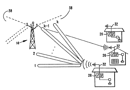
FIG. 6 illustrates "k" different scan angles for a directional antenna
associated with a fixed subscriber unit; j,
FIG. 7A illustrates a radio local loop system, prior to expansion of the
network;
FIG. 7B illustrates the radio local loop system of FIG. 7A after expansion
of the network; and
FIG. 8 is a flowchart showing one embodiment of the method of
reallocating subscriber units according to the present invention.
DETAILED DESCRIPTION OF THE PREI! ERRED EMBODIMENTS
FIG. 1 illustrates the configuration of a typical radio local loop (RLL)
system 10. As shown in FIG. 1, the coverage area associated with the RLL
system
ZO is divided into smaller, adjoining geographical areas, herein referred to
as radio
domains 12. FIG. 1 also illustrates that each radio domain 12 contains a
control
unit 34, wherein the control unit connects the corresponding radio domain with
a
public switch telephone network 40. In addition, the control unit 34
maintains,
among other things, a subscriber list 36, which identifies all of the fixed
subscriber
CA 02351350 2001-05-22 '
WO 00/31991 PCT/SE99l02074
-6-
units (FSU) assigned to the corresponding radio domain 12. Each radio domain
12
also includes one or more radio stations 14 which are linked to the control
unit 34,
typically over a wireline connection, and linked to a plurality of FSUs 26
over a
wireless or air interface. Although the RLL systern 10 is illustrated as
including
three radio domains 12, each of which, in turn, contain two radio stations 14,
it
will be understood that the RLL system may include more than or fewer than
three
radio domains, white each radio domain 12 may contain more than two radio
stations or as few as one radio station.
Each FSU 26, as stated above, communicates with a corresponding radio
station 14 over a wireless interface. Accordingly, each FSU 26 has one or more
transmit and receive antennas 32 which, in accordance with conventional
practice,
have been manually installed and/or adjusted so that they effectively point in
the
general direction of the corresponding radio station 14. The radio station 14
has a
1
plurality of antennas 16 which point radially outward and define a plurality
of
sectors 38a-d which face different directions. During a call, the FSU 26
communicates with a radio station 14 through a sector 38.
In addition, each FSU 26 is associated with one or more communication
devices, for example, cordless telephones 30, which are connected to the FSU
via
a socket 28. However, it will be understood by those skilled in the art that
the
communication devices may include devices other than cordless telephones, such
as computer terminals, fax machines and the like.
FIG. 2 depicts the basic components in a typical FSU 26. As shown in
FIG. 2, a typical FSU includes, among other features, a transceiver 20, a CPU
18,
a memory 22 and a channel selector 24, the functions of which will be
described in
greater detail below.
In order for a FSU 26 and a corresponding; radio station I4 to communicate
with one another over a wireless interface, a charnlel access scheme is
required,
such as the exemplary TDMA/TDD channel access scheme illustrated in FIG. 3.
As illustrated in FIG. 3, the exemplary TDMAITDD channel access scheme has
CA 02351350 2001-05-22
WO OOI31991 PCTISE99I02074
_'7_
ten frequency carriers, wherein each of the ten frequency carriers is divided
into
time frames, and wherein each time frame is further divided into a number of
time
slots, for example, 24 time slots. As the channel access scheme in FIG. 3 is a
TDD based scheme, one skilled in the art wilt appreciate that half, or
approximately half, of the time slots (e.g., 12 time slots) associated with
each of
the ten frequency carriers are set aside for downlinlt (i.e., from radio
station to
terminal) communications, while the remaining time slots associated with each
of
the ten frequency carriers are set aside for uplink (i..e., from terminal to
radio
station) communications.
In general, the ten frequency carriers are divided amongst the radio stations
14 in each radio domain 12. For example, if the r<~dio domain 12 has two radio
stations 14, the first radio station may be assigned frequency carriers 1-5
for use in
communicating with a number of corresponding FSUs, while the second radio
station may be assigned frequency carriers 6-10. Each of the various FSUs then
IS receive data and/or control information from a corresponding radio station
14
during an assigned downlink time slot and transmit data and/or control
information
to the corresponding radio station 14 during an assigned uplink time slot
associated
with one of the frequency carriers assigned to that radio station 14. It will
be
understood, however, that if the traffic load is relatively low, a FSU may be
permitted to communicate with the corresponding radio station 14 over more
than
one frequency carrier and/or more than one uplink: and downlink time slot.
Accordingly, the communications channel linking a particular FSU and a
particular
radio station 14 is defined by: i) an identifier code: that uniquely
identifies the radio
station 14 through which the FSU is communicating, ii) a frequency carrier
assigned to that radio station 14 over which the F:3U is communicating, and
iii) a
downlink and an uplink time slot associated with l:hat frequency carrier
during
which the FSU is communicating. The exemplar~r TDMAITDD channel access
scheme depicted in FIG. 3 is well known in the a~-t.
CA 02351350 2001-05-22
WO 00131991 PCTlSE99/02074
_g_
When a connection is first established between a FSU 26 and the RLL
system, it is preferable that the channel or channels exhibiting the best
possible
signal quality characteristics be assigned to support that connection. Of
course,
the same is true for existing connections as well. To help ensure that the
channel
or channels exhibiting the best possible signal quality characteristics are
assigned
to support new or existing connections, the CPU 1!3 in each FSU 26 will be
capable of continuously deriving a signal quality factor for each channel,
wherein
the signal quality factor may, for example, be derived as a function of one or
more
link parameters such as carrier-to-interference ratia~ (ClI), bit error rate
(BER),
frame erasure rate (FER), radio signal strength indicator (RSSI), or a
combination
thereof. Further, the values associated with the one or more link parameters
are
measured by the FSU 26 during those periods of time where the FSU 26 is not
transmitting or receiving data and/or control infornnation.
A
Once derived, the signal quality factors can be stored in the memory 22,
for example, in tabular form as illustrated in FIG. ~4. Then by continuously
updating the signal quality factor values stored in the memory 22, the channel
selector 24 in the FSU 26 can dynamically select the channel or channels
exhibiting the best signal quality characteristics when a connection is first
established or during an existing connection, if the signal quality associated
with
the channel or channels supporting the existing cormection degrade below an
acceptable level.
In copending U.S. Patent Application Serial No. 091 , which is
assigned to the same assignee as the present application, an improvement in
the
way RLL systems accomplish dynamic channel selection is described. In this
copending application, which is incorporated by reference herein, the
principle of
dynamic channel selection is extended by taking into consideration the FSU
antenna scan angle during the dynamic channel selection process, where scan
angle
is defined as the direction in which the peak radio frequency energy is being
transmitted and received relative to a reference direction.
CA 02351350 2001-05-22
W000/31991 PCT/SE99I02074
-9-
The present invention further extends the concept of dynamic channel
selection, as described in the above-identified copending U.S. patent
application.
More particularly, the present invention extends the: concept of dynamic
channel
selection by taking into consideration both the FSU antenna scan angle and the
radio station sector to facilitate the process of automatically reallocating
FSUs
when the RLL system is expanded. While the present invention is primarily
intended to be implemented in a fixed RLL system" it should not be limited
thereto.
FIG. 7A shows a RLL system 70, or a portion thereof, prior to expansion.
As shown, the RLL system 70 includes one radio domain 72 which contains one
radio station 74 to serve the FSU 76. The FSU 76 has an antenna 78 which
transmits and receives signals between the FSU 76 and one or more antennas 80
located at the radio station 74, wherein each of the one or more antennas 80
is
associated with a corresponding radio station sector 82a-d.
FIG. 7B, in contrast, illustrates the RLL system 70 of FIG. 7A after
expansion. As shown, the RLL system 70 now inc:Iudes a new radio domain 84
which contains two new radio stations 86 and 88. Expansion may be become
necessary when the number of FSUs becomes too 'large given the number of radio
domains and radio stations. Accordingly; the addition of new radio domains and
radio stations are needed to accommodate all of the FSUs and the resulting
traffic
capacity. Of course, when the RLL system 70 is Expanded, a certain number of
FSUs, for example FSU 76, may be reallocated to the new radio domain 84, if
doing so will result in better quality of service for the FSU.
In accordance with an exemplary embodiment of the present invention, the
CPU 18 in each FSU, for example, FSU 76, continuously derives a signal quality
factor for each potential communications channel, where a communications
channel linking the FSU 76 and a particular radio station, such as radio
station 74,
86 or 88, is now defined by: i) an identifier code that uniquely identifies
the radio
station, ii) a frequency carrier, iii) a downlink and an uplink time slot
associated
CA 02351350 2001-05-22
WO 00/31991 PCT/SE99I02074
-10-
with that frequency carrier, iv) the scan angle of thc~ FSU antenna 80, and v)
the
radio domain 72 and 84. The signal quality factor values measured for each
channel may be stored in the memory 22, for example, in tabular form as
illustrated in FIG. S. Appropriately, the table in F1~G. 5 contains one or
more
signal quality factor values for each frequency carrier, time slot, radio
station and
antenna scan angle combination, in each radio domain. By repeatedly updating
the
signal quality factor values for each channel, a dynamic picture of the radio-
frequency environment surrounding the FSU 76 is continuously maintained.
In order to derive a signal quality factor for each channel, that is, each
frequency carrier, time slot, radio station, radio domain and antenna scan
angle
combination, in accordance with a preferred embod.irnent of the present
invention,
the FSU antenna 80 is automatically swept through k different scan angles, as
illustrated in FIG. 6. As the antenna is swept through each of the k different
scan
angles, the FSU 76 measures the value of one or more link parameters such as
BER, FER, ClI, RSSI or the like, and therefrom, f~erives a signal quality
factor for
each channel. The signal quality factor values are then stored in the memory
22
and repeatedly updated, for example, 500 times per second, thereby creating a
more accurate, dynamic picture of the radio frequency environment surrounding
the FSU 76. In doing so, the FSU 76 can be dynamically reallocated to a new
radio domain during system expansion.
As mentioned, the antenna 80 is automatically swept through the k
different scan angles. This may be accomplished by mechanically sweeping a
rotatable antenna to each of the k different scan ankles, by electronically
sweeping
a phased-array antenna to each of the k different scan angles, or by selecting
each
one of a number of fixed directional antennas, wherein the boresight
associated
with each directional antenna is coincident with each of the k different scan
angles.
However, regardless of whether the automatic redirection of antenna scan angle
is
accomplished mechanically, electronically or through the selection of a number
of
directional antennas, it will be understood that the ;process of automatically
CA 02351350 2001-05-22
WO 00131991 PC'r/SE99/02074
-11-
sweeping through the k different scan angles, measuring the one or more link
parameters, and deriving a signal quality factor for each channel can be
controlled
through a dynamic channel selection algorithm residlent in, for example, the
memory 22.
If after system expansion, the FSU 76 determines, through the dynamic
channel allocation process, that the signal quality associated with the
communications channels corresponding to the one or more radio stations 86 or
88
in the new radio domain 84 are superior to the signal quality characteristics
associated with the communications channels corresponding to the radio station
74
in radio domain 72, an automatic FSU allocation procedure will be initiated.
FIG.
7B depicts the FSU 76 being reallocated to radio domain 84, through radio
station
86, as indicated by the solid line 90, after the FSU 76 has compared the
signal
quality factors associated with those communications channels corresponding to
radio stations 74, 86, and 88. The radio;,station 86 then, in turn,
automatically
IS selects the appropriate radio station sector through which the FSU 76 will
communicate during a call, for example, radio statiion sector 100a. The
identification code of the FSU 76 is then stored in 'the subscriber liat 96
maintained
in the control unit 98 of the new radio domain 84.
FIG. 8 shows the steps of an exemplary embodiment of the automatic
reallocation of a FSU 76 to a new radio domain 84~, as it relates to FIG. 7B.
The
block 805 indicates that the operator transmits an identification code
associated
with the new radio domain 84 to the FSU 76, wherein the identification code
includes geographical location information which indicates to the FSU the
direction of the new domain.
Next at block 810, the FSU 76 automaticalily adjusts the antenna 78 in the
general direction of the second radio domain 84. :ln performing these
adjustments,
the antenna 78 is swept through k different scan angles, either mechanically
or
electronically, and simultaneously transmits to and receives signals from the
radio
stations 86, 88 serving that domain. The block 8115 indicates that the FSU 76
sets
CA 02351350 2001-05-22 '
WO 00/31991 PCT/SE99l02074
-12-
the value of the scan angle "k" of the antenna 78 in its traffic channel
register 44.
Then the FSU at block 820 measures the value of one or more link parameters,
such as C/I, BER, FER, and RSSI at each possible: frequency, time slot, and
radio
station combination at the given scan angle and derives a signal quality
factor for
each communication channel based on the link par;~lneter values. The step at
block
820 is performed in accordance with the dynamic channel selection techniques
described in copending U.S. Patent Application 09l Next at block 825,
the FSU 76 can store the signal quality factors in the memory 22, as depicted
in
FIG. 5.
~ At decision block 830, it is determined whether or not the antenna 78 has
redirected itself through all of the k different scan angles. If so, the flow
moves to
block 840 where the FSU 76 compares the signal duality factors corresponding
to
the second radio domain 84 with those of the first radio domain 72; stored in
the
traffic channel register 44. Otherwise, the flow moves to block 835, wherein
the
FSU 76 incrementally increases the antenna scan angle. The flow then loops
back
to block 815 where the FSU 76 sets the value of tree antenna scan angle in the
traffic channel register 44 and continues to measure received signals from
radio
stations 86, 88 serving that second radio domain 8~4.
Having compared the signal quality factors of the first and second radio
domains 72 and 84, the flow proceeds to decision iblock 845. Here the FSU 76
determines whether the signal quality characteristics corresponding to the
second
radio domain 84 are superior to those corresponding to the first radio domain
72.
In one embodiment of the invention, the FSU 76 will make this determination if
it
identif es at least one communication channel between the FSU and a radio
station
86, 88 within the second radio domain 84 exhibiting superior signal quality
characteristics. In an alternative embodiment of W a invention, the FSU 76
uses a
statistical analysis procedure based on the signal quality factors for each
communication channel and determines whether the signal quality
characteristics of
CA 02351350 2001-05-22
WO 00/31991 PCTISE99/02074
-I3-
the second radio domain 84 are superior to those corresponding to the first
radio
domain 72.
If so, the flow moves to block 855, and the FSU 76 is reallocated to the
second radio domain 84 whereby the identification code of the FSU is added to
a
subscriber list 96 associated with the second radio domain and maintained at
the
corresponding central unit 98. Further, the control unit 94 associated with
the first
radio domain 72 will remove the identification coda of the FSU 76 from the
subscriber list 92. In an alternative embodiment of the present invention, the
control unit 94 associated with the first radio domain 72 will alter the
subscriber
IO list 92 to indicate that the FSU 76 is inactive with respect to the first
radio domain.
If the answer to this determination at decision block 845 is no, then the
flow moves to block 850 and no reallocation of the: FSU 76 to the second radio
domain 84 is made. Accordingly, the FSU 76 transmits a signal to the operator
indicating that it is not ready to accept az reallocation to the second radio
domain
84. The second control unit 98 will then flag the identification code of the
FSU 76
as being inactive in the subscriber list 96. The flow then proceeds to
decision
block 860.
Since the topology of the RLL system may change by adding one or more
radio domains, at decision block 860, it is determined whether or not the FSU
76
must check for other new radio domains. If so, the flow loops back to block
805
wherein the operator transmits an identification code associated with the
other new
radio domain (not shown) to the FSU 76. If the answer to this determination is
no,
then the flow loops back to decision block 860, and the FSU 76 continues to
check
for additional, new radio domains.
The present invention concerns a method and communication system for
automatically reallocating subscriber units when the radio system topology is
changed. This invention provides the advantages of automatic reallocation of
terminals to radio domains without expending the costly and time consuming
efforts needed to manually readjust each antenna. While the invention has been
CA 02351350 2001-05-22 '
WO 00/3t991 PCTISE99/02074
-14-
described in detail with reference to the preferred f:mbodiments thereof, it
will be
apparent to one skilled in the art that various chanl;es and modifications can
be
made and equivalents employed, without departing from the present invention.