Note: Descriptions are shown in the official language in which they were submitted.
CA 02359447 2008-08-20
FINGER OPERATED SWITCH FOR CONTROLLING
A SURGICAL HANDPIECE
1015
FJELD OF THE INVENTION
The invention generally relates to the field of medical or surgical
instruments
and, more particularly, to a novel finger-operated switch for controlling a
medical or surgical
20 handpiece.
-1-
CA 02359447 2008-08-20
r~ .
DESCRIPTION OF THE RELATED ART
Ultrasonic medical or surgical instruments have gained widespread acceptance
in the microsurgical field for use in the fragmentation and removal of body
tissue. A typical
ultrasonic instrument includes an ultrasonic transducer housed in a handpiece.
The
ultrasonic transducer is operable for converting electrical energy supplied
thereto into high-
velocity vibrational movements. The transducer-generated ultrasonic vibrations
are
transmitted to a surgically operative tip (such as a blade or a coagulator)
that is coupled
thereto.
U.S. Patent 5,026,387 issued to Thomas (the `387 patent), assigned to the
assignee of the present application) describes such an
ultrasonic surgical instrument. The ultrasonic instrument according to the
`387 patent
includes a "power on demand" control feature for causing a surgically sharp
cutting
instrument, such as a scalpel blade or other surgical instrument (e.g. a dull
cautery blade) to
automatically shift its operation between an unloaded or idle state and a
loaded or cutting
state, and vice versa, depending on whether the instrument is in contact with
a bodily tissue.
Figure 1 is a diagram illustrating a typical ultrasonic instrument known in
the
art in accordance with the `387 patent. As generally shown in Figure 1, a
harmonic generator
1 provides electrical energy to the handpiece 2 which imparts ultrasonic
longitudinal
movement to a surgical device, such as a sharp scalpel blade 3 which is used
for dissection
and/or coagulation. The harmonic generator I includes a liquid crystal display
device 4
indicating, e.g., the selected cutting power level as a percentage of the
maximum available
cutting power. The power selection level as well as other functions, such as
coagulation
-2-
CA 02359447 2001-10-17
= w
mode duration, may also be selected by pushing buttons 5 in response to a menu
appearing
on the display 4. The handpiece 2 is connected to the harmonic generator 1 by
a coaxial
cable 8. As illustrated in more detail in Figure ]a and the `387 patent, the
ultrasonic
handpiece 2 houses an ultrasonic system for converting electrical energy to
mechanical
energy that results in longitudinal vibrational motion. The ultrasonic system
comprises a
transducer 9, a mounting device 10 and a surgical device 11 such as the
scalpel blade and
holder. The transducer 9 includes a stack of ceramic piezoelectric elements 12
with a
motionless node at the center of the stack sandwiched between two aluminum
cylinders 13
and 14. The transducer 9 is fixed to the mounting device 10 in a permanent
manner. In turn,
the mounting device 10 is attached to the housing at another motionless node
by an integral
ring 15. The mounting device 10, transducer 9 and the surgical device 11 are
designed and
fabricated to oscillate at the same resonant frequency, with each element
tuned accordingly
such that the resulting length of each such element is one-half wavelength.
Expansion of the
piezoelectric ceramic elements 12 results in the initiation of motion in the
acoustic system
of the transducer 9.
Detachably connected to the harmonic generator I is a foot switch 6 for
causing activation of the device in a coagulation operation mode. A switch 6a
is
incorporated in the handpiece 2. However, the switch 6a as found in the art
includes
shortcomings such as a high risk of inadvertent activation and deactivation.
Long-term
operation results in fatigue in the finger of the human operator of the
handpiece 2.
Therefore, there is a general need in the art for an improved switch for use
with an ultrasonic surgical handpiece. In particular, a need exists for a
switch in an
-3-
CA 02359447 2009-08-24
ultrasonic surgical handpiece that is easy-to-operate, reduces the risk of
inadvertent
activation/deactivation, and reduces fatigue in the finger of the human
operator.
SUMMARY OF THE INVENTION
According to the invention, a finger-operated switch for activating and
operating an
ultrasonic surgical handpiece is provided. The power output of the surgical
handpiece is
responsive and proportional (linearly, nonlinearly proportional or in terms of
a step function)
to the pressure applied to the finger-operated switch. The finger-operated
switch may
include, but is not limited to: (1) electromechanical switches; (2) force
sensitive resistors
whose resistance is proportional to the force applied by the finger of the
human operator of
the surgical handpiece; (3) force sensitive capacitors whose capacitance is
proportional to
the pressure, deflection or compression of the insulation layer between two
electrodes or is
proportional to the spacing between the two conductive layers; (4) strain
gauges mounted
underneath or integral to the housing of the surgical handpiece such that the
pressure applied
thereto results in an output change in the strain gauges; (5) magnets or
ferromagnets encased
or embedded in an elastomer with a sensor inside the surgical handpiece that
detects the
field strength of the magnet and monitors changes relative to the force
applied to the
handpiece housing; and (6) piezo film or piezo ceramic material whose charge
or voltage is
proportional to the force applied.
In some aspects, there is provided a system for implementing surgical
procedures
comprising:
an ultrasonic surgical handpiece having an end-effector;
a generator console for controlling the handpiece;
an electrical connection connecting the handpiece and the console, wherein
the console sends a drive current to drive the handpiece which imparts
ultrasonic
longitudinal movement to the end-effector; and
a finger-operated switch provided on a housing of the handpiece, the switch
activating the handpiece at a first power level if a sensor monitored pressure
value on the
-4-
CA 02359447 2009-08-24
switch reaches a high threshold, deactivating the handpiece if the sensor
monitored pressure
value reaches a low threshold, and provides its switching functionality
according to a
lagging effect as the monitored pressure on the switch is changed, and the
handpiece
operating at a level proportional to the sensor monitored pressure value on
the finger-
operated switch.
In some aspects, there is provided a system for implementing surgical
procedures
comprising:
an ultrasonic surgical handpiece having an end-effector;
a generator console for controlling the handpiece;
an electrical connection connecting the handpiece and the console, wherein
the console sends a drive current to drive the handpiece which imparts
ultrasonic
longitudinal movement to the end-effector; and
a finger-operated switch provided on a housing of the handpiece, the switch
activating the handpiece at a first power level and deactivating the handpiece
if a low
threshold is reached, and provides its switching functionality according to a
lagging effect as
a monitored pressure on the switch is changed, and the handpiece operating at
a level
proportional to a sensor monitored pressure value on the finger-operated
switch.
In some aspects, there is provided an ultrasonic surgical handpiece having a
housing
with a finger-operated switch located thereon, the switch having a sensor for
monitoring
pressure thereon so that the handpiece is placed in an operative mode when the
sensor
monitors a pressure above a first threshold and is placed in another operative
mode when the
pressure is below a second threshold, and provides its switching functionality
according to a
lagging effect as the monitored pressure on the switch is changed, and the
handpiece
operates at a level proportional to a pressure value on the finger-operated
switch that is
monitored by the sensor.
-4a-
CA 02359447 2001-10-17
s e
BRIEF DESCRIPTION OF THE DRAWINGS
These and other features, aspects, and advantages of the invention will
become more readily apparent with reference to the following detailed
description of a
presently preferred, but nonetheless illustrative, embodiment when read in
conjunction with
the accompanying drawings. The drawings referred to herein will be understood
as not being
drawn to scale, except if specifically noted, the emphasis instead being
placed upon
illustrating the principles of the invention. In the accompanying drawings:
Figure 1 is a diagram illustrating an ultrasonic surgical system known in the
art;
Figure la is a diagram illustrating the interior of the ultrasonic surgical
handpiece of the surgical system shown in Figure I and known in the art;
Figure 2 is an illustration of a generator console for an ultrasonic surgical
cutting and hemostasis system according to the invention;
Figure 2a is a schematic view of a cross section through the ultrasonic
scalpel
handpiece of the system of Figure 2;
Figure 2b is longitudinal cross-sectional view of an exemplary button switch
according to the invention;
Figure 3a is a diagram illustrating a housing deflection embodiment of the
switch for controlling the ultrasonic surgical handpiece according to the
invention;
Figure 3b is a diagram illustrating a pressure button embodiment ofthe switch
for controlling the ultrasonic surgical handpiece according to the invention;
-5-
CA 02359447 2001-10-17
Figures 3c, 3d, 3e and 3f are diagrams illustrating various magnet button
embodiments of the switch for controlling the ultrasonic surgical handpiece
according to the
invention;
Figures 4a and 4b are diagrams illustrating the various power levels of
operation for the ultrasonic surgical handpiece controlled by the switch
according to the
invention;
Figure 5 is a flow diagram generally illustrating the method according to the
invention for controlling the ultrasonic surgical handpiece using a switch;
Figures 6, 6b and 6c are diagrams illustrating a ring embodiment (and cross-
sectional views thereof) for the switch for the surgical handpiece according
to the invention;
Figures 7a through 7i are diagrams showing partial cross sectional views of
various embodiments of the ring switch for the ultrasonic surgical handpiece
according to
the invention; and
Figures 8a, 9, 9a, 10, 10a, l Ob, 11 and 12 are diagrams illustrating various
embodiments for the ring switch with activation zones for the ultrasonic
surgical handpiece
according to the invention.
DETAILED DESCRIPTION OF THE PREFERRED EMBODIMENTS
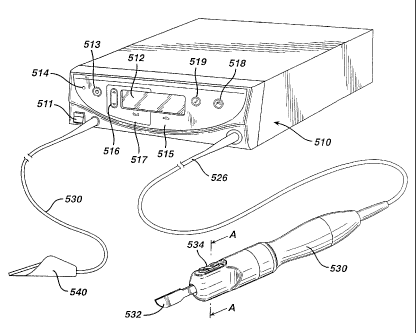
Figure 2 is an illustration of a system for implementing surgical procedures
according to the invention. By means of a first set of wires in cable 526,
electrical energy,
i.e., drive current, is sent from the generator console 510 to a handpiece 530
where it imparts
ultrasonic longitudinal movement to a surgical device or end effect or, such
as a sharp scalpel
-6-
CA 02359447 2001-10-17
blade 532. This blade can be used for simultaneous dissection and
cauterization of tissue.
The supply of ultrasonic current to the handpiece 530 may be under the control
of a distally
located switch 534 located on the handpiece, which is connected to the
generator in console
510 via wires in cable 526. The generator may also be controlled by a foot
switch 540,
which is connected to the console 510 by another cable 550. Thus, in use a
surgeon may
apply an ultrasonic electrical signal to the hand piece, causing the blade to
vibrate
longitudinally at an ultrasonic frequency, by operating the switch 534 on the
handpiece with
his finger, or by operating the foot switch 540 with his foot.
The generator console 510 includes a liquid crystal display device 512, which
can be used for indicating the selected cutting power level in various means
such, as
percentage of maximum cutting power or numerical power levels associated with
cutting
power. The liquid crystal display device 512 can also be utilized to display
other parameters
of the system. Power switch 511 is used to turn on the unit. While it is
warming up, the
"standby" light 513 is illuminated. When it is ready for operation, the
"ready" indicator 514
is illuminated and the standby light goes out. If the unit is to supply
maximum power, the
MAX button 515 is depressed. If a lesser power is desired, the MIN button 517
is activated.
This automatically deactivates the MAX button. The level of power when MIN is
active is
set by button 516.
When power is applied to the ultrasonic hand piece by operation of either
switch 534 or 540, the assembly will cause the end effector (surgical scalpel
or blade) to
vibrate longitudinally at approximately 55.5 kHz (or about 25 kHz in another
embodiment),
and the amount of longitudinal movement will vary proportionately with the
amount of
-7-
CA 02359447 2001-10-17
driving power (current) applied, as adjustably selected by the user. When
relatively high
cutting power is applied, the blade is designed to move longitudinally in the
range of about
40 to 100 microns at the ultrasonic vibrational rate. Such ultrasonic
vibration of the blade
will generate heat as the blade contacts tissue, i.e., the acceleration of the
blade through the
tissue converts the mechanical energy of the moving blade to thermal energy in
a very narrow
and localized area. This localized heat creates a narrow zone of coagulation,
which will
reduce or eliminate bleeding in small vessels, such as those less than one
millimeter in
diameter. The cutting efficiency of the blade, as well as the degree of
hemostasis, will vary
with the level of driving power applied, the cutting rate of the surgeon, the
nature of the
tissue type and the vascularity of the tissue.
As illustrated in more detail in Figure 2a, the ultrasonic handpiece 530
houses
a piezoelectric transducer 536 for converting electrical energy to mechanical
energy that
results in longitudinal vibrational motion of the ends of the transducer. The
transducer 536
is in the form of a stack of ceramic piezoelectric elements with a motion null
point located
at some point along the stack. The transducer stack is mounted between two
cylinders 531
and 533. In addition a cylinder 535 is attached to cylinder 533, which in turn
is mounted to
the housing at another motion null point 537. A hom 538 is also attached to
the null point
on one side and to a coupler 539 on the other side. Blade 532 is fixed to the
coupler 539.
As a result, the blade 532 will vibrate in the longitudinal direction at an
ultrasonic frequency
rate with the transducer 536. The ends of the transducer achieve maximum
motion with a
portion of the stack constituting a motionless node, when the transducer is
driven with
maximum current at the transducers' resonant frequency. However, the current
providing the
-8-
CA 02359447 2008-08-20
maximum motion will vary with each hand piece and is a value stored in the non-
volatile
memory of the hand piece so the system can use it.
The parts of the handpiece are designed such that the combination will
oscillate at the same resonant frequency. In particular, the elements are
tuned such that the
resulting length of each such element is one-half wavelength. Longitudinal
back and forth
motion is amplified as the diameter closer to the blade 532 of the acoustical
mounting horn
538 decreases. Thus, the horn 538 as well as the blade/coupler are shaped and
dimensioned
so as to amplify blade motion and provide harmonic vibration in resonance with
the rest of
the acoustic system, which produces the maximum back and forth motion of the
end of the
acoustical mounting horn 538 close to the blade 532. A motion from 20 to 25
microns at the
transducer stack is amplified by the horn 538 into blade movement of about 40
to 100
microns.
Figure 2b is a more detailed longitudinal cross-sectional view of an exemplary
button switch according to the invention. This design, as well as others
disclosed herein,
allows for operation of the hand pieces in various modes, and is also
described in related
U.S. Patent No. 6,623,500, commonly assigned to the same assignee as
the present application, having the title RING CONTACT FOR ROTATABLE
CONNECTION OF SWITCH ASSEMBLY FOR USE IN AN ULTRASONIC SURGICAL
SYSTEM and filed on October 20, 2000, The
switch for use with an ultrasonic surgical handpiece according to the
invention includes two
independent switches under generally the same elastomer or flexible thin
metallic skin with
a middle recess for resting a finger of a human operator. The middle recess
serves as a tactile
-9-
CA 02359447 2001-10-17
reference point, as the blade and handpiece are non-symmetrically configured,
for the human
operator which avoids inadvertent activation or deactivation. In addition, the
middle recess
provides a safe, convenient spot for the human operator to grasp the handpiece
and the
switch without inadvertently activating the switch. The switch is also
ergonomically
designed and tested to be comfortably grasping for small or big hands of any
human operator
of the handpiece.
Referring to Figure 2b, the ultrasonic surgical handpiece according to the
invention provides a switch that includes a pair of switch button members 270,
detachably
secured within the button sections 214, which are about 180 apart to permit
convenient
grasping of the handpiece yet avoid inadvertent activation or deactivation.
Each switch
button member 270 has an upper surface 272 and an opposing lower surface 274
with the
lower surface 274 seating against the outer shell 201. First and second posts
276, 278,
respectively, extend outwardly away from the lower surface 274 of the switch
button member
270. The first and second posts 276, 278 are spaced apart from one another
with a center
traverse wall being formed therebetween. The upper surface 272 includes a
first raised
section 282 and a second raised section 284 spaced therefrom with a center
recessed section
286 being formed therebetween. The upper surface 272 is thus slightly beveled
as the switch
button member 270 transitions from the center recessed section 286 to the
first and second
raised sections 282, 284. In the illustrated embodiment, the first post 276 is
disposed
generally below the first raised-section 282 and the second post 278 is
disposed generally
below the second raised section 284 so that when a user presses downwardly
upon the first
raised section 282, the first post 276 is also directed downward. Similarly,
when the switch
-10-
CA 02359447 2001-10-17
is pressed downwardly upon the second raised section 284, the second post 278
is directed
downward. In another embodiment according to the invention, the switch is a
dome switch
which includes a dome of a thin metallic skin that collapses downward as
pressure is applied
thereto.
The switch button members 270 are designed to act as a depressable switch
button for selectively causing activation of the ultrasonic surgical handpiece
according to the
invention. The switch button members 270 are formed of suitable materials,
such as plastic
materials, and preferably the switch button members 270 are formed of a
resilient plastic
material. In one exemplary embodiment, the switch button members 270 are
formed of
silicon which permits the members to be sufficiently resilient enough so that
they may be
fitted and secured within the button sections 214 to seal internally and also
provide an
engagement surface for a finger or thumb of a human operator during operation
of the
handpiece. In one aspect of the present invention, the contour of the switch
button member
270 permits a fingertip of a human operator to easily rest between the first
and second raised
sections 282 and 284. In other words, the finger tip or thumb of a human
operator seats and
rests within the center recessed section 286 without actuating the switch
mechanism. The
switch button members 270 are disposed within the button sections 214. The
switch button
members 270 are spaced about 180 from one another. A pair of fasteners 300
are
positioned beneath the center traverse wall. Each button section 214 formed in
the outer
shell 201 contains openings formed therein and spaced apart from one another
for receiving
the first and second posts 276 and 278 of the switch button member 270. The
exemplary
switch mechanism is an electro-mechanical switch that is depressable for
activation and,
-11-
CA 02359447 2001-10-17
according to the present invention, two switch button members 270 form, at
least in part, the
switch. Each switch button member 270 has two switch sites. For example, the
first raised
section 282 and the first post 276 are associated with a first switch site and
the second raised
section 284 and the second post 278 are associated with a second switch site.
Preferably, the
first switch site of one switch button member 270 is generally the same as the
first switch
setting of the other switch button member 270 disposed about 180 therefrom.
In one
exemplary embodiment, the first switch site is a maximum power setting (MAX)
and the
second switch setting is an intermediate power setting which can include a
minimum (MIN).
It will be understood that the opposite may equally be true, in that the first
switch setting may
be designed for causing the transmission of intermediate power to the
handpiece according
to the invention and the second switch setting will then cause the
transmission of maximum
power to the handpiece.
Distally placing the switch on the handpiece according to the invention
provides significant advantages over the prior art. As switches in the art are
placed on the
non-distal end (e.g., medial or proximal end) of the handpiece, blade control
becomes
ineffective since operating the blade with a switch proximally positioned on
the handpiece
creates substantially uncontrollable jitter when using the blade for cutting
or coagulation on
a tissue. Pressing the switches proximally located on the handpiece has
negative effects and
disrupts blade positioning on the tissue. Such is particularly inconvenient
for performing
surgery and burdensome for a human operator in controlling the handpiece.
Positioning the
switches on the distal end of the handpiece significantly reduces the
occurrence of blade jitter
and generally improves operational control of the haridpiece by the human
operator.
-12-
CA 02359447 2008-08-20
The switch according to the invention is configured on the distal end of the
handpiece, to permit accurate blade control, handpiece handling and to
conveniently operate
the switches without jitter of the blade, with the scalpel blade 532 which is
screwed onto the
handpiece and rotatable. The switch according to the invention, in relation
with the blade
532, is configured so that the switch is generally aligned by a human operator
with the blade
as it is rotated or indexed to a particular blade symmetry. The alignment by
the human
operator (or user alignment) can be incremental (using indents or detents),
continuous or
indexed to particular symmetries. The switch can also be generally aligned
with the rotating
blade with a particular symmetry, depending on the configuration of the
handpiece and needs
of the human operator for cutting or coagulation. Other embodiments of the
switch
according to the invention include a switch with a single button member, metal
dome
switches whose dome collapses for contacting a circuitry on a printed circuit.
board (PCB),
which is described in related U.S. Patent No. 6,623,500, commonly
assigned to the same assignee as the present application, having the title
RING CONTACT
FOR ROTATABLE CONNECTION OF SWITCH ASSEMBLY FOR USE IN AN
ULTRASONIC SURGICAL SYSTEM and filed on October 20, 2000.
The switch according to the invention can also be used for controlling
functions in the generator console 510 including initiating diagnostic
functions on the
handpiece, and implementing a standby mode. In a particular embodiment
according to the
invention, the standby mode of operating the handpiece, which renders the
switch inoperable,
-13-
CA 02359447 2001-10-17
is activated by applying pressure to both buttons of the switch at generally
the same time.
The standby mode is subsequently deactivated by doing the same, i.e., by
applying pressure
to both buttons of the switch at generally the same time.
Figure 3a is a cross-sectional view (taken at A-A of Figure 2) that
illustrates
a housing deflection embodiment of the switch for an ultrasonic surgical
handpiece
according to the invention. This one-push button design, as well as others
disclosed herein,
allows for operation of the hand pieces in various modes. The switch according
to the
housing deflection embodiment as shown in Figure 3a includes a pressure sensor
31 mounted
inside the housing 33 of the ultrasonic handpiece 32 where it is relatively
protected from the
environment. The sensor 31, located on the internal side of a thin wall area
36 of the
handpiece housing 33, detects pressure 30 applied by a finger of a human
operator of the
handpiece 32. The sensor 31 can be, but is not limited to, an electro-
mechanical switch, a
strain gauge, a pressure sensitive resistor/sensor combination, a hall affect
device/magnet
combination, reed switch/magnet combination, a piezo element, or a capacitance
sensor
which detects the force applied to the thin wall area 36. As finger pressure
30 is applied to
the thin wall 36, the portion of the handpiece housing 33 at the thin wall 36
deflects, which
is detected by the sensor 31. The sensor 31 outputs a response signal to the
handpiece. This
signal is conveyed through cable 526 to a detection circuit in the generator
console 510 that
controls the application of power to the transducers in the handpiece in
response thereto.
The switch according to the invention provides multi-level activation and
operation via the thin wall area 36, where various levels of applied pressure
determine the
mode of operation for the handpiece 32. In accordance with the magnitude of
the finger
-14-
CA 02359447 2001-10-17
pressure 30, the output from the sensor 31 causes the handpiece 32 to be "on"
or "off' or
more particularly, operating with a power level proportional to the finger
pressure 30 as
applied to the thin wall 36. For example, after initial activation of the
handpiece 32 ("on"),
a very low applied pressure 30 enables low power level operation of the
handpiece 32. A
somewhat higher applied pressure 30 enables higher power level operation of
the handpiece
32, without excessive finger pressure fatigue for the human operator of the
handpiece 32.
Figure 3b is a cross-sectional view (taken at A-A of Figure 2) that
illustrates
a pressure button embodiment of the switch for an ultrasonic surgical
handpiece according
to the invention. According to the pressure button embodiment which is a one-
push button
design, the handpiece 32 includes a button 37 mounted on a button support 38
on the exterior
of the handpiece housing 33. A pressure sensor 34 is located inside the
handpiece housing
33 and is separated from the button 37 by a thin wall area 36 of the handpiece
housing 33.
When finger pressure 30 is applied to the button 37, the thin wall area 36 is
deflected and a
concentrated, focused pressure is detected by the pressure sensor 34. The
thumbnail-like
design of the button having a pointy end 37A towards the pressure sensor 34
ensures
transmission of concentrated pressure to the pressure sensor 34, which
requires less effort
by a human operator during application of pressure to the button 37. The
pressure sensor 34
detects the force applied to the thin wall area 36 and outputs a response
signal to the
handpiece 32 which transmits it to a detection circuit in the generator
console 510. The
switch according to the invention provides multi-level activation and
operation via the thin
wall area 36, where various levels of applied pressure determine the mode of
operation for
the handpiece 32. In accordance with the magnitude of the finger pressure 30,
the output
-15-
CA 02359447 2001-10-17
from the sensor 31 causes the handpiece 32 to be "on" or "off' or more
particularly,
operating with a power level proportional to the finger pressure 30 as
applied.
Figure 3c is a cross-sectional view (taken at A-A of Figure 2) that
illustrates
a magnet button embodiment of the switch for an ultrasonic surgical handpiece
32 according
to the invention. According to this embodiment which is a one-push button
design, the
handpiece 32 includes an elastomeric pad 39 with a magnet 40 (or,
ferromagnetic element,
metallic element, or coil) embedded therein. A sensor 35 is located inside the
handpiece
housing 33 and detects the field strength of the magnet. Sensor 35 monitors
changes in field
strength related to the force applied to the handpiece housing 33. The sensor
35 can be, but
is not limited to, a reed switch; a hall effect device; or an inductance,
proximity, or
capacitance sensor, which responds to the relative position of a neighboring
piece of magnet
or ferromagnet or material (e.g., magnet 40). As finger pressure 30 is applied
to the
elastomeric pad 39, the magnet 40 moves closer to the sensor 35. The switch
according to
the invention provides multi-level activation and operation, where various
levels of applied
pressure determine the mode of operation for the handpiece 32. Depending on
the magnitude
of the finger pressure 30, the output from the sensor 35 causes the handpiece
32 to be "on"
or "off 'or more particularly to operate with a power level proportional to
the finger pressure
30 applied.
Figure 3d is a partial cross-sectional view (taken at A-A of Figure 2) that
illustrates another magnet button embodiment of the switch for an ultrasonic
surgical
handpiece 32 according to the invention. Figure 3d is similar to Figure 3c,
except that it is
greatly enlarged and the magnet 41 is embedded in a slide button 48 as opposed
to the
-16-
CA 02359447 2001-10-17
elastomeric pad 39 of Figure 3c. According to this particular embodiment, the
handpiece 32
includes a slide button 48 slidably attached on the outside of the handpiece
housing 33 with
a magnet 41 (or, ferromagnetic element, metallic element, or coil) embedded
therein. A
sensor 44 is located inside the handpiece housing 33 and detects the field
strength of the
magnet. In particular, sensor 44 monitors changes in the magnet's field
strength related to
the force applied to the handpiece housing slide button. The sensor 44 can be,
but is not
limited to, a reed switch; a hall effect device; or an inductance, proximity,
or capacitance
sensor, which responds to the relative position of a neighboring piece, of
magnet or
ferromagnet (e.g., magnet 41). As finger pressure 30 is applied to the slide
button 48, the
embedded magnet 41 moves closer to the sensor 44. If desired, slide button 48
can be
attached to a spring which tends to restore it to its initial position. As a
result, the position
of slide button 48 is proportional to the amount of force applied, and not
just simply the
application of some force, for a period of time.
The switch according to the embodiment of Figure 3d provides multi-level
activation and operation, where various levels of applied pressure on the
application of
pressure for various periods determine the mode of operation for the handpiece
32.
Depending on the magnitude of the finger pressure 30 or where the switch is
when the
pressure is released (assuming no spring return), the output from the sensor
44 causes the
handpiece 32 to be "on" or "off' or more particularly, operating with a power
level
proportional to the position or finger pressure 30 as applied.
Figure 3e is a partial cross sectional view (taken at A-A of Figure 2) that
illustrates another magnet button embodiment of the switch for an ultrasonic
surgical
-17-
CA 02359447 2001-10-17
handpiece 32 according to the invention. Figure 3e is similar to Figure 3d,
except that the
magnet 42 is embedded in a lever 49 as opposed to the slide button 48 of
Figure 3d.
According to this particular embodiment, the handpiece 32 has the lever 49
extending from
the outside to the inside of the handpiece housing 33, with a magnet 42 (or,
ferromagnetic
element, metallic element, or coil) embedded therein. The lever 49 is made of
an elastic
material and responds to finger pressure 30 so as to be bendable to the left
or right. Two
sensors 45 and 46 are located inside the handpiece housing 33 that detect the
field strength
of the magnet and monitor changes therein relative to the force applied to the
lever 49. The
sensors 45 and 46 can be, but are not limited to a reed switch; a hall effect
device; or an
inductance, proximity, or capacitance sensor which responds to the relative
position of a
neighboring piece of magnet or ferromagnet (e.g., magnet 42) as plastic lever
49 is bent. As
finger pressure 30 is applied to the lever 49, the embedded magnet 42 moves
closer to either
sensor 45 or sensor 46. The switch according to the invention thus provides
multi-level
activation and operation, where various levels of applied pressure and the
direction of that
pressure on lever 49 determine the mode of operation for the handpiece 32.
Depending on.
the magnitude and direction of the finger pressure 30, the output from the
sensor 45 causes
the handpiece 32 to be "on" (if the lever 49 is pressed toward the sensor 45
and against the
handpiece housing 33 fully), or operating with a power level proportional to
the finger
pressure 30 as applied. Similarly, depending on the magnitude of the finger
pressure 30, the
output from the sensor 46 causes the handpiece 32 to be "off' (if the lever 49
is pressed
toward the sensor 46 and against the handpiece housing 33 fully), or operating
with a power
level proportional to the finger pressure 30 as applied.
-18-
CA 02359447 2001-10-17
As an alternative, if no pressure is applied and sensors 45, 46 receive
relatively equal field strengths, the handpiece can be off. It can then
operate in one mode
(e.g. cutting) as different levels, as the lever is pressed toward sensor 45
and in a different
mode (e.g. coagulation) at different levels as the lever is pressed towards
sensor 46.
Figure 3f is a cross sectional view (taken at A-A of Figure 2) that
illustrates
another magnet button embodiment of the switch for an ultrasonic surgical
handpiece 32
according to the invention. Figure 3f is similar to Figure 3c, except that the
magnet 43 is
embedded in an elastic ring 50 as opposed to the elastomeric pad 39 of Figure
3c. A sensor
47 is located inside the handpiece housing 33 that detects the field strength
of the magnet 43
and monitors changes in the field strength relative to the force applied to
the ring 50 toward
the housing 33. The sensor 47 can be, but is not limited to a reed switch; a
hall effect device;
or an inductance, proximity, or capacitance sensor which responds to the
relative position of
a neighboring piece of magnet or ferromagnet (e.g., magnet 43). As finger
pressure is
applied to the ring 50, the embedded magnet 43 moves closer to the sensor 47.
The switch
according to the invention provides multi-level activation and operation,
where various levels
of applied pressure on the elastic ring 50 determine the mode of operation for
the handpiece
32. Depending on the magnitude of the finger pressure, the output from the
sensor 47 causes
the handpiece 32 to be "on" or "off" or more particularly, operating with a
power level
proportional to the finger pressure as applied.
The switch according to the invention, as described herein and shown in the
accompanying figures, provides multi-level activation and operation at
different power
levels, where various levels of applied pressure determine the mode of
operation for the
-19-
CA 02359447 2001-10-17
ultrasonic surgical handpiece. Figure 4A is a diagram that illustrates the
operation of a single
power level embodiment of the ultrasonic surgical handpiece having a switch
according to
the invention. The relationship of finger pressure applied to the switch and
the power level
of the ultrasonic surgical handpiece referenced by time is shown. A high
finger pressure is
required to activate the handpiece at time to. Once activated, the handpiece
operates at
power level 1. Thereafter, only a sufficiently high finger pressure (higher
than the "low"
finger pressure as marked) is needed to keep the handpiece operative at power
level 1. Once
the finger pressure applied to the switch equals or falls below the "low"
threshold at time t 1,
the handpiece turns "off' and ceases to receive output power.
Figure 4b is a diagram that illustrates the operation of a dual power level
embodiment of the ultrasonic surgical handpiece having a switch according to
the invention.
The relationship of finger pressure applied to the switch and the power level
of the ultrasonic
surgical handpiece referenced by time is shown. A high finger pressure is
required to
activate the handpiece at time t0. Once activated, the handpiece operates at
power level 1.
Once the finger pressure applied to the switch equals or falls below the
"medium" threshold
at time ti, th : handpiece operates at power level 2. Thereafter, if the
finger pressure equals
to or falls below the "low" threshold at time t2, the handpiece turns "off"
and ceases to
receive output power.
Figures 4a and 4b merely illustrate two embodiments, i.e., the single power
level and the dual power level embodiments, respectively, ofthe multi-level
power operation
-20-
CA 02359447 2001-10-17
r
for the ultrasonic surgical handpiece having a pressure sensitive switch
according to the
invention. Other multi-level embodiments, e.g., three-level, four-level, etc.,
are also
considered to be within the scope and spirit of the present invention.
Accordingly, the invention provides a method for controlling an ultrasonic
surgical handpiece using a switch located on the housing of the handpiece,
which comprises
the steps of (1) monitoring the pressure applied to the housing a lever or
ring compressors
the switch; (2) activating the surgical handpiece at a high power level if the
monitored
pressure reaches a high threshold; (3) operating the surgical handpiece at a
corresponding
intermediate power level if the monitored pressure reaches a specific
intermediate threshold
below the high threshold; and (4) deactivating the surgical handpiece if the
monitored
pressure is below a low threshold which is less than the specific intermediate
threshold. The
finger-operated switch includes, but is not limited to, (a) an electro-
mechanical switch, (b)
force sensitive resistors whose resistance is proportional to the force
applied by the finger of
the human operator of the surgical handpiece; (c) force sensitive capacitors
whose
capacitance is proportional to the pressure, deflection or compression of the
insulation layer
between two electrodes or is proportional to the spacing between the two
conductive layers;
(d) strain gauges mounted underneath or integral with the housing of the
surgical handpiece
such that the pressure applied thereto results in an output change in the
strain gauges; (e)
magnets or ferromagnets encased or embedded in an elastomer with a sensor
inside the
surgical handpiece that detects the field strength of the magnet and monitors
changes relative
to the force applied to the handpiece housing; and (f) piezo film or piezo
ceramic materials
whose charge or voltage is proportional to the force applied.
-21-
CA 02359447 2001-10-17
Figure 5 is a flow diagram that illustrates the method according to the
invention for controlling the ultrasonic surgical handpiece using a pressure-
sensitive switch.
In step 51, the pressure applied to the housing of the surgical handpiece,
elastomer material
mounted on the housing, an elastic lever, or an elastic ring is monitored. The
monitored
pressure is tested against a high threshold (step 52). If the monitored
pressured does not
reach the high threshold, the control flow reverts to step 51 which continues
the monitoring
of the pressure applied to the housing of the surgical handpiece. If the
monitored pressure
reaches the high threshold, the surgical handpiece is activated to operate at
a first power level
(step 53). Ifthe surgical handpiece does not have multi-level operational
capability (step 54),
then control flow goes to step 57 and the monitored pressure is tested against
a low
threshold. If the monitored pressure reaches the low threshold, then the
surgical handpiece
is deactivated (step 58). This operation could also be based on a single
threshold. In
particular, if it is determined that the pressure has exceeded a minimum
level, the power is
turned on full and remains there until it is determined that the pressure has
fallen below the
single minimum threshold.
If the surgical handpiece can operate at multiple power levels (step 54), then
in the method of Figure 4, the monitored pressure: is tested against a
plurality of specific
thresholds (step 55). If the monitored pressure reaches a specific
intermediate threshold, then
the surgical handpiece operates at a power level corresponding to that
specific threshold (step
56). In step 57, if the monitored pressure reaches the low threshold, then the
surgical
-22-
CA 02359447 2001-10-17
handpiece is deactivated. If the monitored pressure has not yet reach the low
threshold, the
control flow reverts back to step 55 and the surgical handpiece continues to
operate at
multiple power levels.
When the system has multiple thresholds, it can step down from a minium
various power levels as the pressure is released. Alternatively it can turn on
at a minimum
level and step up to higher levels of power as the pressure is increased.
In a further embodiment, the switch according to the invention includes a
sensor that is flat and tape-like. This type of sensor is made of piezo-
electric material or a
pressure-sensitive resistor (or resistor tape). Such a flat tape-like sensor
provides a very low
profile sensing means that is relatively easily mounted on or in a surgical
handpiece. With
the flat tape-like sensor, the switch is configured as an "active zone" on or
around the
surgical handpiece for activating and controlling the handpiece. The switch is
activated
when the surgeon's finger is on or applies pressure., to the active zone.
Figure 6 is a diagram that illustrates a ring embodiment for the switch for
the
handpiece according to the invention. A harmonic generator 510, illustrated in
Figure 2,
provides electrical energy to the handpiece 62 which imparts ultrasonic
longitudinal
movement to a surgical device, such as a sharp scalpel blade 603 used for
dissection or
coagulation. The handpiece 62 is connected to the harmonic generator 510 by
the coaxial
cable 26X. The ring switch 60a is a ring-like circumferential appendage on the
handpiece
62, located near the distal end thereof. The handpiece 62 is activated when
pressured is
applied, e.g, by a finger of a human operator of the handpiece 62, to the side
wall of the
switch 60a. The mode of activation (e.g., cutting or coagulation) is
determined by which side
-23-
CA 02359447 2001-10-17
of the ring switch 60a is pressed upon. Pressure may be applied in a direction
that is not
perpendicular to the handpiece 62 and still activate it. Pressure applied to
the top of the ring
switch 60a which is perpendicular to the handpiece 62, depending on the
particular
embodiment, can lead to a number of functions. That is, the pressure applied
to the top of
the ring switch 60a may be ignored on the one hand, invoke a third mode of
operation other
than cutting and coagulation, or default to one of the two selectable modes of
operation. For
example, when the ring switch 60a is pressed, the base of the ring switch 60a
applies
pressure to one of several pressure-sensitive sensors which can activate the
handpiece 62.
One sensor 65 is activated when the ring switch 60a is pushed from one
direction, another
sensor 67 activated when the ring is pushed from the other direction, and both
sensors are
activated when the ring is pushed upon from the above with a pressure force
perpendicular
to the handpiece 62.
The ring switch 60a can be mounted directly or indirectly to a single sensors
69 such that when one side of the ring is pressed, the sensor is pushed upon.
Conversely,
when the opposing side of the ring is pushed, the sensor is pulled upon, or
any pre-biased
pressure is thereby reduced. Electronic circuitry in the sensor or handpiece
can detect
whether push or pull (or reduced pressure) is present and evoke a
corresponding mode of
operation in response.
In the alternative, the ring itself can be the sensor, where the ring switch
60a
is made of a piezo material that, when pressed thereupon, generates a voltage
proportional
to the force applied and the direction of that applied force. Pressing against
one side of the
ring generates one polarity signal and pressing against the other side
generates an opposite
-24-
CA 02359447 2001-10-17
polarity signal, thereby permitting at least two modes of operation from a
single ring/sensor.
Furthermore, the ring switch 60a can be non-piezo such as a force-sensitive
resistor, yet
mechanically coupled to a piezo ring which responds proportionally to pressure
applied to
the ring and whose output polarity is dependent on which side of the ring is
pressed.
The ring switch 60a can also utilize a capacitance transducer, which
comprises a relatively inflexible metal center ring 64 with an outer layer of
foam or elastomer
and a flexible metal ring electrode 66 (Figure 6a, which is a cross section
along line B-B in
Figure 6; and Figure 6b a cross section along line C=-C in Figure 6). When
pressure is applied
to one side of the ring, the pressure applied against the outer ring causes it
to be deflected and
thereby depress the foam or elastomer, which brings the outer ring closer to
the center ring
and thereby reduces the capacitance in proportion to the pressure applied.
In a further embodiment, the switch 60a can function as a switch due to the
hysteresis effect. Hysteresis is the lagging of an effect behind its cause, as
when the change
in magnetism of a body lags behind changes in the magnetic field. The
switching
functionality is achieved per the lagging or retardation of the hysteresis
effect when the
pressure applied or forces acting upon the switch 60a are changed, and per the
temporary
resistance to change from a condition previously induced in magnetism or
thermolelectricity
(e.g., on reversal of polarity).
The ring switch 60a can also be one piece or segmented into two or more
pieces. Segmenting the ring substantially improves the localization of sensor
activation and
reduces potential mechanical artifact activation of the sensor at ring
locations distant to
where the pressure is being applied. Segmentation also provides the ability to
deactivate or
-25
CA 02359447 2001-10-17
reduce the sensitivity of selected segments for the convenience of the end
user of the
handpiece 62.
In addition, the ring switch 60a serves as a convenient reference point that
provides visual tactile feedback of where to apply pressure for activating the
handpiece 62.
The ring switch 60a can also be used to indicate activation status. For
example, the ring can
be transparent or translucent, and becomes illuminated during activation or
changes colors
according to different modes of operation for the handpiece 62.
Figure 7a is a partial cross-sectional view of an embodiment ofthe ring switch
60a (taken at line C-C of Figure 6) for the handpiece 62 according to the
invention.
According to this particular embodiment, the ring switch 60a, on the outside
of the housing
63 of the handpiece 62, sits on top of two sensors 61. A and 61 B. As pressure
70A is applied
to the ring 60a in one direction, sensor 61A detects that pressure and starts
a mode of
operation, e.g., activate the handpiece 62. As pressure 70B is applied to the
ring 60a in the
opposing direction, sensor 61B detects that pressure and starts a
corresponding mode of
operation, e.g., deactivate the handpiece 62, or proportionally reduces the
power by which
the handpiece 62 is operating, depending on the amount of pressure applied.
Figure 7b is a partial cross-sectional view of another embodiment of the ring
switch 60a (taken at line C-C of Figure 6) for the handpiece 62 according to
the invention.
According to this particular embodiment, the ring switch 60a itself is the
sensor which
comprises a piezo portion 64 and a substrate 65 made of suitably deformable,
flexible
material. When pressure 70B is applied against the piezo portion 64, the ring
switch 60a
generates an output voltage proportional to the force applied (pressure 70B)
and the direction
-26-
CA 02359447 2001-10-17
of that applied force, and results in a polarity signal. The substrate 65 adds
strength to the
ring switch 60a. When pressure 70A is applied against the substrate 65 in the
other direction,
the ring switch 60a generates an opposing or different polarity signal than
the polarity signal
resulting from pressure 70B, thereby permitting at least two modes of
operation (such as
cutting or coagulation) from a single ring/sensor.
Figure 7c is a partial cross-sectional view of yet another embodiment of the
ring switch 60a (taken at C-C of Figure 6) for the handpiece 62 according to
the invention.
According to this particular embodiment, the ring switch 60a includes a
capacitance
transducer comprising, a center ring 67, which is made of a conductive
material such as a
relatively inflexible metal, an outer layer of insulative ring 66 made of foam
or elastomer,
a conductive ring 65 which is an electrode made of a relatively flexible
metal, another outer
layer of insulative ring 68 also made of foam or elastomer on the other side
of center ring 67,
and another conductive ring 69 which is an electrode with an opposite polarity
also made of
a relatively flexible metal. When pressure 70A is applied to one side of the
ring switch 60a,
the insulative ring 66 is deflected and the foam or elastomer is depressed,
which brings the
conductive ring 65 closer to the center ring 67 and thereby reduces the
capacitance in
proportion to the pressure 70A as applied. The change in the capacitance
between the
conductive ring 65 and the center ring 67 activates the handpiece, causes the
handpiece 62
to run in a specific mode of operation (such as cutting or coagulation), or
proportionally
increases the speed of operation depending on the amount of pressure 70A as
applied.
Conversely, when pressure 70B is applied to the other side of the ring switch
60a, the
insulative ring 68 is deflected and the foam or elastomer is depressed, which
brings the
-27-
CA 02359447 2001-10-17
conductive ring 69 closer to the center ring 67 and thereby reduces the
capacitance in
proportion to the pressure 70B as applied. The change in the capacitance
between the
conductive ring 69 and the center ring 67 deactivates the handpiece, causes
the handpiece 62
to run in a corresponding mode of operation (such as cutting or coagulation),
or
proportionally reduces the speed of operation depending on the amount of
pressure 70B as
applied.
Figure 7d is a partial cross-sectional view of a further embodiment of the
ring
switch 60a (taken at C-C of Figure 6) for the handpiece 62 according to the
invention.
According to this particular embodiment, the ring switch 60a includes a center
ring 73, which
is made of a conductive material such as a relatively rigid metal, a pointer
ring 72 which is
relatively flexible, compressible and deformable (such as a foam or
elastomer), a conductive
ring 71 which is an electrode made of a relatively flexible metal, another
pointer ring 74
which is relatively flexible, compressible and deformable (such as a foam or
elastomer), and
another conductive ring 75 which is an electrode with an opposite polarity,
also made of a
relatively flexible metal. When pressure 70A is applied to one side of the
ring switch 60a,
the tip of the pointer ring 72 is flattened against the rigid center ring 73
which decreases the
space between the conductive ring 71 and the center ring 73 and thereby
reduces the
capacitance in proportion to the pressure 70A as applied. The change in the
capacitance
between the conductive ring 71 and the center ring 73 activates the handpiece
62, causes the
handpiece 62 to run in a specific mode of operation (such as cutting or
coagulation), or
proportionally increases the power or speed of operation depending on the
amount of
pressure 70A as applied. Conversely, when pressure 70B is applied to the other
side of the
-28-
CA 02359447 2001-10-17
ring switch 60a, the tip of the pointer ring 74 is flattened against the rigid
center ring 73
which decreases the space between the conductive ring 75 and the center ring
73 and thereby
reduces the capacitance in proportion to the pressure 70B as applied. The
change in the
capacitance between the conductive ring 75 and the center ring 73 activates
the handpiece
62, causes the handpiece 62 to run in a specific mode of operation (such as
cutting or
coagulation), or proportionally decreases the power or speed of operation
depending on the
amount of pressure 70B as applied.
Figures 7e and 7f are partial cross sectional views of two other embodiments
of the ring switch 60a (taken at B-B of Figure (5) for the handpiece 62
according to the
invention. The ring switch 60a itself is a sensor which comprises a center
ring 76 which is
made of a relatively rigid material, and two piezo rings 76A (or 77A which is
a smaller
version of piezo ring 76A) and 76B (or 77B which is a smaller version of piezo
ring 76B).
When pressure 70A is directly applied against the center ring 76 and
indirectly against the
piezo ring 76B (or 77B), the ring switch 60a generates an output voltage
proportional to the
force applied (pressure 70A) and results in a polarity signal, thereby
activating the handpiece
62, causing the handpiece 62 to run in a specific mode of operation (such as
cutting or
coagulation), or proportionally increasing the power or speed of operation
depending on the
amount of pressure 70A as applied. Conversely, when pressure 70B is directly
applied
against the center ring 76 and indirectly against the piezo ring 76A (or 77A),
the ring switch
60a generates an output voltage proportional to the force applied (pressure
70B) and results
in a different or opposing polarity signal, thereby activating the handpiece
62, causing the
handpiece 62 to run in a specific mode of operation (such as cutting or
coagulation), or
-29-
CA 02359447 2001-10-17
proportionally decreasing the power or speed of operation depending on the
amount of
pressure 70B as applied. This permits at least two modes of operation (such as
cutting or
coagulation) from a single ring/sensor 60a.
Figure 7g is a partial cross-sectional view of yet another embodiment of the
ring switch 60a (taken at C-C of Figure 6) for the handpiece 62 according to
the invention.
According to this particular embodiment, the ring switch 60a includes a single
piezo ring 78
with flexible seals 78A and 78B (made of, e.g., elastomer). When pressure 70A
is applied
against the piezo ring 78, the ring switch 60a generates an output voltage
proportional to the
force applied (pressure 70A) and results in a polarity signal, thereby
activating the handpiece
62, causing the handpiece 62 to run in a specific mode of operation (such as
cutting or
coagulation), or proportionally increasing the power or speed of operation
depending on the
amount of pressure 70A as applied. Conversely, when pressure 70B is applied
against the
piezo ring 78, the ring switch 60a generates an output voltage proportional to
the force
applied (pressure 70B) and results in an opposing polarity signal, thereby
activating the
handpiece 62, causing the handpiece 62 to run in. a specific mode of operation
(such as
cutting or coagulation), or proportionally decreasing the power or speed of
operation
depending on the amount of pressure 70B as applied. In addition, a protective
external cover
made of elastomer (not shown) may be placed over the ring switch 60a to
protect against
environmental and impact damage, as in this particular embodiment and other
embodiments
described herein.
Figure 7h is a partial cross-sectional view of an additional embodiment of the
ring switch 60a (taken at C-C of Figure 6) for the handpiece 62 according to
the invention.
-30-
CA 02359447 2001-10-17
According to this particular embodiment, the ring switch 60a includes a center
ring 700
which is relatively rigid with two adjacent seals 701 and 702 which are
relatively flexible for
supporting the center ring 700. Inside the handpiece housing 63, a piezo ring
705 is
adhesively attached to the bottom 703 of the center ring 700 with a piezo
support ring 704
for supporting the piezo ring 705. When pressure 70A is directly applied
against the center
ring 700 and indirectly against the piezo ring 705, the ring switch 60a
generates an output
voltage proportional to the force applied (pressure 70A) and results in a
polarity signal,
thereby activating the handpiece 62, causing the handpiece 62 to run in a
specific mode of
operation (such as cutting or coagulation), or proportionally increasing the
power or speed
of operation depending on the amount of pressure 70A as applied. Conversely,
when
pressure 70B is directly applied against the center ring 700 and indirectly
against the piezo
ring 705 in the opposite direction, the ring switch 60a generates an output
voltage
proportional to the force applied (pressure 70B) and results in a different or
opposing polarity
signal, thereby activating the handpiece 62, causing the handpiece 62 to run
in a specific
mode of operation (such as cutting or coagulation);, or proportionally
decreasing the power
or speed of operation depending on the amount of pressure 70B as applied.
Moreover, the
center ring 700 can be segmented into two or three sections to particularly
localize the
pressure applied (70A or 70B) to the corresponding segment of the piezo ring
705. As
described herein and above, the piezo ring 705 can also be an integral part of
the center ring
700.
Figure 7i is a partial cross sectional view of yet another embodiment of the
ring switch 60a (taken at C-C of Figure 6) for the handpiece 62 according to
the invention.
-31-
CA 02359447 2001-10-17
According to this particular embodiment, the ring switch 60a includes a center
ring 710 made
of relatively flexible material, such as foam or elastomer, with two outer
rings 713 and 714
which are relatively rigid or semi-rigid, and two relatively flexible rings
711 and 712 for
supporting the center ring 710 with the outer rings 713 and 714. Inside the
handpiece
housing 63, two piezo rings 715A and 715B are fixed to the two sides of the
bottom of the
center ring 710 with the outer rings 713 and 714. The two piezo rings 715A and
715B are
continuously or periodically monitored, i.e., stimulated using AC (alternating
current) power
near or generally close to the resonant frequency, for avoiding cross talk
between the two
piezo rings 715A and 715B. The resonant frequency or amount of energy needed
to maintain
a given displacement is monitored. As pressure (70A or 70B) is applied to the
center ring
710, these characteristics change (e.g., the resonant frequency and
displacement), and that
change is the basis for controlling the mode of operation of the handpiece 62.
Alternatively,
the pulse, amplitude, echo and timing of the response of the two piezo rings
715A and 715B
as a result of the pressure applied (70A and 70B) are monitored, and
subsequent Fast Fourier
Transform (FFT) analysis can be performed.
When pressure 70A is directly applied against the center ring 710 and
indirectly against the piezo rings 715A and 715B, the ring switch 60a
generates an output
voltage proportional to the force applied (pressure 70A) and results in a
polarity signal,
thereby activating, causing the handpiece 62 to run in a specific mode of
operation (such as
cutting or coagulation), or proportionally increasing the speed of operation
depending on the
amount of pressure 70A as applied. Conversely, when pressure 70B is directly
applied
against the center ring 710 and indirectly against the piezo rings 715A and
715B in the
-32-
CA 02359447 2001-10-17
opposite direction, the ring switch 60a generates an output voltage
proportional to the force
applied (pressure 70B) and results in a different or opposing polarity signal,
thereby
activating the handpiece 62, causing the handpiece 62 to run in a specific
mode of operation
(such as cutting or coagulation), or proportionally decreasing the power or
speed of operation
depending on the amount of pressure 70B as applied.
In the alternative, when pressure 70A is applied to one side of the ring
switch
60a, the piezo ring 715A is deflected, resulting in a vibration being picked
up by the other
piezo ring 715B. The center ring 710 which is made of elastomer, is depressed.
This
increases the vibration transmission to the piezo ring 715B. That change in
the vibration
transmission activates the handpiece 62, causes the handpiece 62 to run in a
specific mode
of operation (such as cutting or coagulation), or proportionally increases
power or the speed
of operation depending on the amount of pressure 70A as applied. Conversely,
when
pressure 70B is applied to the other side of the ring switch 60a, the piezo
ring 715B is
deflected, resulting in a vibration being picked up by the piezo ring 715A.
The center ring
710 is depressed, which increases the vibration transmission to the piezo ring
715A. That
change in the vibration transmission deactivates the handpiece 62, causes the
handpiece 62
to run in a specific mode of operation (such as cutting or coagulation), or
proportionally
decreases power or the speed of operation depending on the amount of pressure
70B as
applied.
Figures 8 and 8a are diagrams that respectively illustrate an embodiment and
prototype for the ring switch 60a with activation zones 81 A and 81 B for the
handpiece 62
according to the invention. A harmonic generator 510, illustrated in Figure 2,
provides
-33-
CA 02359447 2001-10-17
electrical energy to the handpiece 62, which imparts ultrasonic longitudinal
movement to a
surgical device, such as a sharp scalpel blade 603 used for dissection or
coagulation. The
handpiece 62 is connected to the harmonic generator 510 by a coaxial cable
526. The ring
switch 60a is a ring-like circumferential appendage on the handpiece 62,
including the
support ring 81 and two adjacent activation zones 81 A and 81 B, located near
the distal end
thereof. The human operators of the handpiece 62 can press their fingers
against the surface
of the activation zones (81 A or 81 B) and the finger pressure or force, which
can be either
perpendicular or non-perpendicular to the surface of the handpiece 62, is
sensed and
converted into an activation signal. The activation zones 81A and 81B are
circumferential
bands for sensing pressure for activating and deactivating the handpiece 62,
changing the
speed thereof (e.g., full or variable power), or running the handpiece 62 in
specific modes
of operation (e.g., cutting or coagulation). The support ring 81 provides a
tactile reference
point for a human operator of the handpiece 62 relative to the activation
zones 81 A and 81 B.
The support ring 81 also provides finger support for the human operator that
reduces
inadvertent activation due to unwanted grasping contact with the activation
zones 81 A and
81 B. Furthermore, the support ring 81 can be transparent or translucent for
indicating the
activation status and mode of operation of the handpiece 62 by becoming
illuminated during
activation or changing colors according to the current mode of operation.
The activation zones 81A, 81B can include, but are not limited to, (a) force
sensitive resistors whose resistance is proportional to the force or pressure
applied; (b) force
sensitive capacitors whose capacitance is proportional to the pressure,
deflection, or
compression of the insulation layer between the two electrodes therein or is
proportional to
-34-
CA 02359447 2001-10-17
the spacing between the two conductive layers therein; (c) strain gauges
mounted underneath
or integral with the handpiece housing such that the pressure applied thereto
results in an
output change of the strain gauges; (d) magnet(s) encased in or resting in an
elastomer with
a sensor inside the handpiece that detects the field strength of the magnet(s)
and monitor
changes relative to the force applied or the gap change therein; and (e) piezo
film or piezo
ceramic elements whose charge or voltage is proportional to the force or
pressure applied
thereto.
Figures 9 and 9a are diagrams that respectively illustrate another embodiment
of the ring switch 60a with segmented activation zones 82A and 82B for the
handpiece 62
according to the invention. A harmonic generator 510, illustrated in Figure 2,
provides
electrical energy to the handpiece 62 which imparts ultrasonic longitudinal
movement to a
surgical device such as the sharp scalpel blade 603 used for dissection or
coagulation. The
handpiece 62 is connected to the harmonic generator 510 by the coaxial cable
526. The ring
switch 60a is a ring-like circumferential appendage on the handpiece 62, which
is segmented
into two adjacent activation zones 82A and 82B, located near the distal end
thereof. The ring
60a is segmented so that action or pressure from one side of the ring (82A) is
isolated from
the other side of the ring (82B). The segmented activation zones 82A and 82B
are for
sensing pressure for activating and deactivating the handpiece 62, changing
the speed thereof
(e.g., full or variable power), or running the handpiece 62 in specific modes
of operation
(e.g., cutting or coagulation). For instance, as pressure 70A is applied in
one direction
against the ring switch 60a, one mode of operation is activated, e.g., cutting
or variable
power, for the handpiece 62. As pressure 70B is applied in the opposite
direction against the
-35-
CA 02359447 2001-10-17
ring switch 60a, another mode of operation is activated, e.g., coagulation or
full power, for
the handpiece 62. The ring 60a itself is a tactile reference point for a human
operator of the
handpiece 62 relative to the segmented activation zones 82A and 82B. The ring
60a also
provides finger support for the human operator that reduces inadvertent
activation due to
unwanted grasping contact with the segmented activation zones 82A and 82B.
Furthermore,
when pressure 70C is applied to the ring 60a in the perpendicular direction,
an additional
mode of operation is activated. Moreover, the ring 60a or the segmented
activation zones
(82A or 82B) can be transparent or translucent for indicating the activation
status and mode
of operation of the handpiece 62 by becoming illuminated during activation or
changing
colors according to the current mode of operation.
Figures 10 and 10a are diagrams that respectively illustrate yet another
embodiment and prototype for the ring switch 60a with activation zones 83A and
83B for the
handpiece 62 according to the invention. The harmonic generator 510,
illustrated in Figure
2, provides electrical energy to the handpiece 62 which imparts ultrasonic
longitudinal
movement to the surgical device 603 used for dissection or coagulation. The
handpiece 62
is connected to the harmonic generator 510 by the coaxial cable 526. The ring
switch 60a
is a ring-like circumferential appendage on the handpiece 62, including the
distal rib 84, a
proximal rib 85, and two adjacent activation zones 83A and 83B therebetween,
all located
near the distal end of the handpiece 62. Human operators of the handpiece 62
can press their
fingers against the surface of the activation zones (83A or 83B) and the
finger pressure or
force, which can be either perpendicular or non-perpendicular to the surface
ofthe handpiece
62, is sensed and converted into an activation signal. The activation zones
83A and 83B are
-36-
CA 02359447 2001-10-17
circumferential bands for sensing pressure for activating and deactivating the
handpiece 62,
changing the speed thereof (e.g., full or variable power), or running the
handpiece 62 in
specific modes of operation (e.g., cutting or coagulation). The distal rib 84
and the proximal
rib 85 provide a tactile reference point for a human operator of the handpiece
62 relative to
the activation zones 83A and 83B. The distal rib 84 and the proximal rib 85
are tapered to
guide the fingers of the human operator of the handpiece 62 into the
activation zones 83A
and 83B. The distal rib 84 and the proximal rib 85 also provide finger support
for the human
operator that reduces inadvertent activation due to unwanted grasping contact
with the
activation zones 83A and 83B. Furthermore, the distal rib 84 or the proximal
rib 85 can be
transparent or translucent for indicating the activation status and mode of
operation of the
handpiece 62 by becoming illuminated during activation or changing colors
according to the
current mode of operation.
In addition, the ring switch 60a can also include a middle rib 86, as shown in
Figure I Ob, which serves as a divider between activation zones 83A and 83B.
The middle
rib 86 provides a means for grasping the handpiece 62 in the activation zones
without
creating undue activation pressure, since the fingers of the human operator
bridge across the
activation zones 83A and 83B as a result of the addition of the middle rib 86.
The middle
rib 86 is shaped differently than the distal rib 84 and the proximal rib 85,
which provides
additional tactile reference feedback for giving the human operator ofthe
handpiece 62 a feel
of finger location relative to the. active zones 83A and 83B.
Figure 11 is a diagram that illustrates a further embodiment of the ring
switch
60a with activation zones 87A and 87B for the handpiece 62 according to the
invention. A
-37-
CA 02359447 2001-10-17
harmonic generator 510, illustrated in Figure 2, provides electrical energy to
the handpiece
62 which imparts ultrasonic longitudinal movement to a surgical device such as
a sharp
scalpel blade 603 used for dissection or coagulation. The handpiece 62 is
connected to the
harmonic generator 510 by a coaxial cable 526. The ring switch 60a is a ring-
like
circumferential appendage on the handpiece 62, including two activation zones
87A and 87B
with a divider 88 which is a recess or protrusion. The human operator of the
handpiece 62
can press their fingers against the surface of the activation zones (87A or
87B) and the finger
pressure or force, which can be either perpendicular or non-perpendicular to
the surface of
the handpiece 62, is sensed and converted into an activation signal. The
activation zones
83A and 83B are circumferential bands for sensing pressure for activating and
deactivating
the handpiece 62, changing the speed thereof (e.g., full or variable power),
or running the
handpiece 62 in specific modes of operation (e.g., cutting or coagulation).
The divider 88
provides a tactile reference point for a human operator of the handpiece 62
relative to the
activation zones 87A and 87B. Furthermore, the divider 88 can be transparent
or translucent
for indicating the activation status and mode of operation of the handpiece 62
by becoming
illuminated during activation or changing colors according to the current mode
of operation.
Figure 12 is a diagram that illustrate an additional embodiment of the ring
switch 60a with activation zones and sub-zones for the handpiece 62 according
to the
invention. A harmonic generator 510, illustrated in Figure 2, provides
electrical energy to
the handpiece 62 which imparts ultrasonic longitudinal movement to a surgical
device such
as a sharp scalpel blade 603 used for dissection or coagulation. The handpiece
62 is
connected to the harmonic generator 510 by a coaxial cable 526. The ring
switch 60a is a
-38-
CA 02359447 2001-10-17
ring-like circumferential appendage on the handpiece 62, including a sliding
barrier 90 and
two activation zones 91 and 92 which are tape-like sensors that conform on the
handpiece
62. A human operator of the handpiece 62 can press their fingers against the
surface
activation zones (91 or 92) and this force, which is generally perpendicular
to the surface of
the handpiece housing, is sensed and converted into an activation signal for
activating and
deactivating the handpiece 62, or running it in various modes of operations
(e.g., cutting or
coagulation). The activation zones 91 and 92 are further divided into two
groups of sub-
zones (91A, 91B, 91C) and (92A, 92B, 92C), respectively, which, when pressed
upon,
activate additional modes of operation for the handpiece 62, e.g., variable
power levels. The
sliding barrier 90 wraps around the handpiece 62 and covers a portion of the
activation zones
91 and 92, and more particularly, sub-zones 91 A and 92A. The sliding barrier
90 shields
sub-zones 91 A and 92A to prevent activation, or to attenuate the pressure
reaching the
particular sub-zone. The sliding barrier 90 can be removably attached to the
handpiece 62
which is snapped onto a desired position (e.g., over a particular sub-zone) if
needed. The
sub-zones allow flexibility of use of the handpiece 62 by providing specific,
adaptable
configurations of active zones and non-activation finger supporting zones
(e.g., 91 A and
92A) according to the preferences of the human operator of the handpiece. In
addition, the
sub-zones can be uniquely colored or numbered or otherwise marked for ready
identification
by the human operator.
The electro-mechanical switch for the handpiece described herein can be any
type, including a conventional mechanical lever contact switch, including,
e.g., a stationary
contact and a flexible contact. For such a switch, the flexible conductive arm
is depressed
-39-
CA 02359447 2001-10-17
which makes contact with the stationary contact. An exemplary switch includes
a beryllium
copper arm that is depressed to make contact with a beryllium copper pad,
thereby making
contact and completing the switch circuit. The electro-mechanical switch for
the handpiece
according to the invention can also be a carbon button switch, such as a
rubber button that
includes a carbon pad attached to the underside of the button. When the button
is depressed,
the carbon pad descends upon a pair of stationary contacts, such as two gold-
plated pads on
a printed circuit board. The carbon pad rests against and electrically bridges
the gold plated
pads, thereby making contact and completing the switch circuit. In a further
embodiment,
the carbon pad can be replaced with a metallic pad such as a gold-plated
copper pad.
Although the invention has been particularly shown and described in detail
with reference to the preferred embodiments thereof, the embodiments are not
intended to
be exhaustive or to limit the invention to the precise forms disclosed herein.
It will be
understood by those skilled in the art that many modifications in form and
detail may be
made without departing from the spirit and scope of the invention. Similarly,
any process
steps described herein may be interchangeable with other steps to achieve
substantially the
same result. All such modifications are intended to be encompassed within the
scope of the
invention, which is defined by the following claims and their equivalents.
-40-