Note: Descriptions are shown in the official language in which they were submitted.
' CA 02360472 2004-02-06
r
78543-51
Sand Screen With Communication Line Conduit
BACKGROUND OF THE INVENTION
Field of the Invention
The present invention relates to the field of sand
screens used to complete subterranean wells and, more
specifically, to devices and methods used for routing
control lines with a sand screen.
Description of Related Art
Hydrocarbon fluids such as oil and natural gas are
obtained from a subterranean geologic formation, referred to
as a reservoir, by drilling a well that penetrates the
hydrocarbon-bearing formation. Once a wellbore has been
drilled, the well must be completed before hydrocarbons can
be produced from the well. A completion involves the
design, selection, and installation of equipment and
materials in or around the wellbore for conveying, pumping,
or controlling the production or injection of fluids. After
the well has been completed, production of oil and gas can
begin.
2
CA 02360472 2001-10-30
Attorney Docket No.: 68.02?A
Sand or silt flowing into the wellbore from unconsolidated formations can lead
to an
accumulation of fill within the wellbore, reduced production rates and damage
to subsurface
production equipment. Migrating sand has the possibility of packing off around
the subsurface
production equipment, or may enter the production tubing and become earned
into the
production equipment. Due to its highly abrasive nature, sand contained within
production
streams can result in the erosion of tubing, flowlines, valves and processing
equipment. The
problems caused by sand production can significantly increase operational and
maintenance
expenses and can lead to a total loss of the well.
One means of controlling sand production is the placement of relatively large
grain sand
(i.e., "gravel") around the exterior of a slotted, perforated, or other type
liner or sand screen. The
gravel serves as a filter to help assure that formation fines and sand do not
migrate with the
produced fluids into the wellbore. In a typical gravel pack completion, a sand
screen is placed
in the wellbore and positioned within the unconsolidated formation that is to
be completed for
production. The sand screen is typically connected to a tool that includes a
production packer and
a cross-over, and the tool is in turn connected to a work or production tubing
string. The gravel
is mixed with a earner fluid and pumped in slurry form down the tubing and
through the cross-
over, thereby flowing into the annulus between the sand screen and the
wellbore. The carrier
fluid in the slurry leaks off into the formation and/or through the sand
screen. The sand screen is
designed to prevent the gravel in the slurry from flowing through it and
entering into the
production tubing. As a result, the gravel is deposited in the annulus around
the sand screen
where it forms a gravel pack. It is important to size the gravel for proper
containment of the
CA 02360472 2001-10-30
Attorney Docket No.: 68.0224
formation sand, and the sand screen must be designed in a manner to prevent
the flow of the
gravel through the sand screen.
At times it is desired to place other items within the wellbore adjacent to
the sand screen,
such as alternate pathway tubes or control lines. If these items are placed
outside of the sand
screen, they may be damaged when they and the sand screen are inserted into
the wellbore. If
these items are located within the longitudinal bore of the sand screen, they
may interfere with
the production of fluids or the subsequent running of other downhole tools.
There is a need for improved apparatus and methods that enable the inclusion
of control
lines and/or alternate pathway tubes adjacent to a sand screen.
SUMMARY OF THE INVENTION
One embodiment of the invention is a sand screen comprising a shroud having a
channel
or passageway formed therein. The sand screen can include a restraining
element adapted to
maintain one or more control lines within the channel. The sand screen can
also include a base
pipe and a screen. The shroud can be attached to the base pipe by a connecting
member and can
at least partially surround the screen and define a space between them. The
shroud can also be
perforated. At least one alternate path can be positioned within the shroud
and can be positioned
within the space between the shroud and the screen.
4
' CA 02360472 2004-02-06
78543-51
The invention may be summarized according to a
first broad aspect as a sand screen, comprising: a shroud
having a channel formed therein, wherein the channel is
formed in a body of the shroud along a longitudinal
direction of the shroud.
According to another aspect, the invention
provides a downhole assembly for completing a subterranean
wellbore comprising: one or more control lines; a sand
screen; a perforated shroud surrounding the sand screen; a
channel formed within the shroud extending along the
longitudinal length of the shroud, the channel having a
width and depth sufficient to contain the one or more
control lines; and a connecting member attaching the shroud
to the sand screen.
According to another aspect, the invention
provides a method for routing a control line, comprising:
providing a channel in a shroud of a sand screen; and
running a control line through the channel.
According to another aspect, the invention
provides a method of telemetering in a well, comprising:
positioning a sand screen in the well, the sand screen
having a shroud with a channel therein; providing another
device in the well; and extending a control line from the
device and through the channel.
In another aspect, the invention provides a method
of powering a device below a sand screen in a subterranean
wellbore comprising: providing a downhole device having a
control line extending therefrom; providing a sand screen
assembly comprising a shroud having a channel; inserting the
downhole device control line into the shroud channel;
inserting the downhole device and sand screen assembly into
4a
' CA 02360472 2004-02-06
78543-51
the wellbore; and controlling the downhole device through
the control line.
According to yet another aspect, the invention
provides a method for completing a subterranean wellbore
comprising: providing a downhole device having a control
line extending therefrom; providing a downhole assembly
having a sand screen, a perforated shroud surrounding the
sand screen, a channel disposed within the shroud extending
along the longitudinal length of the shroud, the channel
having a width and depth sufficient to contain one or more
control lines and one or more restraining elements within
the channel adapted to retain the one or more control lines
within the channel and at least one alternate path disposed
between the sand screen and the shroud; inserting the
downhole device control line into the shroud channel;
inserting the downhole device and sand screen assembly into
the wellbore; and controlling the downhole device through
the control line.
In another aspect, the invention provides a sand
screen, comprising: a shroud having a channel formed
therein; a base pipe and a screen element around the base
pipe, wherein a space is defined between the screen element
and the shroud, and the channel being separate from the
space.
According to another aspect, the invention
provides a shroud for a sand screen, comprising: a body;
and a channel, wherein the channel is formed in the body of
the shroud along a longitudinal direction of the shroud, the
channel having a length to receive a control line.
In another aspect there is provided a downhole
assembly for completing a subterranean wellbore comprising:
4b
CA 02360472 2004-02-06
78543-51
a sand screen; a perforated shroud surrounding the sand
screen; a channel formed within the shroud extending along
the longitudinal length of the shroud, the channel having a
width and depth sufficient to contain one or more control
lines; and a connecting member attaching the shroud to the
sand screen; and at least one alternate path disposed
between the sand screen and the shroud, wherein the
alternate path comprises a shunt tube.
Mainly, according to another aspect, the invention
provides an apparatus comprising: a sand screen; a shroud
having a channel formed therein; and a control line
extending in the channel.
4c
CA 02360472 2001-10-30
Attorney Docket No.: 68.0224
Other features and embodiments will become apparent from the following
description,
the drawings, and the claims.
BRIEF DESCRIPTION OF THE DRAWINGS
In the accompanying drawings:
Figure 1 is a cross section of a wellbore showing a typical gravel pack
completion
apparatus. This illustration is of prior art.
Figure 2 is a cross sectional view of an embodiment of the invention
comprising a sand
screen having a control line channel formed therein.
Figure 3 is a partial cross sectional, side elevational view of the sand
screen of Figure 2.
Figure 4 is a side elevational view of a restraining element and cable
protector that may
be used with the sand screen.
Figure 5 is a cross sectional view of an embodiment of the invention
comprising a sand
screen having a control line channel formed therein.
It is to be noted, however, that the appended drawings illustrate only typical
embodiments
of this invention and are therefore not to be considered limiting of its
scope, for the invention
may admit to other equally effective embodiments.
5
CA 02360472 2001-10-30
Attorney Docket No.: 68.0224
DETAILED DESCRIPTION OF THE INVENTION
Figure 1 illustrates a wellbore 10 that has penetrated a subterranean zone 12
that includes
a productive formation 14. The wellbore 10 has a casing 16 that has been
cemented in place.
The casing 16 has a plurality of perforations 18 which allow fluid
communication between the
wellbore 10 and the productive formation 14. A well tool 20 is positioned
within the casing 16
in a position adjacent to the productive formation 14, which is to be gravel
packed.
The well tool 20 comprises a tubular member 22 attached to a production packer
24, a
cross-over 26, one or more sand screen elements 28 and optionally a lower
packer 30. Blank
sections 32 of pipe may be used to properly space the relative positions of
each of the
components. An annulus area 34 is created between each of the components and
the wellbore
casing 16. The combination of the well tool 20 and the tubular string
extending from the well
tool to the surface can be referred to as the production string.
In a typical gravel pack operation the packer elements 24, 30 are set to
ensure a seal
between the tubular member 22 and the casing 16. Gravel laden slurry is pumped
down the
tubular member 22, exits the tubular member through ports in the cross-over 26
and enters the
annulus area 34. In one typical embodiment the particulate matter (gravel) in
the slurry has an
average particle size between about 40/60 mesh - 12/20 mesh, although other
sizes may be used.
Slurry dehydration occurs when the carrier fluid leaves the slurry. The Garner
fluid can leave the
slurry by way of the perforations 18 and enter the formation 14. The carrier
fluid can also leave
the slurry by way of the sand screen elements 28 and enter the tubular member
22. The carrier
fluid flows up through the tubular member 22 until the cross-over 26 places it
in the annulus area
6
CA 02360472 2001-10-30
Attorney Docket No.: 68.0224
36 above the production packer 24 where it can leave the wellbore 10 at the
surface. Upon slurry
dehydration the gravel grains should pack tightly together. The final gravel
filled annulus area is
referred to as a gravel pack.
As can be seen in Figure 1, the annulus area 38 between the screen element 28
and the
casing perforations 18 has multiple fluid flow paths for slurry dehydration.
The annulus area 40
between a blank section 32 and non-perforated casing does not have any direct
fluid flow paths
for slurry dehydration. If the blank section 32 extends more than a few feet
in length, the slurry
dehydration in the adjacent annulus area 40 can be greatly reduced and can
lead to a void area
within the resulting gravel pack.
An area that is prone to developing a void during a gravel pack operation is
the annulus
area 42 below the lowest screen element 28, sometimes referred to as the
"sump". A gravel pack
void in the sump is particularly problematic in that it can allow the gravel
from above to settle
and fall into the voided sump. Production of fluids from the productive
formation 14 can agitate
or "fluff ' the gravel pack and initiate the gravel to migrate and settle
within the sump 42. This
can lead to the creation of voids in the annulus areas 38 adjacent to the
screen elements 28 and
undermine the effectiveness of the entire well completion.
The area from the top perforation to the lowest perforation can be referred to
as a
completion zone. For a good gravel pack completion the entire completion zone
should be
tightly packed with gravel and contain no void areas. One method that is used
to reduce the
likelihood of voids being created within the gravel pack is the use of shunt
tubes or alternate
7
CA 02360472 2005-O1-19
78543-51
flowpath tubes (shown in Figure 2), which assist in the slurry being evenly
distributed throughout
the completion zone.
As used herein, the tenor "screen" refers to wire wrapped screens, mechanical
type screens
and other filtering mechanisms typically employed with sand screens. Sand
screens need to be
have openings small enough to restrict gravel flow, often having gaps in the
60 -120 mesh
range, but other sizes may be used. The screen element 28 can be referred to
as a sand screen.
Screens of various types are commonly known to those skilled in the art.
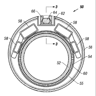
Figures 2 and 3 show embodiments of the present invention that may lx used in
a well.
The sand screen 50 generally comprises a base pipe 52 surrounded by a screen
54. To provide
for the flow of fluid into the base pipe 52, it has perforations therethrough.
The screen 54 is
typical to those used in wells such as those formed of a screen wrap or mesh
designed to control
the flow of sand therethrough. Surrounding at least a portion of the base pipe
52 and screen 54 is
a perforated shroud 56. The shroud 56 is attached to the base pipe 52 by, for
example, a
connecting ring or other connecting member extending therebetween and
connected by a known
method such as welding. The shroud 56 and the screen 54 define a space
therebetween 55.
In the embodiment shown in Figure 2, the sand screen 50 comprises a plurality
of shunt
tubes 58 (also known as alternate paths) positioned in the space 55 between
the screen 54 and the
shroud 56. The shunt tubes 58 are shown attached to the base pipe 52 by an
attachment ring 60.
The methods and devices of attaching the shunt tubes 58 to the base pipe 52
may be replaced by
any one of numerous equivalent alternatives, only some of which are disclosed
in the
specification. The shunt tubes 58 can be used to transport gravel laden slurry
during a gravel
8
CA 02360472 2001-10-30
Attorney Docket No.: 68.0224
pack operation, thus reducing the likelihood of gravel bridging and providing
improved gravel
coverage across the zone to be gravel packed. The shunt tubes 58 can also be
used to distribute
treating fluids more evenly throughout the producing zone, such as during an
acid stimulation
treatment.
The shroud 56 comprises at least one channel 62 therein. The channel 62 is an
indented
area in the shroud 56 that extends along its length linearly, helically, or in
other traversing paths.
The channel 62 in one alternative embodiment has a depth sufficient to
accommodate a control
line 64 therein and allow the control line 64 to not extend beyond the outer
diameter of the
shroud 56. Other alternative embodiments may allow a portion of the control
line 64 to extend
from the channel 62 and beyond the outer diameter of the shroud 56 without
damaging the
control line 64. In another alternative, the channel 62 includes an outer
cover (not shown) that
encloses at least a portion of the channel 62.
To protect the control line 64 and maintain it in the channel 62, the sand
screen 50 may
comprise one or more cable protectors, or restraining elements, or clips, 66.
The clips 66 attach
to the shroud in the channel 62 and are adapted to selectively receive and
hold a control line 64
therein. In the embodiment shown in Figure 2, the clip 66 has a dovetail
groove forming a mouth
with a smaller width than the inner portion of the clip 66. In this
embodiment, the control line 64
is noncircular and capable of fitting through the mouth in one orientation
after which it is
reoriented so that it cannot pass through the mouth. Thereby the control line
64 is held in the clip
66.
9
CA 02360472 2001-10-30
Attorney Docket No.: 68.0224
Figure 4 shows an alternative embodiment wherein the groove in the clip 66 is
rectangular rather than dovetail shaped. Note that the clip 66 may be formed
with resilient sides
to allow a control line 64 to be snapped into position. In the embodiments
shown, the clip 66 has
a length such that holds a significant length of the control line 64. The
clips 66 shown may be
replaced by any one of numerous equivalent alternatives, only some of which
are disclosed in the
specification. In general, any device or method capable of holding the control
line 64 in the
channel 62 may be used, and are herein referred to as restraining elements 66.
The restraining
element 66 can be a single unit having a length that is as long as the
longitudinal length of the
channel 62. Alternately, multiple restraining elements 66 of shorter length
can be utilized, such
as shown in Figure 3.
Figure S shows an alternative embodiment in which the channel 62, or control
line
passageway, is fully enclosed. This alternative embodiment is illustrative in
showing the channel
62 or control line passageway may take may forms from an open channel to a
fully encircled
channel. Further, although shown as a channel having square corners, the
channel may be
rounded or otherwise configured. Figure 5 also illustrates that the channel
may house a plurality
of control lines 64 therein.
Note that, as used herein, control line 64 includes fiber optic lines,
hydraulic lines,
electrical lines, other types of control lines used in wells, and combinations
thereof. The control
line 64 may be used to power or communicate with, collectively referred to as
telemetering, a
device placed in the well. The devices may include any device commonly
controlled by a control
line in a well, such as intelligent completion devices, valves, meters,
sensors, gauges, and other
devices.
CA 02360472 2005-O1-19
78543-51
Although only a few exemplary embodiments of this
invention have been described in detail above, those skilled
in the art will readily appreciate that many modifications
are possible in the exemplary embodiments without materially
departing from the novel teachings and advantages of this
invention. Accordingly, all such modifications are intended
to be included within the scope of this invention as defined
in the following claims.
11