Note: Descriptions are shown in the official language in which they were submitted.
CA 02367521 2007-07-03
1
1 PIPE CLEANING DEVICE
2
3 The present invention relates to a vehicle, and more
4 particularly, but not exclusively, to a vehicle for
travelling in pipelines, tubing strings and other
6 conduits.
7
8 Conventionally, non-destructive inspection,
9 intervention and cleaning apparatus is transported
through a pipeline or other conduit using a pipeline
11 device generally referred to as a pipeline pig or
12 crawler.
13
14 Pipeline pigs typically consist of a series of
deformable disks, typically of polyurethane, which are
16 securely mounted on a body or moulded as a one-piece
17 unit from polyurethane or polystyrene foam. These
18 disks or moulded forms typically form a seal with the
19 internal surfaces of the conduit, the pig being
typically driven in the direction of flow of fluids
21 within the pipeline due to differential pressure
22 created across the pig. Pigs move with the fluid flow
23 in the conduit.
24
Conventional pigs have the disadvantage in that the
26 velocity and direction of movement of the pig is
27 controlled by the differential pressure across the
28 device (ie the direction and rate of flow of fluids
29 within the pipeline). Thus, to control the velocity
and direction of movement of the pig requires control
31 over the flow of fluids within the pipeline. In
32 particular, fluid flowing through the conduit typically
33 have excursions of velocity and acceleration as the
34 fluid flow within the pipeline is often not a constant
due to various factors.
CA 02367521 2007-07-03
2
1 Many solutions have been attempted to overcome these
2 problems, for example by passive control of the pig
3 wherein a fixed bypass of drive fluids is used to
4 control the velocity and direction of the pig. Other
embodiments of conventional pigs incorporate a degree
6 of controllability by using flow-controlled or
7 pressure-controlled bypass devices. In an attempt to
8 overcome the reliance of pigs on the internal fluid
9 flow within the conduit for motive powers, external
power and control of these devices is used via, for
11 example, umbilical power cables or wire line power
12 cables attached from a surface vessel, or the like, to
13 the device itself.
14
However, these devices rely on an external power source
16 outwith the pipeline conduit and also on a power
17 transfer cable or hose, which typically limits the
18 range of travel of such devices.
19
According to an aspect of the present invention there
21 is provided a vehicle for a pipe, having a power
22 generator driven by fluid flowing past the generator,
23 and at least one drive means wherein the power from the
24 generator is used to power the drive means to move the
vehicle, and a power transmission mechanism connecting
26 the generator to the drive means, wherein the power
27 from the generator is transmitted from the generator
28 via the transmission mechanism to the drive means to
29 power the drive means and to propel the vehicle axially
along the pipe, wherein the drive means includes at
31 least one drive head biased radially outwards from the
32 vehicle to contact the inside surface of the pipe, and
33 wherein the at least one drive head is rotatable
34 relative to the vehicle around the axis of the vehicle
and wherein the attitude of the drive head with respect
36 to the axis of the pipe can be set at a selected value
CA 02367521 2007-07-03
3
1 between 0 and 90 , whereby rotation of the drive means
2 around the axis of the vehicle drives the head in a
3 helical path on the inner surface of the pipe, thereby
4 propelling the vehicle axially along the pipe.
6 According to another aspect of the present invention,
7 there is provided a method of propelling the vehicle of
8 the vehicle described in the preceding paragraph,
9 through a pipe, the method comprising the steps of
passing fluid past the vehicle to drive the generator,
11 transmitting power from the generator via the
12 transmission mechanism to rotate the drive head around
13 the axis of the vehicle, and setting the attitude of
14 the drive head with respect to the axis of the vehicle
at a selected value between 00 and 90 , whereby
16 rotation of the drive means drives the drive head in a
17 helical path on the inner surface of the pipe, thereby
18 propelling the vehicle axially along the pipe. A
19 magneto-hydro-dynamic generator can be used as the
generator, but it is preferred that a simple turbine,
21 vane or paddle is employed. The turbine can be mounted
22 to rotate axially in the pipe or across the axis, and
23 its rotation driven by the fluid flow is used to power
24 movement of the vehicle.
26 According to another aspect of the present invention,
27 there is provided a vehicle for a pipe, having a power
28 generator driven by fluid flowing past the generator
29 and at least one drive means wherein the power from the
generator is used to power the drive means to move the
31 vehicle, wherein the drive means can rotate around the
32 axis of movement of the vehicle.
33
34 According to another aspect of the present invention,
there is provided a vehicle for a pipe, having a power
36 generator driven by fluid flowing past the generator
CA 02367521 2007-07-03
4
1 and at least one drive means wherein the power from the
2 generator is used to power the drive means to move the
3 vehicle, wherein the drive means comprises first and
4 second drive arms adapted to rotate in opposite
directions.
6
7 According to another aspect of the present invention,
8 there is provided a vehicle for a pipe, having a power
9 generator driven by fluid flowing past the generator
and at least one drive means wherein the power from the
11 generator is used to power the drive means to move the
12 vehicle, wherein the drive means comprises a helical
13 arm.
14
The drive means can comprise wheels disposed against
16 the inner surface of the pipe and coupled to the
17 turbine vane via a gearbox and shaft so that rotation
18 of the turbine shaft drives the drive wheels along the
19 inside surface of the pipe.
21 The drive wheels can be arranged to grip or cut into
22 the inner surface of the pipe. This enhances the grip
23 that the vehicle exerts on the pipe and also allows the
24 vehicle to clean wax and scale etc from the inner
surface while it is travelling. In certain embodiments
26 that travel against the flow in the pipe, this is a
27 great advantage, because the scale, wax or other debris
28 dislodged from the inner surface of the pipe simply
29 flows downstream with the flow of fluid, and does not
travel ahead of the vehicle and obstruct its progress
31 through the pipe. Even in embodiments that travel with
32 the flow, the debris will be swept before the vehicle.
CA 02367521 2007-07-03
1 Wheels are preferred, but could be substituted by
2 tracks or jets etc. The blades can optionally be
3 circular wheels with sharp edges mounted on the axis to
4 rotate and cut or grip the surface of the pipe.
5
6 The vehicle may have a scoop for dislodging debris on
7 the pipe wall that is separate from the wheels.
8 The power transmission from the turbine to the drive
9 means is normally by way of direct coupling via a drive
shaft to a gearbox, but other embodiments can
11 indirectly use the power of the rotation of the turbine
12 vane to charge a battery which can be used to power the
13 drive means. A combination of direct transmission and
14 battery storage is also feasible, and is especially
useful should flow through the pipe stop while the
16 vehicle needs to move. The power coupling can be
17 electrical and can drive an electric motor that drives
18 the wheels. Hydraulic motors and power couplings can
19 also be used.
21 Any suitable gearbox can be used, but in some
22 embodiments shown herein an epicyclic M007 Ingersol
23 Rand air motor gearbox was used.
24
The drive wheels are preferably disposed in a row of 4
26 or more on heads carried on arms on the vehicle. The
27 attitude of the heads can optionally be adjustable so
28 as to change the direction of force applied by the
29 wheels. This is especially useful to control the speed
and direction of movement of the vehicle as follows.
31
32 The heads can be set at 90o attitude with respect to
33 the axis of the pipe. In that attitude, with the
34 wheels all rotating in the same direction, the arms
rotate around the axis of the vehicle inside the pipe
36 without axial translocation. On the other hand, the
CA 02367521 2007-07-03
6
1 heads can be set at 0o, in which case the vehicle will
2 be propelled axially through the pipe at high speed
3 with no rotational movement. When the heads are set at
4 an intermediate attitude between 0- and 90o they will
follow a helical path through the pipe. The axial
6 speed will increase as the attitude approaches 0o and
7 will decrease as the attitude approaches 90o.
8 Conversely the pitch and extent of rotation of the arms
9 will increase as the attitude approaches 90o and
decrease as it approaches 0o. Thus the pitch of the
11 helical path (and therefore the ease with which the
12 vehicle moves against a fluid flow), and the axial
13 speed of movement can be controlled by altering the
14 attitude of the heads.
16 The pitch of the helical path through the pipe is a
17 useful parameter to control, since variation in this
18 allows a gearing for movement of the vehicle through
19 the pipe. With a high pitch of tight coils, the
vehicle will move slowly but will be able to overcome
21 high forces retarding it. With a low pitch helix the
22 vehicle will have a relatively lower power, but will
23 move with greater speed.
24
Furthermore, the attitude of the heads also.controls
26 the direction of axial movement in the pipe, as the
27 heads can be turned through 90o (parallel to the pipe
28 axis) and can drive the vehicle in the opposite
29 direction. Thus certain embodiments of the vehicle of
the invention can move against the flow of fluid in the
31 pipe, can stop or slow down or can proceed axially at
32 high speed by altering the attitude of the heads. Such
33 alteration can be set before use or can be effected
34 during use.
CA 02367521 2007-07-03
7
1 The vehicle can be controlled by remote wire if desired
2 but onboard control by PC or other electronic circuits
3 is one preferred option.
4
Simpler embodiments of the invention can simply be set
6 to travel at a given speed or pitch of helix through a
7 pipe without any other control features.
8
9 Telemetry gathered by the vehicle can be transmitted
along the pipe by wire, ultrasonics or other
11 conventional methods, or through the pipe wall to ROVs
12 etc by ultrasonic means etc.
13
14 An optional controller can comprise an on-board or
remote electronic device or can alternatively (or
16 additionally) comprise a mechanical governor or
17 electromechanical control system.
18
19 In certain embodiments the whole vehicle can rotate in
a spiral path as described later, but the body of the
21 vehicle preferably remains static relative to the
22 rotational movement of the turbine and drive arms.
23 This gives better purchase by the arms and can be
24 achieved by means of stabilisers which bear against the
inside surface of the pipe and resist rotation of the
26 body. Alternatively, two sets of drive arms can be
27 provided which are capable of contra-rotation. Two or
28 more turbine vanes can also be provided, also capable
29 of contra-rotation if desired.
31 The turbine vane can typically be attached to a
32 conventional turbine having a hub and driving a shaft,
33 but certain embodiments can comprise an annular ring
34 turbine having vanes extending inwardly from an outer
annular ring and no hub, with annular arrangements of
36 gears and motors coupled to the ring to drive the drive
CA 02367521 2007-07-03
8
1 means. The turbine vane can be featherable. Typical
2 turbine vanes can comprise ROV propellers (we used a
3 Curvetech HT series ROV thruster for some embodiments).
4
A cowling can be provided to guide fluid flowing past
6 the vehicle onto the turbine vanes and to guide it out
7 of the vehicle in an efficient manner.
8
9 The or each drive arm may be in the form of a radially
extending arm coupled to a gearbox and having a
11 telescoped and/or spring section to force the wheel at
12 the radially outward end against a wide variety of pipe
13 diameters.
14
Alternatively, the drive arm can be in the form of a
16 helix with a pitch variable from the controller and
17 having drive wheels spaced therealong. The helical arm
18 can be varied in pitch so as to vary the axial velocity
19 of the vehicle's path along the pipe, and also can be
compressed radially to fit different diameters of pipe.
21
22 Spring means or compressibility of the drive arms (by
23 hydraulic, pneumatic or spring means) is beneficial
24 since it allows the vehicle to negotiate bends in the
pipe or irregularities in the surface (e.g. flange
26 connections). The vehicle may have an articulated
27 joint to facilitate turning of the vehicle around
28 bends. Steering control may be incorporated in the
29 articulation or in the shock absorber units. In
certain embodiments the air cylinders/rams of the shock
31 absorbers were arranged to guide the vehicle around
32 corners in the pipe.
33
34 Embodiments of the present invention shall now be
described, by way of example only, with reference to
36 the accompanying drawings in which:-
CA 02367521 2001-10-03
WO 00/63606 PCT/GB00/01360
9
1 Fig. 1 is a part cross-sectional side elevation
2 of a vehicle according to the present invention
3 installed in a pipeline;
4 Fig. 2 is a part cross-sectional end elevation
showing the vehicle of Fig. 1 installed in a
6 pipeline;
7 Fig. 3 is a side elevation of a drive mechanism
8 for use with the vehicle of Figs 1 and 2;
9 Fig.'4 is a end elevation of the drive mechanism
of Fig. 3;
11 Fig. 5 is a partly cross-sectional'side
12 elevation of a power generator for use with the
13 vehicle of the present invention;
14 Fig. 6 is an end elevation of the power
generator of Fig. 5;
16 Fig. 7 is a schematic side elevation of an
17 annularly mounted power generator;
18 Fig. 8 is an enlarged view of the power
19 generator of Fig. 7;
Fig. 9 is an enlarged side elevation of a
21 electric mechanical power generator;
22 Fig. 10 is a side elevation of an alternative
23 embodiment of a vehicle;
24 Fig. 11 is a side elevation of a third
embodiment of a vehicle;
26 Fig. 12 is a isometric view of the power
27 generator of Figs 7 to 9;
28 Fig. 13 is a side elevation of a power means for
29 use with the present invention;
Fig. 14 is a schematic side elevation of a
31 fourth embodiment of the present invention;
CA 02367521 2007-07-03
. ~ . 10
1 Fig. 15 is an isometric view of the vehicle of
2 the Fig. 14;
3 Fig. 16 is a side elevation of a fifth
4 embodiment of a vehicle;
Figs 17a to 17c illustrate a helix drive
6 assembly;
7 Fig. 18 shows an alternative wheel drive
8 assembly;
9 Figs 19a and 19b show a caterpillar or track drive
assembly;
11 Fig. 20 shows a trailer attached to a vehicle;
12 Fig. 21 is a sectional perspective view of a
13 sixth embodiment of a vehicle;
14 Fig. 22 is a side view of the vehicle of Fig.
21, showing a line drawing of the vehicle;
16 Fig. 23 is a side view of the vehicle of Fig.
17 21, showing an exterior view of the vehicle;
18 Fig. 24 is end view of the vehicle of Fig. 21;
19 Fig. 25 is a perspective view of the vehicle of
Fig. 21;
21 Fig. 26 is a side view of a seventh embodiment
22 of a vehicle;
23 Fig. 27 is perspective view of the vehicle of
24 Fig. 26;
Fig. 28 is a side view of an eighth embodiment
26 of a vehicle;
27 Fig. 29 is a shaded side view of the vehicle of
28 Fig. 28;
29 Fig. 30 is a perspective view of the vehicle of
Fig. 28;
CA 02367521 2001-10-03
WO 00/63606 PCT/GB00/01360
11
1 Fig. 31 is a second perspective view of the
2 vehicle of Fig. 28;
3 Fig. 32 is a sectional perspective view of the
4 vehicle of Fig. 28 in use; and,
Fig. 33 is a second sectional perspective view
6 of the vehicle of Fig. 28 in use.
7
8 Referring to the drawings, Figs. 1 and 2 show a first
9 embodiment of a vehicle, generally designated 10,
installed in a pipeline or conduit 12. Vehicle 10
11 includes a power generator, generally designated 14,
12 which typically comprises a propeller or turbine,
13 which has a plurality of turbine blades 16. As shown
14 in Fig. 2, vehicle 10 is provided with three radially
displaced turbine blades 16, although it will be
16 appreciated that any number of turbine blades may be
17 used. Blades 16 are attached to a central hub 18
18 which has an extension shaft 20 located in an axial
19 bore 18b of the hub 18, and may be retained in
position using any conventional means. The shaft 20
21 is rotatably mounted in a stator 24 using an annular
22 thrust bearing 26 to allow for rotational movement of
23 the shaft 20 within the stator 24. Shaft 20 is
24 coupled by any conventional means to an input shaft
28 of a gearbox 30, the input shaft 28 rotating on a
26 second annular thrust bearing 32. An output shaft 34
27 of the gearbox 30 is coupled by any conventional
28 means (e.g'. via a screw) to a drive mechanism,
29 generally designated 36.
CA 02367521 2001-10-03
WO 00/63606 PCT/GBOO/01360
12
1 As shown more clearly in Fig. 2, drive mechanism 36
2 includes three radially displaced drive arms 38.
3 Drive arms 38 each have a whepl housing 40 at a
4 distal end, the wheel housings 40 having at least one
wheel 42 rotatably mounted therein. Wheel housing 40
6 may be attached to drive arm 38 by any conventional
7 means, but is advantageously telescopic and spring
8 loaded using spring 44 which biases wheel housing 40
9 radially outwards, thus forcing wheels 42 into
contact with an inner surface 12i of the pipeline 12.
11
12 Spring 44 facilitates biasing of wheels 42 into
13 engagement with inner surface 12i of pipeline 12, and
14 advantageously provides two further functions.
Firstly, spring 44 allows for adjustment of the
16 radial displacement of the wheel housing 40, wherein
17 the vehicle 10 may be centred and used within
18 different pipelines of varying inside diameter.
19 Secondly, springs 44 also function as shock absorbers
to absorb any radial inward force which may be
21 applied to the drive arm by any inwardly projecting
22 object, such as a welds or flange joints on the
23 pipeline 12, which protrude inwardly from the inner
24 surface 12i. Thus, vehicle 12 may be used with
various pipelines having different inner diameters,
26 and vehicle 10 may also negotiate with minimal
27 reduction in speed any inwardly protruding objects
28 within the'pipeline 12.
29
Each drive arm on the embodiment shown in Fig. 2 has
31 five wheels 42 disposed on a semicircular axis 46.
CA 02367521 2001-10-03
WO 00/63606 PCT/GBOO/01360
13
1 This arrangement ensures that at least one wheel 42
2 contacts the inner surface 12i of the pipeline 12
3 during use, and also facilitates use of the vehicle
4 10 with pipelines having inner surfaces which are not
precisely circular in cross-section.
6
7 Vehicle 10 is also provided with at least one
8 stabiliser, generally designated 48. As shown more
9 clearly in Fig. 2, vehicle 10 has three radially
displaced stabilisers 48 although it will be
11 appreciated that any number of stabilisers 48 may be
12 used. Stabiliser 48 typically includes a wheel
13 housing 50 which has a wheel 52 biased by a spring 54
14 into engagement with the inner surface 12i of the
pipeline 12. It will be appreciated that spring 54
16 provides the same functions as spring 44 in the drive
17 mechanism 36. Stabiliser 48 may be attached to
18 vehicle 10 using any conventional means.
19
Referring to Fig. 4, the drive arm 38 includes a
21 spline bush 56 which is provided with a longitudinal
22 slot 58, a spline 60 which is attached to a central
23 hub 62 and project outwardly. Spline 60 is provided
24 with a pin 64 which is retained within the slot 58 of
the spline bush 56. When the vehicle 10 is being
26 inserted into a pipe 12, the radial displacement of
27 the wheels 42 is reduced by moving the wheel housing
28 40 radially inward and locking in place using the pin
29 64, as shown by arm 38a in Fig. 4. Once the vehicle
10 is within the pipeline 12, the pin 64 is released
31 by any conventional means so that the drive arm 38
CA 02367521 2001-10-03
WO 00/63606 PCT/GBOO/01360
14
1 extends radially outward whereby wheels 42 contact
2 the inner surface 12i of the pipeline 12.
3
4 The wheels of the drive mechanism 36 shown in Figs 1
to 4 are illustrated as being angled perpendicular to
6 the longitudinal axis of the pipeline 12. However,
7 the angular displacement or attitude of the wheel
8 housings 40 can be optionally adjusted using an
9 adjustment mechanism (not shown) which allows the
angular displacement of the wheel housings 40 to be
11 rotated relative to the longitudinal axis of the
12 pipeline 12. This rotation of the wheel housing 40
13 allows the direction of travel and/or the velocity of
14 the vehicle 10 within the pipeline 12 to be adjusted.
16 The wheel housing 40 can be rotated relative to the
17 longitudinal axis of the pipeline 12 so that it is in
18 a plane which is between 90 (i.e. perpendicular to)
19 and 0 (i.e. parallel with) the longitudinal axis of
the pipeline 12. Thus, as the wheels move between
21 the 90 position towards the 0 position, the
22 velocity and the helical pitch of the path travelled
23 by the vehicle 10 can be controlled. The closer the
24 plane of the wheels is to the 0 position parallel
with the longitudinal axis of the pipeline 12, the
26 faster the velocity of the vehicle 10 in the
27 direction of travel will be and the path of the drive
28 arms will follow a more relaxed pitch of helix.
29
By changing the angular displacement of the wheel
31 housing 40, the direction of travel of the vehicle 10
CA 02367521 2001-10-03
WO 00/63606 PCT/GBOO/01360
1 can also be controlled. When the plane is
2 perpendicular to the longitudinal axis, the drive
3 mechanism will not exert any axial force on the
4 vehicle. With the drive heads set at 90 , the
5 vehicle will travel with the flow in the pipeline.
6 This can be a useful feature in retrieving the
7 vehicle, since a signal can be given to the drive
8 heads to adopt the 90 position (or that can be their
9 default position in the event of failure) and the
10 vehicle can then be recovered at the end of the
11 pipeline after moving with the flow.
12
13 Referring to Fig. 1, if the front of the wheel
14 housing 40 (defined by the direction of rotation of
15 the wheels) is rotated towards the left as shown in
16 Fig. 1, the vehicle will move towards the left;
17 conversely, if the drive arm 38 is rotated so that
18 the front of the wheel housing 40 moves towards the
19 right as shown in Fig. 1 the vehicle will move in the
reverse direction (that is towards the right of Fig.
21 1). Thus, vehicle 10 is bi-directional, the
22 direction of travel being set by the angular
23 displacement of the wheels 42. In this way, the
24 velocity and the direction of travel of the vehicle
10 is independent of the rate and direction of fluid
26 flow within the pipeline 12, and independent of the
27 direction and speed of travel of the wheels. Thus,
28 the vehicle 10 can either go against or with the flow
29 of fluid in the pipeline 12.
CA 02367521 2001-10-03
WO 00/63606 PCT/GB00/01360
16
1 It will be appreciated that with the heads set in an
2 intermediate position the arms move in a spiral or
3 helical path (at a pitch depepdent on the attitude of
4 the heads) thereby moving the vehicle in either a
forward or a reverse direction through the pipeline
6 12. This is advantageous as it reduces the power and
7 torque required to overcome forces retarding the
8 vehicle 10, such as fluid flow.
9
It should be noted that the velocity and direction of
11 the vehicle 10 may also be changed by adjusting the
12 gearbox ratios and/or by providing a reverse gear
13 within the gearbox 30.
14
In use, the vehicle 10 is inserted into the pipeline
16 12 by radially displacing the wheel housings 40
17 inward as described above (i.e. to the position of
18 arm 38a in Fig. 4), and then releasing the wheel
19 housings 40 once the vehicle 10 is in the pipeline 12
so that the wheels 42 contact the inner surface 12i
21 of the pipeline 12. The attitude of the wheel
22 housings 40 is then adjusted to give the required
23 direction of travel of the vehicle 10 and also to set
24 the pitch of helix (and therefore the axial velocity)
in the direction of travel.
26
27 The pipeline 12 typically contains a fluid, such as
28 gas or oth~r hydrocarbon or water etc, which is '
29 travelling in the direction shown by arrows 66 in
Fig. 1. The fluid impacts on the blades 16 of the
31 power generator 14 and causes their rotation.
CA 02367521 2001-10-03
WO 00/63606 PCT/GBOO/01360
17
1 Rotation of the blades 16 causes the shaft 20 to
2 rotate on thrust bearing 26 and thus the gearbox
3 input shaft 28 to rotate on bparing 32. The
4 rotational movement of the propeller blade 16 is thus
transmitted via the gearbox 30 (with a specific
6 gearing ratio if required) to the gearbox output
7 shaft 34. The rotational drive of the gearbox output
8 shaft 34 powers rotation of the wheels 42 which
9 causes the vehicle 10 to move in the specified
direction of travel at the specified velocity. In
11 this way, the vehicle 10 is capable of generating its
12 own power to drive the drive mechanism 36 by using
13 the inertia of the fluid impacting on the blade 16 to
14 cause a rotational torque which is transferred from a
high revolution and low torque, to a low revolution
16 and high torque applied to the wheels 42 via the
17 gearbox 30.
18
19 As the vehicle 10 moves in its intended direction of
travel, the drive arms spiral because of the attitude
21 of the wheel housing 40. This gives a mechanical
22 advantage in that the torque required to go against
23 the flow in the pipeline is comparatively less than
24 if the arms did not spiral. In certain embodiments,
the whole vehicle can spiral.
26
27 It should be noted that the structure of the drive
28 arms 378 arid the stabilisers 48 is advantageously
29 designed to reduce friction with the fluid flow, and
may be shaped similar to the turbine blades 16.
CA 02367521 2001-10-03
WO 00/63606 PCT/GBOO/01360
18
1 Thus, the drive arms 38 and stabilisers 48 can also
2 assist in propelling the vehicle 10.
3
4 The turbine can be located at one end (e.g. the back
end) of the vehicle, but can function equally well in
6 the centre of the vehicle. The vehicle can have one
7 drive mechanism or several in series, and more than
8 one vehicle can be used to drive a train of
9 instruments or cleaning devices etc. An optional
power supply can be provided on board or on a
11 separate vehicle or module.
12
13 Referring now to Figs. 5 and 6, there is shown an
14 alternative stabiliser 70. Stabiliser 70 is
pivotally attached to a bracket 72 on the stator 24
16 using any conventional means, such as a pin. The
17 stabiliser 70 includes a telescopic arm 74 which
18 extends radially outwards and is provided with a
19 wheel 76 at the distal end of it's outer cylinder
which contacts the inner surface 12i of the pipeline
21 12. A reaction arm 78 is attached to the outer
22 cylinder of the arm 74 of the stabiliser 70 and
23 extends perpendicular to the longitudinal axis of the
24 stabiliser arm 70. The reaction arm 78 is attached
to the stator 24 using a pin 80 which may be attached
26 to the stator 24 using a screw thread, for example,
27 which retains the reaction arm captive on the stator
28 but allow5 it to approach the stator body. A spring
29 82 is provided between the stator 24 and the
underside of the reaction arm 78, spring 82 providing
CA 02367521 2001-10-03
WO 00/63606 PCT/GBOO/01360
19
1 the same function as springs 44 and 54 described
2 above.
3
4 Thus, the stabiliser 70 can be adjusted so that the
vehicle 10 can be inserted into pipelines of varying
6 diameter and can also absorb shocks from protrusions
7 within the pipeline 12, absorbing the force imparted
8 by these intrusions using spring 82.
9
Referring now to Fig. 7, there is shown an
11 alternative embodiment of a power generator,
12 generally designated 90, which includes a plurality
13 of propeller blades 92, more clearly shown in the
14 perspective view of Fig. 12. The blades 92 are
mounted on an annular ring 94 which forms the rotor
16 of the power generator 90, and typically extend
17 radially inward. Annular ring 94 is mounted on a
18 plurality of bearings 96 on which the annular ring
19 rotates when fluid acts on the blades 92. The torque
generated by the blades 92 and annular ring 94 is
21 transferred through a gearbox, schematically shown at
22 98, which is housed in the annular housing or stator
23 of the vehicle 100, to a helical drive arm 102, which
24 will be described in detail hereinafter.
26 The vehicle 100 is provided with a plurality of
27 stabilising wheels 104 which are attached to frame
28 106 or a cowling of the vehicle 100. Frame 106
29 includes a flow focusing nozzle 108 which directs
fluid flow within the pipeline (not shown) towards
31 the blades 92 of the power generator 90.
CA 02367521 2001-10-03
WO 00/63606 PCT/GBOO/01360
1
2 The pitch of the blades 92 can be variable to effect
3 changes in the rotational velocity, thus changing the
4 velocity of the vehicle 100. Changing the pitch of
5 the blades 92 can also change the direction of travel
6 of the vehicle 100 from forward to reverse, using a
7 similar principle to the angular adjustment of the
8 wheel housing 40 in the vehicle 10 shown in Figs. 1
9 to 4. More than one blade can be provided e.g. from
10 2 - 10 blades may be suitable.
11
12 As illustrated in Fig. 13, the angular displacement
13 of the blades 16 of the vehicle 10 can also be
14 adjusted to effect changes in rotational velocity as
15 described above. This adjustment can govern the
16 velocity and direction of movement of the vehicle 10,
17 and can also make the vehicle 10 more efficient.
18 There may be more than one stage of propellers.
19
20 It should be noted that the power generator could
21 comprise an electro-mechanical power generator, as
22 opposed to a pure mechanical form. Referring to Fig.
23 9, there is shown an alternative power generator 110
24 which is similar to generator 90, but is of the
electro-mechanical type. In the embodiment shown in
26 Fig. 9, the power generator 110 includes blades 112
27 radially mounted on an annular ring 114. Annular
28 ring 114 has a wire coiled within the ring 114 which
29 acts as a rotor coil 116. The annular ring 114
rotates on bearings 118 provided on the stator 120,
31 the stator 120 including a stator coil 122 which
CA 02367521 2001-10-03
WO 00/63606 PCT/GBOO/01360
21
1 together with the rotor coil 116 comprises an
2 electrical generator. The power generated by the
3 electrical generator can be used to drive an
4 electrical motor (not shown) which can be used to
drive the driving mechanism which may comprise a
6 helix 124 or the driving mechanism 36 of vehicle 10.
7 In addition, the power from the electrical generator
8 can be used to power other equipment, such as
9 intervention equipment, inspection equipment,
cameras, gauges or cleaning equipment as will be
11 described hereinafter.
12
13 In addition, the electrical power generated by the
14 generator can be stored in, for example, a plurality
of batteries (not shown). This is advantageous where
16 if the fluid flow within the pipeline stops, the
17 power stored within the batteries may be used to
18 drive the electrical motor of the vehicle and hence
19 propel it along the pipeline, or any of the ancillary
equipment associated with the vehicle.
21
22 The drive arms can be set at a preselected angle to
23 govern direction (forward and reverse) and velocity
24 (by varying the pitch). Couplings may be mechanical
or viscous to allow synchronicity with multiple drive
26 wheels.
27
28 Fig. 16 shows an embodiment of a vehicle 200 which-is
29 an electrical equivalent of vehicle 10 shown in Figs
1 to 4. Vehicle 200 includes an electrical power
31 generator 202 which includes a turbine or propeller
CA 02367521 2008-01-15
22
1 204. Rotation of the propeller 204 generates
2 electricity (generally direct current (dc)) which
3 drives an electric motor 206 through a gearbox 208.
4 The electric motor 206 typically drives the drive
arms or other drive mechanism described herein. It
6 should be noted that vehicle 200 may require to be
7 intrinsically safe if used in a pipeline carrying
8 hydrocarbons to prevent accidental explosions.
9
Referring now to Fig. 10, there is shown a third
11 embodiment of a vehicle 130. The vehicle 130 is
12 similar to vehicle 10, except that two power
13 generating turbines 132, 134 are provided. This
14 duplication of turbines provides a more efficient
generation of power than a single turbine alone. It
16 will be appreciated that any number of turbines 132,
17 134 may be coupled together to increase the
18 efficiency further. The turbines 132 134 can be
19 arranged to contra-rotate if desired in order to
reduce stresses on the body of the vehicle 130, and
21 to increase efficiency.
22
23 The coupling from the gearbox to the drive mechanism
24 can be either a direct coupling or through a viscous
coupling to allow synchronisation with the other
26 drive wheels.
27
28 Vehicle 130 includes a convergent/divergent nozzle
29 136 which focuses the flow of fluid onto the turbines
132, 134 and then allows the fluid to expand
31 thereafter. Nozzle 136 has a plurality of wheels238
CA 02367521 2008-01-15
23
1 attached thereto, the wheels 138 providing a
2 stabilising function for the vehicle 130. Nozzle 136
3 may be attached to the main body of the vehicle 130
4 by any conventional means.
6 Referring to Fig. 11 there is shown a fourth
7 embodiment of a vehicle 140 which has two contra-
8 rotating drive mechanisms 142, 144 which are attached
9 through respective gearboxes 146, 148 to a central
power generator 150. Power generator 150 may be
11 either a mechanical or a electro-mechanical power
12 generator as described above. Gearboxes 146, 148 are
13 preferably matched gearboxes which contra-rotate the
14 drive mechanisms 142, 144. Provision of two contra-
rotating drive mechanisms 142, 144 provides for
16 balance of the vehicle 140 and also gives increased
17 power. The tendency of the vehicle body to rotate
18 can also be controlled by contra-rotating turbines.
19 A convergent/divergent nozzle 152 directs the fluid
flow within the pipeline towards blades 16 of the
21 power generator 150 as before, the nozzle 152 being
22 provided with wheels 154 to give a stabilising
23 function. It should be noted that the power
24 generator may comprise more than one turbine, as
shown in Fig. 10. The contra-rotating drives can be
26 helical as described in the previous embodiment.
27
28 Referring to Figs. 14 and 15, there is shown a
29 further alternative embodiment of a vehicle 160.
Vehicle 160 includes a helical drive arm 162 which is
31 provided on its outer surface with wheels 164, the
CA 02367521 2001-10-03
WO 00/63606 PCT/GBOO/01360
24
1 wheels 164 engaging the inner surface of a pipeline
2 (not shown). The arm 162 is attached at each end to
3 an annular collar 166 which allow for rotation of the
4 arm 162. The embodiment shown in Fig. 15 has a strip
contact on the helix 162 as opposed to wheels 164.
6 The helix can be extended and contracted in pitch by
7 means of a piston (not shown) between the two ends of
8 the device.
9
A power generator is encased within housing 168 and
11 may comprise any of the power generators described
12 herein. The housing 168 includes a mechanical
13 gearbox or the electro-mechanical power generator as
14 described previously. Spokes (not shown) connect the
power generator to the helical arm 162. A second
16 housing 170 provides for fluid flow out of the
17 vehicle 160. A plurality of stabilisers 172 are
18 provided on the outside of housings 168, 170,
19 preferably spaced equi-distantly around the
periphery. Stabilisers 172 typically incorporate
21 shock absorption as described before. It should be
22 noted that the mechanical shock absorption described
23 previously is by way of example only, and pneumatic,
24 hydraulic or other types of shock absorption coupling
may be used. The stabilisers resist rotation of the
26 housing 168, 170 by contact with the inner surface of
27 the pipe (not shown).
28
29 The interior surface of housing 168 may be
funnel-shaped to direct fluid flow through the
31 vehicle into the path of the power generator housed
CA 02367521 2001-10-03
WO 00/63606 PCT/GBOO/01360
1 therein. The power generator and the housing can
2 incorporate the gearbox or electrical power generator
3 such as a brushless DC motor. A shock absorber can
4 be incorporated if desired.
5
6 Referring to Figs. 21 to 25 there is shown a further
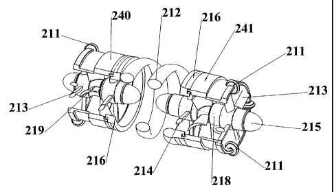
7 alternative embodiment of a vehicle 210. The vehicle
8 210 comprises a helical drive arm 212 attached at
9 each end to annular collars 216 which allow for axial
10 rotation of the arm 212. The rotation of the arm 212
11 against the wall of the pipe drives the'vehicle 210
12 in an axial direction along the pipe. This can be
13 against or in the direction of flow in the pipe. The
14 helix can be axially extended and contracted to alter
15 its pitch by means of a piston (not shown) between
16 the two ends of the device, in order to adjust the
17 speed of the vehicle 210. The simple driven rotation
18 of the helical arm 212 against the pipewall is
19 sufficient to power the translocation of the vehicle
20 210, but in certain embodiments wheels (not shown)
21 can alternatively or additionally be mounted on the
22 arm 212 (optionally driven by worm gears) in order to
23 drive the rotation.
24
25 Two power generators 218, 219 are provided. The
26 first typically powers the axial rotation of the
27 helical arm 212 as described herein after. The
28 second is typically reserved to power a trailer 300
29 which may comprise cleaning or inspection equipment
also described later. The vehicle 210 includes a
31 mechanical gearbox or the electro-mechanical power
CA 02367521 2001-10-03
WO 00/63606 PCT/GBOO/01360
26
1 generator as described for previous embodiments.
2 Spokes 214 connect the helix arm 212 to the power
3 generator. A plurality of optional stabilisers or
4 spokes 213 are provided on the outside of the vehicle
210. The stabilisers 213 and arms 214 typically
6 incorporate any type of shock absorption as described
7 before. Optionally wheels 211 are provided on the
8 vehicle 210 to contact the inner surface of the pipe
9 (not shown) preferably spaced equi-distantly around
the periphery to resist rotation of the housing 240,
11 241 and a nose cone 215 which directs fluid flow
12 within the pipeline towards the blades of the
13 generator.
14
Other features of previous embodiments particularly
16 from vehicle 160, may be incorporated into this
17 embodiment.
18
19 Referring now to Figs. 26 to 27 there is shown a
further alternative of a vehicle 220. A helical arm
21 222 is provided connected to annular rings (not
22 shown) on the housing 224, 225. The power generator
23 is housed within the helical arm 222 and may comprise
24 any of the power generators described herein. The
vehicle 220 includes a mechanical gearbox or the
26 electro-mechanical power generator as described
27 previously. Arms 226, 227 extend from the main axle
28 to the helix arm 222 and so link the power generator
29 to the helix 222. Typically a piston (not shown) is
provided to extend and contract the two ends of the
31 helical arm 222. Stabilisers 221 resist rotation of
CA 02367521 2001-10-03
WO 00/63606 PCT/GBOO/01360
27
1 the outer bearing housing 228, 229. An advantage of
2 this embodiment is that additional apparatus(not
3 shown) e.g. cleaning or surveying equipment, may be
4 mounted within the housing 228, 229 or provided for
in a tractor 300 described herein later, conveniently
6 attached to the vehicle 220.
7
8 Referring now to Figs. 28 to 31 there is shown a
9 further alternative embodiment of a vehicle 230. The
vehicle 230 comprises two helical arms 231, 232 each
11 attached to an annular ring 233, 234 respectively.
12 Spokes (not shown) connect a power generator 235 to
13 the helical arms 231, 232. The annular rings 233,
14 234 are powered to rotate oppositely with respect to
each other by the power generator 235 which may
16 comprise any of the power generators described herein
17 and a mechanical gearbox or the electro-mechanical
18 power generator as described previously. The contra-
19 rotating helical arms 231, 232 provide extra
stability to the vehicle. A piston (not shown) may
21 be provided to extend or contract the length of each
22 helical arm 231, 232. Referring to Figs. 32 to 33 the
23 vehicle 230 is shown in use, moving through a pipe
24 236.
26 Referring now to Figs. 17a to 17c, the pitch of the
27 helical arm and thus the axial velocity of the
28 vehicles 160 may be controlled. Helical arm 162
29 typically comprises an annular ring which has a slit
174 therein. As shown in Fig. 17a, if the arm 162 is
31 held in an annular ring, no axial force will be
CA 02367521 2001-10-03
WO 00/63606 PCT/GBOO/01360
28
1 imparted to the vehicle and it will remain idle,
2 although the arm 162 can rotate. However, if one end
3 of the arm 162 is held stationary as shown in
4 Fig. 17b and the other end is displaced towards the
left, the arm 162 will adopt a helical configuration
6 and the vehicle will move towards the left.
7 Referring now to Fig. 17c, if the same end of the arm
8 162 is held stationary and the other end is moved
9 towards the right as shown in Fig. 17c, then the
vehicle will move towards the right. It should be
11 noted that it is the direction of initial
12 displacement of the arm 162 which governs the
13 direction of travel of the vehicle, thus making the
14 vehicle bi-directional irrespective of the direction
of rotation of the arm 162. In addition, by varying
16 the pitch of the helix to a greater or lesser extent,
17 the velocity of the vehicle in the direction of
18 travel can be increased or decreased accordingly.
19 For example, forcing the arm 162 into a loose helix
increases the speed, and conversely forcing the arm
21 162 into a tighter helix decreases the speed but
22 lowers the gearing of the vehicle so that it can
23 travel more easily against retarding forces. The
24 axial velocity of vehicles 210, 220, 230 may be
varied by altering their helical arms 162, 212, 222,
26 231, 232 in a similar manner. In addition to
27 providing a drive means, the helical arms 162, 212,
28 222, 231, 232 remove matter from the inside of the
29 pipe through which the vehicle 160, 210, 220, 230
travels.
31
CA 02367521 2001-10-03
WO 00/63606 PCT/GB00/01360
29
1 Moreover, when the vehicle 160, 210, 220, 230
2 approaches a bend in the pipe through which it is
3 travelling, the helical arm can automatically adapt
4 to the shape of the bend and so reduce stresses
applied to the vehicle.
6
7 For embodiments comprising a helical arm, the pitch
8 of the helix can be varied by increasing or
9 decreasing the distance between the annular collars,
which can be done by means of a hydraulic ram or
11 similar device. This can be triggered remotely or as
12 a result of the on-board controller.
13
14 A further alternative drive mechanism for the vehicle
is shown in Fig. 19a. An endless track unit 180 is
16 provided on the end of the drive arm 38 to provide
17 the drive force to the vehicle. The endless track
18 unit typically comprises a plurality of wheels 182
19 upon which an endless driven belt 184 can rotate. A
worm gearing, illustrated in Fig. 19b, translates the
21 rotation from the output shaft 34 of the gearbox 30
22 to a motion that drives the belt 184.
23
24 It should be noted that the attitude of the track
unit 180 can be adjusted using an adjustment
26 mechanism similar to that for the wheel housing 40
27 shown in Figs 1 to 4. This allows for control of the
28 speed and direction of the vehicle to which the
29 tractor unit 180 is attached as previously described.
The worm gearing shown in Fig. 19b includes a shaft
31 186 which has a spiral protrusion 188 thereon. A
CA 02367521 2001-10-03
WO 00/63606 PCT/GBOO/01360
1 second shaft 190 is mounted perpendicular to the
2 first shaft 186, the second shaft 190 being provided
3 with a spiral protrusion 192 similar to protrusion
4 188 for engagement therewith. Thus, rotation of the
5 first shaft 186 causes inter-engagement of the
6 protrusions 188, 192 which then rotates shaft 190.
7
8 Referring now to Fig. 20, there is shown a vehicle
9 which may comprise any of the vehicles 10, 130, 140,
10 160, 200, 210, 220, 230 which has a trailer 300
11 attached thereto. The trailer 300 is attached to the
12 tractor unit 10 using a coupling 202, the coupling
13 202 preferably including electrical connectors for
14 transferring the electrical power generated by the
15 vehicle 10 to the trailer 300. It should be noted
16 that the trailer 300 can be attached to the tractor
17 10 so that the trailer is either pushed or pulled
18 along. The trailer 300 typically includes pipeline
19 logging, inspection and/or cleaning equipment. The
20 coupling 202 is preferably articulated so that the
21 tractor 10 and trailer 200 can negotiate any bends in
22 the pipeline. The tractor 10 can be used to pull or
23 push any kind of downhole equipment which may be
24 required such as pipeline intervention, cleaning or
25 inspection equipment, as will be appreciated by those
26 skilled in the art. It should also be noted that the
27 pipeline intervention, cleaning or inspection
28 equipment can be attached to the vehicle, thus
29 negating having to use a trailer 300.
CA 02367521 2001-10-03
WO 00/63606 PCT/GBOO/01360
31
1 The cleaning equipment is typically used to clean the
2 interior of the pipeline. This increases the
3 efficiency of fluid transportthrough the pipeline.
4
Surveying and inspection equipment can be used to
6 assess the integrity and serviceability of the
7 pipeline.
8
9 The vehicles 10, 130, 140, 160, 200, 210, 220, 230
may be used in any application which requires
11 cleaning, inspection or other work performed within a
12 pipe, some (not exclusive) examples are within the
13 water, gas, nuclear or oil industries. The vehicle
14 is capable of travelling in pipes used to transport
liquid, gas or a mixture thereof.
16
17 The vehicle may be launched into production tubing
18 from a platform or a remote wellhead or well cluster
19 while production is in progress. Thus, inspection
and/or cleaning can be achieved without affecting the
21 production of hydrocarbons.
22
23 The vehicle may carry an odometer which can trigger
24 the release of a fail-safe mechanism so that the
vehicle may be retrieved after a certain distance.
26 The fail-safe mechanism may also be triggered
27 externally by a signal transmitted though the pipe
28 wall or a probe therein.
29
The vehicle may be left idling within a pipeline
31 until an external signal triggers the vehicle to move
CA 02367521 2001-10-03
WO 00/63606 PCT/GB00/01360
32
1 in a given direction at a given velocity to inspect
2 or clean the pipeline or the like. As the direction
3 and speed of the vehicle is controllable, the vehicle
4 can be used to do an initial high speed scan of the
entire pipeline, noting areas which require further
6 and more detailed inspection or cleaning. The
7 vehicle can then be directed back to these areas by
8 reversing its direction and then the velocity of the
9 vehicle can be reduced to give a more thorough
inspection.
11
12 The vehicle is advantageously provided with an
13 electronic control module, which may comprise an on-
14 board computer for example, to control the speed and
direction of the vehicle. In addition, the control
16 module can provide other functions such as the
17 telemetry system and/or control and operation of the
18 cleaning, inspection or intervention equipment
19 attached thereto.
21 Any of the vehicles described herein may be provided
22 with a fail-safe mechanism to ensure that the vehicle
23 can be retrieved in the event of a failure. The
24 fail-safe mechanism may be, for example, a parachute
or drogue which is deployed from the rear of the
26 vehicle. The parachute/drogue will open once
27 deployed and will catch the flow of fluid within the
28 pipeline, thus carrying the vehicle with the flow Qf
29 fluid to any point within the pipeline where it can
be retrieved. A line may optionally be attached to
CA 02367521 2001-10-03
WO 00/63606 PCT/GB00/01360
33
1 the vehicle so it may be towed in the event of a
2 failure.
3
4 The vehicle can also carry a telemetry system wherein
the instrumentation or other equipment carried
6 thereon can communicate with a receiver located
7 either at the surface or on an ROV which is moving
8 alongside the vehicle, but perhaps outwith the
9 pipeline. The telemetry system can communicate using
any conventional means such as the pipeline,
11 ultrasonic sound or otherwise.
12
13 In certain embodiments the drive wheels/arms can be
14 set at an angle for a particular velocity that can be
adjusted by the control module. In the case of
16 electrical drive means, the angle and speed of
17 rotation may change in order to adjust the vehicle's
18 axial velocity through the pipe. In the case of
19 mechanical couplings, the velocity may be varied
according to the angle of contact between the
21 wheel/arm and the pipe wall, or by changing the
22 gearbox ratios. The gearbox can be adapted to reduce
23 rpm and increase torque.
24
Modifications and improvements may be used to the
26 foregoing without departing from the scope of the
27 present invention. Air or hydraulic rams may be
28 provided on the vehicle and an articulated joint made
29 so that the vehicle can negotiate bends within the
pipeline.
31
CA 02367521 2001-10-03
WO 00/63606 PCT/GBOO/01360
34
1 One advantage that arises from the helical form of
2 drive arm is that a vehicle with such an arm can be
3 moved from narrow diameter pipes to large diameter
4 pipes and the helix can radially expand to a large
extent to force the arm against the wall of the pipe
6 in each case.