Note: Descriptions are shown in the official language in which they were submitted.
CA 02375577 2002-03-07
s OPTOELECTRONIC DOCUMENT READER FOR READING UV I IR VISIBLE INDICIA
Field of the Invention
This invention relates generally to the field of security equipment and, more
particularly, to an optoelectronic document reader for reading matter which is
visible only
1 o in the presence of illumination outside of the visible light spectrum i.e.
ultraviolet (UV) or
infrared (1R) light, such matter being in the form of text, images or other
indicia printed onto
a document or surface-visible matter embedded within a substrate of a
document.
Background of the Invention
15 Some known methods for improving the security of a document, such as a
passport
or other identity document, utilize materials which are visible only in the
presence of
ultraviolet (UV) light. Such materials have been added to certain inks used
for security
printing to print UV-visible indicia onto a document, whereby the average
person viewing
such document would be unaware that such indicia is present on the document
but a
2 o knowledgeable person (e.g. a customs officer) would inspect such document
under UV
illumination to identify such indicia for purposes of assessing the
authenticity of the
document. The known devices used in the identification of such covert UV
printed indicia
comprise UV fluorescent tubes which emit UV illumination. In use, a document
to be
inspected is placed under the UV illumination emitted by such a device so that
any covert
2 s UV-visible indicia on the document is caused to fluoresce with a visible
light (i.e. is made
visible to an inspector's eye). Disadvantageously, however, such devices are
passive only,
in that they simply serve to illuminate a specific area; they are themselves
unable to read
CA 02375577 2002-03-07
(i.e. via an automated process so as to interpret) invisible indicia which has
been printed
by means of a UV fluorescent ink. Instead, a user of such known devices is
required to
manually view and personally interpret the resulting image in order to
determine whether
the document comprises any covert indicia. Moreover, UV fluorescent tubes have
a
lengthy stabilization time and, therefore, they are unable to accommodate any
high speed
1 o processing application such as would be required by an automated device
for reading UV-
ink printed indicia. Moreover, such tubes are inherently unstable (and, thus,
unreliable)
because the peak wavelength of the illumination they produce typically varies
over time.
There is a need, therefore, for a document reader which operates on an
automated
basis for relatively high speed processing of security documents having matter
associated
therewith which is visible only when illuminated by UV or IR light. Further,
there is a need
for a document reader which is able to read such covert UV-ink (or IR-ink)
printed indicia
on a full-page basis. There is also a need for such a reader which is able to
illuminate one
or more predetermined surface areas of a document with light whose frequency
or
2o frequency band is/are within one of the infrared, visible and ultraviolet
light frequency
bands, depending on the particular indicia on such areas of the document which
is to be
read, and to switch rapidly from one such frequency or band to another. Still
further, there
is a need for a document reader which is able to automatically read and
interpret such
indicia. Moreover, there is a need for such a document reader comprised of
solid state
components enabling a reduction or elimination of moving parts.
- 2 -
CA 02375577 2002-03-07
Summary of the Invention
In accordance with the invention there is provided an optoelectronic document
reader and method for automated reading of first indicia in a machine readable
zone of a
document, the first indicia being invisible when illuminated with visible
light and visible
1 o when illuminated with invisible light of a predetermined frequency range.
A reading surface
is provided for placement of a document comprising the machine readable zone
to be read
by the reader. A plurality of first light sources are spaced apart from the
reading surface
and configured for illuminating the machine readable zone of a document on the
reading
surface with invisible Light of the predetermined frequency range (e.g. UV
fight having a
peak wavelength of 370nm) when the first light sources are activated so as to
cause the
first indicia to become visible. An image sensor is configured for capturing
an image
defined by light focussed thereon and producing electronic data representative
of the
captured image. An optical path extends between the reading surface and the
image
sensor and comprises a lens configured for focussing light defining an image
onto the
2 o sensor. A document image comprising the first indicia defined by light
emitted and/or
reflected by the machine readable zone of the document on the reading surface
when the
first light sources are activated, is transported to the sensor via the
optical path and
captured by the sensor. A document controller is configured for identifying
the indicia from
the captured image and outputting the identified indicia for display andlor
processing;
- 3 -
CA 02375577 2002-03-07
The first light sources may be UV LED's configured for emitting light of a
predetermined ultraviolet frequency range whereby the first indicia comprises
UV
fluorescent matter configured for emitting visible light when illuminated by
the light of the
predetermined ultraviolet frequency range. Preferably, the optical path is
folded by a
plurality of reflecting surfaces within the optical path.
The document reader is also preferably configured for automated reading of
second
indicia in the machine readable zone, the second indicia being visible when
illuminated with
visible light. A plurality of second light sources (e.g. visible LED's) are
spaced apart from
the reading surface and configured for illuminating the machine readable zone
with visible
light (e.g. having a peak wavelength of 650nm) when activated. Upon activation
of the
second light sources the document image comprises the second indicia defined
by light
emitted andlor reflected by the machine readable zone. In addition, the
document reader
is preferably further configured for automated reading of third indicia in the
machine
readable zone, the third indicia comprising characters configured according to
OCR
2 o standards specification. A plurality of third light sources (e.g. 1R
LED's) are spaced apart
from the reading surface and configured for illuminating the machine readable
zone with
light of a predetermined infrared frequency range according to the OCR
standards
specification when the third light sources are activated. Upon activation of
the third light
sources the document image comprises the third indicia defined by light
emitted and/or
2 s reflected by the machine readable zone.
- 4 -
CA 02375577 2002-03-07
A controller configured for controlling activation of the light sources (e.g.
on a
sequential basis in the order of IR, visible and UV), an optical filter
positioned within the
optical path between the lens and image sensor, the optical filter configured
for removing
reflected light of the first light sources, and a document controller
configured for identifying
the indicia from the captured image and outputting the identified indicia for
display and/or
1 o processing may be provided.
The light sources are arranged in such a manner that a first bank comprises
the first
fight sources, a second bank comprises the second light sources and a third
bank
comprises the third light sources, the light sources of each the bank being
arranged to
provide uniform illumination of the machine readable zone. In addition, the
illumination
produced by each bank of light sources is of comparable intensity to avoid
saturation of the
image sensor.
Description of the Drawings
2 o The present invention is described in detail below with reference to a
preferred
embodiment and the following drawings pertaining thereto in which like
reference numerals
refer throughout to like elements.
- 5 -
CA 02375577 2002-03-07
s Figures 1 (a) and 1 (b) are schematic diagrams illustrating the optical
principles of
operation, and the optical paths, respectively, of a document reader in
accordance with
the invention;
Figure 2 is a schematic diagram of a plan view of an illustrative document as
s o contemplated for use with a document reader in accordance with the
invention, this
illustrative document comprising five distinct fields (areas) on which
different types of
identification indicia are printed using an ink which is visible only under
illumination outside
of the visible light spectrum;
15 Figure 3 is a schematic diagram illustrating the relative numbers of IR,
visible and
UV LED's used in a preferred embodiment of a document reader according to the
invention;
Figure 4 is a schematic block diagram showing the components of a preferred
2o embodiment of a document reader according to the invention; and,
Figure 5 is a flow chart showing the steps performed by exemplary software run
on
the document reader of Figure 4.
2 s Detailed Descrilotion of a Preferred Embodiment
- 6 -
CA 02375577 2002-03-07
s Figure 1 of the drawings illustrates the optical principles of operation
which are
applied by a preferred embodiment of a document reader in accordance with the
invention.
A document 10 is illuminated, on a controlled and rapid basis, with light
emitted from an
array of light sources 35 comprising banks of three different types of LED's,
namely, IR
LED's which emit light in the infrared frequency band, visible LED's which
emit light in the
to visible frequency band (the visible spectrum) and UV LED's which emit light
in the
ultraviolet frequency band. The different types of LED's (i.e. 1R, visible and
UV) are
illuminated on a sequenced basis in the preferred embodiment whereby the LED's
are
illuminated sequentially according to the type of LED, for example in the
order of IR
illumination first, visible illumination second and UV illumination third.
Optionally, the user
1 s may select a frequency or category of frequency (e.g. UV) to correspond to
one of the LED
types used in order to rapidly illuminate and read a specific image of
interest.
Many security documents, such as machine readable travel documents (MRTD's),
contain printed information which must conform to both the International
Standards
2 o Organization ISO 1831 standard governing the reading of characters by
means of an
optical character recognition (OCR) specification as well as the specification
for travel
documents set by International Civil Aviation Organization ICAO (document
9303,
paragraph 7.2.1) requiring that such characters be visible. As defined in ISO
1831, any
security feature appearing in the machine readable zone (MRZ) of a document is
not to
2s interfere with accurate reading of any OGR characters at the B900 range
i.e. in the near
infrared (900t50nm) portion of the spectrum.
CA 02375577 2002-03-07
Optionally, the IR LED bank may be used for either or both of two purposes,
one
being for character reading according to the OCR standard noted above, and a
second
being for illuminating a covert IR-visible indicia so as to render such
indicia visible and,
thus, readable. In such an embodiment, covert indicia would be printed onto
the document
using a material (i.e. ink) which fluoresces under IR illumination of the
frequency emitted
to by the IR LED's. In this manner, such covert IR-visible indicia would
function in the same
manner as the covert UV-visible indicia of the embodiment described herein.
A transparent window (not shown) provides a reading surface for placement of
the
document 10 and a protective housing surface for the reader, the window being
located
between the document and the optical components of the reader shown in Figure
1.
The LED-emitted light waves provide a uniform (i.e. even) illumination of the
whole
machine readable zone (MRZ) of the document which is to be read under such
illumination
and this allows the document to be read quickly, on a page-by-page basis. The
light
2 o waves emitted by and/or reflected from the document 10 are transmitted to
and reflected
by a lower mirror 20 to an upper mirror 25 where they are reflected downwards,
first
through a lens 30, which collects and focuses photons of the document-
emitted/reflected
light waves, then through an optical filter 32, and then onto an
optoelectronic image sensor
40.
_ g _
CA 02375577 2002-03-07
s As shown, the optical characteristics and mechanical positioning of the lens
30 and
mirrors 20, 25 are chosen so that the entire MRZ (being up to 120mm x 80mm in
the
embodiment described herein) is focussed onto the optoelectronic image sensor
40 (being
6.91 mm x 4.6 mm in the embodiment described herein) without incurring
significant
distortion and so that the longer optical path folds into a compact
arrangement inside the
1 o reader.
The printed fluorescing matter on the document 10 which is excited by the UV
LED
illumination emits a broader frequency spectrum of light waves than is
required to produce
a sharp image on the sensor 40 and the optical filter 32 (which has a cut-off
wavelength
1 s at 420nm) reduces that broad spectrum. The optical filter 32 does not
affect the visible or
near-IR light but does eliminate the reflected, unwanted UV electromagnetic
waves (to
which the CCD image sensor is sensitive and which can make the image appear
too light
and hazy), and some visible light waves in the violet frequency band so that
such light
waves do not reach the image sensor 40. Advantageously, the elimination of
unwanted
2 o UV spectrum components improves the visible and near-IR band images.
The image sensor 40 selected for use in the document reader described herein
is
a CCD (charge coupled device), specifically a sensor sold underthe product
identifier KAF-
401 E manufactured or supplied by Eastman Kodak Company of the U.S.. Other
sensors
2 s which may suitable for use in a different embodiment include a CMOS
sensor, such as that
provided by Kodak under product identifier KAC-1310, and a CIS (Contact Image
Sensor).
- 9 -
CA 02375577 2002-03-07
s A MRZ (viewing area) of 120mm x 80mm (see the area 50 of the document 10
shown in Figure 2) is captured by the image sensor 40 for extraction of a
particular feature,
such as a portable data file (PDF) image, a visible image such as a
photograph, OCR text,
UV printed matter, etc., and the extracted feature, and optionally the
captured image also,
are transmitted by the sensor 40 to a host computer by means of an RS-232
port, a parallel
1 o port or an Ethernet interface device. Advantageously, the CCD 40 and
associated
hardware captures the image in the form of digital data having a resolution of
768 pixels
x 512 pixels for this viewing area (if desired, a higher resolution can be
obtained by
selecting a different sensor).
1 s The optical path of the reader is shown by Figure 1 (b). The geometry of
the optical
path is dependent upon the magnification (being 0.058 in the embodiment
described
herein), the field of view (FOB and the focal length (being 10.3mm in the
embodiment
described herein) of the lens 30. The two mirrors 20, 25 shown by Figures 1
(a) and 1 (b)
are used to fold the path and thereby minimize its size so as to fit into the
compact reader.
2 o The F-number of the lens (selected to be 2.8 for the embodiment of the
described
embodiment) is selected on the basis of the illumination, depth of focus,
diffraction and
abberation effects.
Previously, it was thought by persons skilled in the art that a high
resolution
2 s automated imaging reader according to that of the present invention could
not be made
operative due to the effects of chromatic aberration when using multiple
spectral bands
- to -
CA 02375577 2002-03-07
and the foregoing performance deficiencies associated with the UV light tubes.
Visible/invisible light LED devices which emit peak frequencies extending
close to or below
the visible spectrum have become known for use in laser technologies.
Surprisingly, the
applicants have determined that an array of similar solid state LED devices,
configured to
emit UV light, may be used successfully and advantageously in a document
reader to
1 o achieve automated UV image reading.
The applicants have found that use of an appropriate UV fluorescent printing
material together with an appropriate UV illumination, combined with use of a
lens 30
having a sufficient depth of focus, reduces the effects of such chromatic
abberation to a
level which is acceptable. In addition, since the UV fluorescent material of
the document
acts a light source under UV illumination, unlike visible printed
characters/images which
absorb light, for purposes of accuracy on reading the UV ink printed matter,
it is necessary
that the document substrate, as well as any protective covering placed over
the document,
be UV dead (meaning that it should not contain superfluous UV excitable matter
which
2 o would interfere with the correct image to be read) and that the background
area of the UV
ink printed areas be absorbing (i.e. dark) and non-interfering. Additionally,
it is necessary
to avoid saturating the image sensor. This is avoided by ensuring that the
intensities of the
light emitted/reflected by the document on illuminating the different LED
banks are
matched (i.e. by appropriately controlling the activation levels of the
LED's).
- 11 -
CA 02375577 2002-03-07
The use of UV LED's (as compared to tubes) enables the exposure time for UV
illumination to be closely controlled and rapidly switched. Specifically, when
using an LED
having a stabilization time of 50 nanoseconds, UV illumination may be switched
on and off
within a few milliseconds. The choice of UV light frequency to be used for
illuminating the
document is dependent upon the UV LED to be selected and, this, in turn, is
dependent
to upon the exciting material of the ink or substrate which is used as the
hidden security
material to be read by the reader. For the preferred embodiment, UV LEDs
supplied
and/or manufactured by Nichia Corporation, under the product identifier
NSHU550E, were
selected for use in the UV light source array. This UV LED product emits a
narrow band
illumination having a peak wavelength at 370nm and provides a short
stabilization time (i.e.
the time needed from activation to achieve peak wavelength illumination) of
50ns. This UV
LED also has built into it a Zener Diode providing protection against
electrostatic discharge
(ESD). The applicants have found that selection of a UV fluorescent printing
ink which,
when excited by a predetermined UV frequency light (i.e. of wavelength 370nm
in the
preferred embodiment), emits an appropriate frequency (i.e. in the preferred
embodiment
2 o being a blue light of approximate wavelength 423nm) of visible light,
combined with use
of a lens 30 having sufficient depth of focus and less chromatic aberration to
reduce
chromatic aberration effects to a level which is acceptable with the use of
software as
described herein, results in a capturing of a usable image of the UV-ink
printed indicia.
Undesirably, some unwanted light frequencies are caused to be reflected onto
the lens 30.
To block these unwanted UV light frequencies an optical filter 32 is included
in the optical
path prior to the sensor 40, the filter 32 being a high pass UV filter having
a cut-off at
- 12 -
, e..w.~~", ~..,Inl~~.l.,r,~ I.
CA 02375577 2005-06-17
420nm (supplied and/or manufactured by Edmund Industrial Optics under the
product
identifier GG420).
UV fluorescent inks are well-known in the art and one skilled in the art will
be readily
able to make an appropriate selection of a UV fluorescent ink for use for
printing the covert
matter onto the document for any given application. For example, for a thermal
transfer
printing application the ink described in U.S. Patent No. 6,155,168 assigned
to Alps Electric
Co., Ltd. of Tokyo, Japan may be selected for use. A further source of
suitable UV
fluorescent inks is Angstrom Technologies Inc. of Kentucky, U.S.A. For laser
printing
applications, a suitable UV fluorescent electrostatic toner is available from
this company.
The document reader is able to detect and process different types of covert
matter
including different types of hidden images printed with UV fluorescent ink,
including
machine-readable character lines of text, two dimensional barcodes and
security device
images such as those produced by the assignee of this application, referred to
a Pixelplex
images, using overlaid deflection and encrypted images, based on a source
image (as
described in detail in said assignee's PCT Application No. WO 01/80512,
published on 25
October, 2001, and republished on 14 August, 2003).
13
CA 02375577 2002-03-07
s Optionally, the optical path may include an electrostatic mirror (not shown
in Figure
1 ) with reflection and transparent states to authenticate optically variable
devices applied
to the document such as holograms or kinegrams.
Figure 2 of the drawings shows a plan view of a sample layout of a document
1 o namely, the identification page of a passport, whereby five independent
security fields
comprising UV fluorescent material are provided. Fields 1 and 3 each comprise
machine
readable text (alpha-numeric characters) printed with a suitable fluorochrome
material
which fluoresces when illuminated by a predetermined UV frequency
corresponding to the
frequency band of the selected UV LED's. The UV-illuminated text images are
detected
15 by the image sensor 40 and then interpreted using a conventional OCR-B text
algorithm
(such algorithms being well-known to persons skilled in the art and readily
available in the
marketplace). Preferably, to increase the security provided by these fields,
the text is
scrambled and encrypted using an appropriate software algorithm (such
algorithms being
readily available in the marketplace). In the preferred embodiment the
contents of Field
2 0 3 is numbers corresponding to the passport number such that this field is
used as a cross-
check against a visibly printed passport number appearing on the document.
Field 2 of the sample document shown in Figure 2 comprises encoded indicia
which
represents text, the text having been encoded using deflection images so that
it appears,
2 s in UV fluorescent material, as a series of vertical lines. This indicia is
also detected by the
image sensor 40 and interpreted (i.e. decoded) by suitable software in the
reader.
- 14 -
CA 02375577 2002-03-07
Field 4 comprises a two dimensional barcode in the form of a portable data
file
(PDF) 417 image which is printed in UV fluorescent material. As is well-known
by persons
skilled in the art, the two dimensional barcode image may comprise any
combination of
images) and alphanumeric text as permitted by the particular resolution used.
The PDF
image is detected by the image sensor 40 and interpreted by suitable software
in the
1 o reader. Optionally, the barcode is broken up into several pieces and those
pieces are
distributed over the document page in a predetermined manner (being
information which
is known or learned by the reader's software systems). Since none of the
barcode is
visible to the user under ordinary light the fact that the barcode is
fragmented does not
affect the user. It does, however, provide another security feature to the
document since
1 s the specific arrangement of the fragments read by the reader must coincide
with the
predetermined arrangement known by the reader. If the barcode fragment
arrangement
read by the reader is found not to correspond to the known arrangement, the
reader
identifies the document as having failed the authentication assessment process
performed
by it.
Field 5 comprises a security device Pixelplex image printed in UV fluorescent
material. As shown in Figure 2, the encrypted source image represented by the
covert
Pixelplex image is preferably the passport holder's photograph as it appears
on the
identification page at the time the passport is issued to the authorized
holder, whereby the
2 s photograph of the passport holder is revealed upon decryption of the
Pixelplex image.
- 15 -
CA 02375577 2002-03-07
A further security feature (not shown on Figure 2) is provided by the
substrate
material of the document page and is not limited to any of Fields 1-5, namely,
a random
distribution of UV-fluorescent pulp fibres within the sheet of paper which
comprises the
document page. It is known that a small number of such fibres are introduced
during the
normal manufacturing security papers and that their resulting location within
the finished
1 o paper substrate is randomly determined. The random nature of these fibres
is used to
advantage to provide security by identifying their location on the page at the
time the
document is created or issued and associating those specific locations with
that particular
document. The document reader detects and reads these fibres, including their
location
on the page, and compares this information with the known information
pertaining to the
fibre locations at the time of the creation or issuance of the document. If
the two sets of
information do not coincide the reader identifies the document as having
failed the
authentication assessment process.
Figure 3 of the drawings illustrates the arrangement of LED banks 35 in the
2 o preferred embodiment of the document reader. The LED's are mounted on a
substrate 36
in the form of a strip of thermoplastic material having two mounting tabs 34
for installation
within and across the reader as shown in Figures 1 (a) and (b). The pattern
(arrangement)
of LED's in each LED bank is configured to provide sufficient and uniform
illumination to
the document 10 taking into account the following factors: (i) the directivity
(viewing angle)
of the LED's; (ii) non-linear human visual perception of image (i.e. unit
changes in
luminance do not correspond to unit changes in visual sensitivity); (iii) the
dynamic range
- 16 -
CA 02375577 2002-03-07
s of the image sensor (CCD), to avoid saturation; (iv) the varying response of
the image
sensor (CCD) to wavelength changes in that the sensor's quantum efficiency
(QE) is higher
at red and lower at blue; and (v) required compactness to fit onto the
substrate. As shown
by Figure 3, the UV LED's 37 are laterally distributed over the substrate with
a greater
number of the UV LED's 37 positioned towards each end of the substrate 36.
Similarly,
to near-IR LED's 38 and visible LED's 39 are laterally distributed over the
substrate 36 with
a higher concentration of each occurring at the ends of the substrate 36.
The three banks (sets) of LED's are activated in sequence for a period of time
15 determined on the basis of the brightness of the printing material (i.e.
the ink), this
activation period typically being between 10 milliseconds and 2 seconds. For a
normal
operating mode of the preferred embodiment the preferred sequence order for
activating
the LED banks is !R LED's, visible LED's and then UV LED's. The near-IR LED's
emit
light at a peak frequency within the range of 900t50nm to meet the ISO 1831
standard.
a o The visible LED's emit light within the range 400nm-660nm and the UV LED's
emit light
within the range 360nm-380nm, and having a peak frequency at 650nm and 370nm,
respectively. However, any or all of the LED's may be activated at a given
time, for a given
application, in order to illuminate the particular printed images) of interest
to the user. For
example, the IR LED's may be activated when it is desired to read text printed
on the
2 s document using optical character recognition processing in accordance with
the ISO 1831
standard. Likewise, the visible LED's may be activated to illuminate the
visibly printed
- 17 -
CA 02375577 2002-03-07
s subject matter on the page being read by the reader and/or the UV LED's may
be activated
to illuminate the images printed with UV fluorescent ink. The illuminated
images are
focussed onto the image sensor 40 and interpreted by the host computer's
software
systems to produce a display of the result (i.e. of the read image) for the
user.
z. o Figure 4 shows, in block diagram form, the components of the preferred
document
reader and their interaction. The image sensor 40, being a CCD in the
preferred
embodiment, captures the image which is visible under the applied illumination
in the form
of digital data which is transferred to an image Random Access Memory (RAM)
45. Flash
memory chips 47 are provided to store firmware and configuration data. A
Digital Signal
15 Processor (DSP) performs processing functions on the digitized image
information, the
DSP selected for use in the preferred embodiment being supplied by Texas
Instruments
under product identifier TMS320C32. A reader controller 60, in the form of a
field-
programmable Gate Array (FPGA) logic chip, is used in the preferred embodiment
to
perform various controller functions as shown by Figure 4, including the
transfer of data
2 o from the CCD 40 to the image RAM 45, controlling the data bus between the
DSP 110 and
the image RAM 45, controlling the peripheral interface (including controlling
the LED arrays
35) and image enhancement. The resulting document image is transferred to a
host
computer (not illustrated) by means of a serial, parallel or Ethernet
interface 70.
2 s A document detector 80 detects the presence of a document 10 on the
reading
surface of the reader using a combination of photodetector and IR sensor
circuits. User
- m -
CA 02375577 2002-03-07
s Interface LED's (U1 LED's) 90 are provided to show the status of operations.
The LED's
of the LED array banks 35 are solid state devices which are rapidly
controllable by software
running on the document reader. A magnetic reader 100, able to read up to four
tracks of
data, is also provided to read data contained on magnetic strip applied to the
document,
if any.
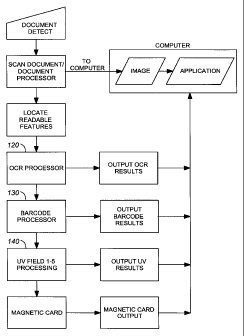
Figure 5 is a flow chart showing the steps performed by document controller
firmware run by the document reader. The document controller software controls
the
activities performed by the document reader and, in doing so, it determines
which software
components are run in order to process input an produce the required output.
As such, the
functionality of the document reader is limited to documents which have a
configuration
falling within the scope of the controller software (i.e. to those which can
be processed
thereby) and, thus, the document reader is effectively matched to a
predetermined type of
document.
2 o When the presence of a document is detected by the document detector 80 of
the
reader, the document is scanned by exciting the IR, visible and UV LED bank so
as to
illuminate the MRZ with one or more of visible, IR and UV illumination,
respectively. As
stated above, these differing illumination frequency LED banks are normally
excited on a
sequential basis but can be excited on a directed (individual) basis as
desired. For each
2 s scanned (i.e. visible) image appearing in the MRZ of the document as a
result of the
applied illumination, the image is captured by the image sensor (i.e. the CCD
40 in Figure
- 19 -
CA 02375577 2002-03-07
4) of the reader and forwarded to a host computer for processing by one or
more
applications running on the host computer (as desired). A feature locator
component of
the document controller software locates and identifies the individual
features (indicia) of
the document image. Specifically, with reference to Figure 2, it locates and
identifies the
following indicia of the machine readable zone of the document: the visible
photograph 51;
to the barcode 52; the OCR text 53, 54; and, the UV visible fields 1-4.
Different types of features are processed differently by individual software
components configured appropriately to take the desired processing steps. An
OCR
software component 120 processes the OCR features 53, 54 according to
conventional
15 processing steps whereby the lines of OCR-B characters of these features
are recognized
and interpreted. As is known to persons skilled in the art, the OCR software
component
preferably includes processing steps for context and format checking to
determine possible
errors in the identified characters. The OCR software component 120 outputs
the
interpreted character set determined by it and this output is forwarded to a
host computer
2 o for display on a monitor and/or further processing as desired. Optionally,
the output
characters could instead be directly forwarded to an electronic display (such
as, for
example, if associated processing by other software applications is not
desired).
A PDF software component 130 isolates, analyses and decodes the PDF417
2 s barcode feature 52. A UV field software component 140 determines the
images of the UV
fields 1-5 and, where applicable, processes these images using the foregoing
OCR and
- 20 -
CA 02375577 2002-03-07
s PDF software components. A magnetic card reader software component is also
preferably
provided for processing data read by a magnetic card reader 100 of the reader.
As for the
output of the OCR component, the outputs of each of these software components
is
forwarded to the host computer for further processing and/or display on a
monitor.
1 o The individual optoelectronic system and software processing functions
utilised in
the foregoing described embodiment are well understood by those skilled in the
art. 1t is
to be understood by a person skilled in the field of optoelectronics and image
processing
that a variety of other implementations may be devised for substitution and
such persons
are expected to be able to apply the present invention to implement various
applications
1 s of the same.
Consequently, it is to be understood that the particular embodiment described
herein by way of illustration is not intended to limit the scope of the
invention claimed by
the inventors which is defined by the appended claims.
- 21 -