Note: Descriptions are shown in the official language in which they were submitted.
CA 02376562 2002-03-13
FY.50011 CAO PATENT
LUBRICATION SYSTEM FOR SNOWMOBILE ENGINE
Background of the Invention
Field of the Invention
The present invention generally relates to an improved engine for land
vehicles.
More specifically, the present invention relates to an improved lubrication
system layout
for an engine that results in a generally smaller engine, and thus a generally
smaller
vehicle body.
Description of the Related Art
Snowmobiles are powered by internal combustion engines that are mounted
within a substantially enclosed engine compartment forward of the rider's
seat. The
engine compartment typically is defined within a cowling and is generally
relatively
small.
Internal combustion engines generally have a lubrication system to reduce
friction
between moving components, which causes heat and wear of the moving components
of
the engine. The lubrication system sometimes includes a lubricant pump for
supplying
lubricant to the various moving components, a lubricant cooler for removing
heat from
the lubricant, and a lubricant filter for removing debris from the lubricant.
Typically, the
lubricant pump is mounted on the opposite side of the engine from the
lubricant cooler
and the lubricant filter.
Positioning the lubricant filter and the lubricant cooler on the opposite side
of the
engine from the lubricant pump is disadvantageous for snowmobile applications
because
it increases the distance between these components, which increases the size
of the
engine. Also, a more complex system of conduits is required to route the
lubricant to
these components and to the moving engine components.
Summary of the Invention
Thus, an engine layout that can reduce the engine size and reduce the
complexity
of the lubrication system is desired.
Accordingly, one aspect of the present invention involves a snowmobile that
has a
frame assembly that defines a longitudinal vertical plane and a transverse
vertical plane.
An internal combustion engine is mounted to the frame assembly generally along
the
transverse vertical plane of the frame assembly. The internal combustion
engine includes
a cylinder block that defines a cylinder bore and a crankcase connected to the
cylinder
-1-
CA 02376562 2002-03-13
block. The crankcase defines a crankcase chamber. The crankcase has a
crankshaft
journaled therein that rotates about a crankshaft axis. The engine also has a
piston
reciprocally positioned in the cylinder bore that drives the crankshaft. The
engine also
has a lubrication system that includes a lubricant pump unit mounted in the
crankcase
chamber, a lubricant cooler, and a lubricant filter. The lubricant pump unit
is mounted at
a location offset from the crankshaft axis. The lubricant pump unit also has a
lubricant
pump that is rotatable about a lubricant pump axis. At least one of the
lubricant cooler
and the lubricant filter is positioned on the same side of the engine as the
lubricant pump
unit.
Another aspect of the present invention involves an internal combustion engine
that includes a crankcase and a cylinder block that defines a cylinder bore.
The crankcase
is connected to the cylinder block and defines a crankcase chamber. A
crankshaft is
journaled in the crankcase and is rotatable about a crankshaft axis. A piston
that is
reciprocally positioned in the cylinder bore drives the crankshaft. The engine
also has a
lubrication system that includes a lubricant cooler, a lubricant filter, and a
lubricant pump
unit. The lubricant pump unit is mounted in the crankcase chamber at a
location offset
from the crankshaft axis. The lubricant pump unit includes a lubricant pump
that is
rotatable about a lubricant pump axis. At least one of the lubricant cooler
and the
lubricant filter is positioned on the same side of the engine as the lubricant
pump unit.
Brief Description of the Drawings
These and other features, aspects and advantages of the present invention will
be
better understood with reference a preferred embodiment, which is illustrated
in the
accompanying drawings. The illustrated embodiment is merely exemplary and is
not
intended to define the outer limits of the scope of the present invention. The
drawings of
the illustrated arrangement comprise seventeen figures.
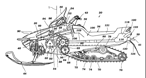
Figure 1 is a side elevation view of a one embodiment of a snowmobile with
certain portions broken away and other internal portions shown in hidden line
to better
illustrate certain features, aspects and advantages of the present invention.
Figure 2 is a schematic top, front, and side perspective view of one
embodiment of
an engine of the snowmobile of Figure 1.
Figure 3 is a schematic view of a lubrication system of the engine of Figure
2.
Figure 4 is a cross-section view of the engine of Figure 2 taken along the
line 4- 4
shown in Figure 7.
-2-
CA 02376562 2002-03-13
Figure 5 is a cross-section view of the engine of Figure 2 taken along the
line 5 - 5
shown in Figure 4.
Figure 6 is a cross-section view of the engine of Figure 2 taken along the
line 6 - 6
shown in Figure 7.
Figure 7 is a cross-section view of the engine of Figure 2 taken along the
line 7 - 7
shown in Figure 4.
Figure 8 is a cross-section view of the engine of Figure 2 taken along the
line 8 - 8
shown in Figure 7.
Figure 9 is a cross-section view of the engine of Figure 2 taken along the
line 9 - 9
shown in Figure 4.
Figure 10 is a cross-section view of the engine of Figure 2 taken along the
line 10
- 10 shown in Figure 5.
Figure 11 is a cross-section view of the engine of Figure 2 taken along the
line 11
- 11 shown in Figure 8.
Figure 12 is a side elevation view of one embodiment of an engine cooling
system
of the snowmobile of Figure 1.
Figure 13 is a top view of the cooling system of Figure 12.
Figure 14 is a top view of a lubricant cooler of the engine of Figure 2
showing the
connection of the cooler to the cooling system of Figures 12 and 13.
Figure 15 is a side elevation view of one embodiment of a lubricant pump unit
with certain portions broken away and other internal portions shown in hidden
line to
better illustrate certain features, aspects and advantages of the present
invention.
Figure 16 is a bottom view of the lubricant pump unit of Figure 15.
Figure 17 is a side elevation view of the lubricant pump unit of Figure 15.
Detailed Description of the Preferred Embodiment
With reference now to Figure 1, a snowmobile featuring certain features,
aspects
and advantages of the present invention will be described. The snowmobile,
indicated
generally by the reference numeral 20, is an environment for which many
features,
aspects and advantages of the present invention have been specially adapted.
Nevertheless, certain features, aspects and advantages of the present
invention can be used
with other vehicles, such as all-terrain vehicle and watercrafft.
The snowmobile 20 generally comprises a frame assembly 22 that carries a
number of other components of the snowmobile 20. A forward body cover 24 is
disposed
-3-
CA 02376562 2002-03-13
over a forward portion of the frame assembly 22. The forward body cover 24
defines, in
part, an engine compartment 26 in which an engine 28 is mounted. The engine 28
is
mounted to the frame assembly 22 in any suitable manner. The engine 28 and its
associated systems and components will be described in greater detail below in
connection with Figures 2-17.
A windshield 30 is disposed over a mid-portion of the body cover 24. The
windshield 30 provides some degree of protection for the riders from wind and
other
elements during operation of the snowmobile 20. Rearward of the windshield 30,
a fuel
tank 32 is mounted to the frame assembly 22 in a manner that allows the body
cover 24
and the fuel tank 32 to blend together for aesthetic reasons.
Rearward of the fuel tank 32, a seat 34 is mounted to the frame assembly 22. A
right-side step, or foot-rest 36, is attached to the right-hand side of the
frame 22 of the
snowmobile 20. A left-side step, or foot-rest 38, is attached to the left-hand
side of the
frame 22 of the snowmobile 20. As used herein, "right," "right-hand," "right-
side,"
"left," "left-hand," and "left-side" are defined from the perspective of a
rider on the seat
34 facing forward. Rearward of the seat 34 is positioned a grab bar 39 that
comprises a
grabbing portion 41 that can be used to raise a rear portion of the snowmobile
for turning
and maneuvering when the snowmobile is not being ridden. While the illustrated
grab bar
39 is generally U-shaped and is mounted in a generally horizontal manner,
other forms of
grab bars can be used. For instance, the grab bar 39 can be loops,
semicircular, vertical or
inclined in orientation. In short, any suitable grab bar construction can be
used.
Forward of the seat 34 and the fuel tank 32 is a steering handle assembly 42.
The
handle assembly 42 can carry appropriate controls and can be coupled to a pair
of front
skis 44 in any suitable manner. Manipulation of the handle assembly 42 causes
the
direction of the snowmobile 20 to be altered in a known fashion. The skis 44
are mounted
to the frame assembly 22 though a front suspension assembly 46. Any suitable
front
suspension assembly 46 can be used.
The engine 28 in the illustrated arrangement is an inclined L-4 four-cycle
engine
that is mounted transversely within the engine compartment 26. In other words,
the
illustrated engine 28 comprises four cylinder bores that extend side-by-side
across a width
of the snowmobile 20. The cylinder bores each comprise a center axis 0 that is
inclined
relative to vertical. In some arrangements, engines having differing numbers
of cylinder
bores, different cylinder bore configurations (e.g., V, opposing, etc.),
different
-4-
CA 02376562 2002-03-13
orientations (e.g., vertical) and different operating principles (e.g., two-
stroke, rotary, etc.)
can be used.
The engine 28 also comprises an output shaft 50. The output shaft 50 drives a
transmission, which is a continuously variable transmission 52 in the
illustrated
arrangement. Other transmissions also can be used. In the illustrated
arrangement, the
output shaft 50 rotates a drive pulley 54. The output shaft 50 and the drive
pulley 54 can
be connected together through a clutch, a centrifugal clutch, a sprag clutch
or can be
directly connected together.
The drive pulley 54 powers a driven pulley 56 with a v-belt 58 in the
illustrated
arrangement. In some configurations, a drive chain can be used in place of the
v-belt 58.
Other arrangements also can be used. The driven pulley 56 is connected to and
rotates
about a transfer shaft 60. In the illustrated arrangement, the transfer shaft
60 carries a
sprocket (not shown) at the end opposite to the driven pulley 56. The sprocket
is
connected to a further sprocket that is camed by a drive shaft 62.
The drive shaft 62 powers a drive unit 64. The drive unit 64 generally
comprises a
plurality of drive wheels 68. The drive wheels 68 provide a motive force to a
drive belt
70, which is commonly used in the snowmobile industry.
With continued reference to Figure 1, the drive belt 70 is guided around a
preferred path on a pair of slide rails 72, a plurality of suspension wheels
74 and main rear
suspension wheels 76. The slide rails 72 preferably support the suspension
wheels 74 and
the main rear suspension wheels 76. An idler roller 78 preferably is mounted
to the frame
assembly 22 and helps to define the preferred path for the drive belt 70. As
is known in
the snowmobile industry, these components can be mounted to the frame assembly
with a
rear suspension system 80. Any suitable rear suspension system 80 can be used
and
certain portions of the rear suspension system 80 have been schematically
illustrated in
the illustrated arrangement.
Many of the above-described components are generally conventional and can be
arranged and configured in any suitable manner. Additionally, the above-
described
components can be replaced by other suitable components where desired. Any
details
omitted to this point have been considered well within the design knowledge of
those of
ordinary skill in the art.
With continued reference to Figure 1, air is drawn into the engine compartment
26
through suitable air passages. In some arrangements, the air is drawn through
ventilation
-5-
CA 02376562 2002-03-13
openings 90 formed in the body cover 24. The air drawn or forced into the
engine
compartment 26 circulates about the engine 28 and related drive components to
help cool
the engine 28 and the related drive components.
The air also is drawn into an air induction system that includes an air intake
box
92. The air intake box 92 is disposed forward of the engine 28 in the
illustrated
arrangement. The air intake box 92 can be mounted to the frame assembly 22 in
a manner
that will be described. An air inlet 93 into the air intake box 92 can extend
upward into a
lower surface of the air intake box 92.
A set of intake runners 94 extends between the illustrated air intake box 92
and the
engine 28. Preferably, a charge former 96 is disposed along each of the intake
runners 94.
Advantageously, the intake runners 94 extend directly rearward to the engine
28 rather
than wrapping around the engine 28 and mating with a rearward-facing surface
of the
engine 28. The charge formers 96 preferably correspond to each cylinder bore.
In some
arrangements, a single charge former can be used upstream of a separation
point for
runners extending to individual cylinder bores. In addition, in the
illustrated arrangement,
the engine 28 is carbureted. In some arrangements, the charge formers 96 can
be fuel
injectors that are mounted for direct injection, indirect injection or port
injection. The air-
fuel charge provided in this manner is combusted within the engine as
discussed in more
detail below.
The combustion byproducts then are exhausted through a suitable exhaust system
100. In the illustrated arrangement, the exhaust system 100 extends directly
rearward
from the engine 28. In this manner, an exhaust runner 102 that extends
rearward from the
engine can be tuned to the engine for improved engine performance.
Additionally, the
length of each runner 102 can be lengthened prior to merging together with any
other
runners such that pulse effects on adjoining cylinder bores can be reduced. In
some
arrangements, an attenuation chamber or passage between two or more runners
can be
used to reduce the effect of reflected pressure pulses in the exhaust system.
With continued reference to Figure 1, the exhaust system 100 preferably
comprises the exhaust runners 102 that correspond to each cylinder bore and
that extend
generally rearward from the engine. Each exhaust runner 102 is coupled to an
exhaust
discharge pipe 106 that is joined to the engine. In some arrangements, a
single manifold
can be used while in others each of the exhaust discharge pipes 106 are
individually
-6-
CA 02376562 2002-03-13
joined to the engine. At least two of the runners 102 join at a merge location
(not shown)
and the merged flow passes through a manifold pipe 116.
The manifold pipes 116 extend rearward to a silencer box 118. The silencer box
118 provides an enlarged volume into which the exhaust can flow. Exhaust
energy is
dissipated within the silencer box 118 and the noise level of the exhaust can
be decreased.
In the illustrated arrangement, the silencer box 118 is disposed below a
portion of the seat
34 that is rearward of a rider section 121 of the seat.
A pair of exhaust pipes 120 extends rearward from the silencer box 118. In
some
arrangements, a single exhaust pipe 120 can extend from the silencer box 118.
Other
numbers of exhaust pipes also can be used. One end of each of the exhaust
pipes 120
preferably defines an ultimate exhaust discharge 122 from the snowmobile 20
such that
the exhaust gases are discharged into the atmosphere at this location. As
illustrated in
Figure 1, the exhaust pipes 120 can extend upwardly and rearwardly from the
silencer box
118 while, in another arrangement, shown in hidden lines, the exhaust pipes
120 can
extend downward to a location forward of a protective flap 124. Preferably,
the exhaust
pipes 120 terminate at a location forward of the grab portion 41 of the grab
bar 39
With reference now to Figures 2-17, the engine 28 and some systems and
components thereof will be described in greater detail. The engine 28 includes
a cylinder
block 204 that defines four combustion bores 208 spaced from each other
transversely
across the snowmobile 20. As mentioned above, each of the cylinder bores 208
has a
cylinder bore axis 0 that is slanted or inclined at an angle from an imaginary
vertically-
oriented plane T that is transverse to the snowmobile 20 so that the engine 28
can be
shorter in height (see Figure 1). The cylinder bore axis 0 is the same for
each of the
cylinder bores 208 in the illustrated embodiment. A pistons 212 reciprocate
within each
of the cylinder bores 208.
A cylinder head 216 is affixed to the upper end of the cylinder block 204 to
close
respective upper ends of the cylinder bores 208 and thus define combustion
chambers 220
with the cylinder bores 208 and the pistons 212. The cylinder head 216 defines
intake
ports 254 that communicate with the associated combustion chambers 220 and
also
communication with the air induction system discussed above. The cylinder head
216
also defines exhaust ports 266 that communicate with the associated combustion
chambers 220 and also communicate with the exhaust system 100 discussed above.
The
-7-
CA 02376562 2002-03-13
ports 254, 266 and their function in controlling the introduction and
withdrawal of gasses
from the combustion chambers 20 will be discussed in more detail below.
With reference to Figures 2, 6, and 7, a crankcase member 224 is affixed to
the
lower end of the cylinder block 204 to define a crankcase chamber 225. In the
illustrated
arrangement, the crankcase member 224 includes an upper portion 226 and a
lower
portion 227 joined along the plane P - P (see Figures 6 and 7). The crankcase
member
224 also defines a breather inlet hole 228 that communicates with the
crankcase chamber
225. The breather inlet hole 228 also communicates with at least one breather
chamber
229 in a manner discussed more fully below.
With reference to Figure 7, a crankshaft 232 having a plurality of journal
portions
235 and a throw defined, in part, by two adjacent crank webs 234 is rotatably
connected
to the pistons 212 through the connecting rods 238. A through-hole 233 is
provided that
extends across a diameter of the crankshaft 232 at each of the journal
portions 235. Each
of the connecting rods 238 is rotatably coupled to the crank web 234 through a
connecting
pin 239. That is, the connecting rods 238 are rotatably coupled with the
pistons 212 and
with the throws of the crankshaft 232. The crankshaft 232 is also journaled in
the
crankcase member 224 at the journal portions 235 by bearings (not shown). A
crankcase
cover 236 is affixed to the lower end of the crankcase member 224, extends
under the
crankshaft 232 and encloses the crankcase chamber 225. The crankcase cover 236
forms,
at least in part, a shallow reservoir 237.
The cylinder bore axes 0 of the engine 28 are inclined with respect to the
vertical
direction. As a result, lubricant which drains downward through the engine
body to the
crankcase cover 237 tends to collect in the lower most region of the engine
body. As
discussed in more detail below, the lubricant that collects in the reservoir
237 is
reintroduced into the lubrication system for continued lubrication of the
engine 28.
A drive gear 240 is mounted proximate an end of the crankshaft 232. A driven
gear 242 is mounted proximate an end of the output shaft 50 and is positioned
to be
driven by the drive gear 240. A crankshaft cover 250 that covers an end of the
crankshaft
232, the drive gear 240, and the driven gear 242 is provided on a lateral side
of the
crankcase member 224. As described more fully below, rotation of the
crankshaft 232
drives the output shaft 50 at an angular speed determined, in part, by the
size of each of
the drive gear 240 and the driven gear 242, as is known.
-8-
CA 02376562 2002-03-13
The cylinder block 204, the cylinder head member 216, the crankshaft cover
250,
and the crankcase member 224 together define an engine body 252. The engine
body 252
preferably is made of an aluminum-based alloy. In the illustrated embodiment,
the engine
body 252 is oriented in the engine compartment 26 so as to position the
crankshaft 232
generally perpendicular to an imaginary generally vertical center plane of the
snowmobile
20, i.e., to extend generally in the transversely across the snowmobile 20.
Other
orientations of the engine body 252, of course, are also possible (e.g., with
a longitudinal
or vertically-oriented crankshaft).
As discussed above, the engine 28 includes an air induction system configured
to
guide air into the combustion chamber 220. In the illustrated embodiment, the
air
induction systems include the intake ports 254 defined in the cylinder head
member 216.
Intake valves 258 are provided to selectively connect and disconnect the
intake ports 254
with the combustion chambers 220. That is the intake valves 258 selectively
open and
close the intake ports 254.
As discussed above, the charge former 96 is in communication with the air
intake
box 92 and is also in communication with the fuel system to provide an air
fuel mixture
appropriate for running conditions of the engine 28 in a known manner. As
such, the
charge former 96 delivers the mixed air fuel charge to the combustion chamber
220 when
intake ports 254 are opened to the combustion chamber 220 by the intake valves
258.
The engine 28 also includes an ignition system. With reference to Figure 2,
spark
plugs 262, at least one for each combustion chamber 220, are affixed to the
cylinder head
member 216. Electrodes, which are defined at one end of the spark plugs 262,
are
exposed to the respective combustion chambers 220. Sparks plugs 262 preferably
are
fired in a conventional manner. The air/fuel charge is combusted during every
combustion stroke accordingly.
The exhaust system 100, as discussed above in connection with Figure 1,
discharges burnt charges, i.e., exhaust gasses, from the combustion chambers
220. With
reference to Figure 6, the exhaust system includes the exhaust ports 266 for
each of the
combustion chambers 220. Exhaust valves 270 are provided to selectively
connect and
disconnect exhaust ports 266 with the combustion chambers 220. That is, the
exhaust
valves 270 selectively open and close the exhaust ports 266. The exhaust ports
266
communicate with the exhaust runner 102 and the exhaust gasses are eliminated
in a
manner described above.
-9-
CA 02376562 2002-03-13
The engine 28 has a valvetrain for actuating the intake and exhaust valves
258,
270. In the illustrated embodiment, a double overhead cam-type valvetrain is
employed.
That is, an intake camshaft 278 actuates the intake valves 258 and exhaust
camshaft 282
separately actuates the exhaust valves 270. The intake camshaft 278 extends
generally
horizontally over the intake valves 258 transversely to the imaginary vertical
center plane
of the snowmobile 20. Likewise, the exhaust camshaft 282 also extends
transversely
generally horizontally over the exhaust valves 270.
Both the intake and the exhaust camshafts 278, 282 are joumaled by the
cylinder
head member 216 with a plurality of camshaft caps (not shown). The camshaft
caps
holding camshafts 278, 282 are fixed to the cylinder head member 216. A
cylinder head
cover member 286 extends over the camshafts 278, 282 and the camshaft caps,
and is
affixed to the cylinder head member 216 to define a camshaft chamber.
The intake camshaft 278 has cam lobes 290 associated with the respective
intake
valves 258, and exhaust camshaft 282 has cam lobes 294 associated with the
respective
exhaust valves 270. The intake and exhaust valves 258, 270 normally close the
intake
and exhaust ports 254, 266 by a biasing force of springs. When the intake and
exhaust
camshafts 278, 282 rotate, the cam lobes 290, 294 push the respective valves
258, 270 to
open the respective ports 254, 266 by overcoming the biasing force of the
springs. The
air, thus, can enter the combustion chamber 220 when intake valves 258 open.
In the
same manner, the exhaust gasses can move out from the combustion chamber 220
when
the exhaust valves 270 open. The crankshaft 232 preferably drives the intake
exhaust cam
shafts 278, 282 via a valvetrain drive in a known manner.
In operation, ambient air enters the engine cavity 26 through ventilation
openings
90 defined in the cover 24. The air is then introduced into a plenum chamber
defined by
the intake box 92 through the air inlet 93. The air is drawn into charge
formers 96. The
majority of the air in the intake box 92 is supplied to the combustion
chambers 220.
The charge formers 96 regulate an amount of air permitted to pass the
combustion
chambers 220 in a known manner, e.g., with throttle valves. The opening angles
of the
throttle valves are controlled by the rider via throttle lever and thus
controls the air flow
across the valves. The air hence flows into the combustion chambers 220 when
the intake
valves 258 open. At the same time, the charge formers 96 introduce an air/fuel
mixture
into the intake ports 254 under the control of an electronic control unit, or
ECU. The
air/fuel charges are thus formed and delivered to the combustion chambers 220.
-10-
CA 02376562 2002-03-13
The air/fuel charges are fired by the spark plugs 262 under the control of the
ECU.
The burnt charges i.e., exhaust gasses, are discharged to the atmosphere
surrounding the
snowmobile 20 through the exhaust systems 100 as discussed above.
The combustion of the air/fuel charges causes the pistons 212 to reciprocate
and
thus causes the crankshaft 232 to rotate about a crankshaft axis "A." The
crankshaft 232
drives the output shaft 50, which in turn drives the transfer shaft 62. The
rotation of the
transfer shaft 62 is transmitted to the drive belt 70. The rider steers the
skis 44 by the
handle bar 42. The snowmobile 20 thus moves as the rider desires.
The engine 28 also includes other components relating to engine operations.
With
reference to Figure 7, the engine 28 employs a flywheel magneto or AC
generator 318 as
one of such engine components. The flywheel magneto 318 is connected to the
crankshaft 232 by a one-way clutch 320, which, as is known, permits rotation
of the
flywheel magneto 318 in one direction only. The flywheel magneto 318 generates
electric power that is used for the engine operation as well for electrical
accessories
associated with snowmobile 20. The flywheel magneto 318 is located on one
lateral side
of the engine 28 and is enclosed by a flywheel magneto housing 322. A starter
motor 326
is selectively connectable to the crankshaft 232 to rotate the crankshaft 232
for starting
the engine 28. In one embodiment, the starter motor 326 is selectively
connectable to the
crankshaft via a starter motor gear 327. The starter motor 326 may be powered
by a
battery (not shown) that is mounted to the snowmobile 20.
With reference to figures 2, 4 and 5, the engine 28 of the snowmobile 20 also
comprises a cooling system 398 and a lubrication system 400 that are driven by
an
auxiliary shaft 350 located in the crankcase 224. The auxiliary shaft 350
includes a
coolant pump drive shaft 390 and a lubricant pump drive shaft 394 that are
joined at a
coupling 396. A lubricant pump assembly 353 that includes a primary lubricant
pump
354 and a secondary lubricant pump 355 preferably is configured to receive the
lubricant
pump drive shaft 394, as discussed below. A coolant pump 504 preferably is
configured
to receive the coolant pump drive shaft 390. The lubrication system 400, which
is a dry-
sump type lubrication system, will be discussed in greater detail below. The
cooling
system 398 will be discussed in more detail below in connection with Figures
12-14.
The auxiliary shaft 350 is preferably driven by the output shaft 50 through an
auxiliary drivetrain 362. The auxiliary drivetrain 362 includes an auxiliary
shaft sprocket
366, an output shaft sprocket 370, and an auxiliary flexible transmitter 374.
The auxiliary
-11-
CA 02376562 2002-03-13
shaft sprocket 366 is connected to the auxiliary shaft 350. In the illustrated
embodiment,
the flexible transmitter 374 is a chain. The auxiliary flexible transmitter
374 is wound
around the auxiliary shaft sprocket 366 and the output shaft sprocket 370. One
of
ordinary skill in the art will appreciate that a belt and pulley arrangement
can also be used
in place the flexible transmitter 374 and the sprockets 366, 370. When the
output shaft 50
rotates, the output shaft sprocket 370 drives the auxiliary shaft sprocket 366
via the
flexible transmitter 374, and thus the auxiliary shaft 350 also rotates. This
rotational
motion drives the lubricant pumps and the coolant pump as discussed below.
A lubricant pump housing 378 is provided on the crankcase member 224 to at
least partially house the lubricant pump unit 356. A coolant pump housing 382
is
provided proximate the lubricant pump housing 378 to at least partially house
the coolant
pump 504. A coolant pump housing cover 386 is provided on one side of the
crankcase
224 to at least partially enclose the coolant pump 504 and the auxiliary shaft
350.
The lubrication system 400 includes the shallow reservoir 237, the lubricant
pump
unit 356, and a lubricant supply, such as a lubricant tank 405. The lubricant
pump unit
356 includes the lubricant pump assembly 353, which includes the primary
lubricant
pump 354 and the secondary lubricant pump 355. The lubricant pump unit 356
also
includes a lubricant strainer 401 that includes a lubricant intake port 402, a
lubricant
check valve 403, and a lubricant relief valve 404. In one embodiment, the
lubricant relief
valve 404 includes a spring 404a that can be displaced to increase the volume
within the
relief valve 404. More details of the lubricant pump unit 356 are discussed
below in
connection with Figures 15 - 17.
The lubricant supply 405 is positioned within the cover 24 of the snowmobile
20
in one embodiment. In another embodiment, the lubricant supply 405 is a
lubricant pan
which may be positioned within the engine 28. A lubricant supply passage 406
connects
the primary lubricant pump 354 of the lubricant pump unit 356 to the lubricant
supply 405
and provides fluid communication therebetween. Lubricant that collects in the
shallow
reservoir 237 is drawn up by the primary lubricant pump 354 (as indicated by a
lubricant
flow line "a" in Figure 5) and delivered to the lubricant supply 405 through
the lubricant
supply passage 406 (as indicated by a lubricant flow line "b," a lubricant
flow line "c,"
and a lubricant flow line "d"). A lubricant passage 412 provides fluid
communication
between the lubricant supply 405 and the secondary lubricant pump 355 of the
lubricant
pump unit 356. The secondary lubricant pump 355 draws lubricant from the
lubricant
-12-
CA 02376562 2002-03-13
supply 405 through the lubricant supply passage 412 as indicated by a
lubricant flow line
"e" and a lubricant flow line "f." The secondary lubricant pump 353 then
supplies the
lubricant to many of the components of the engine 28 through a series of
lubricant supply
passages.
The supply of the lubricant is regulated by the check valve 403, which
prevents
backflow of the lubricant to the lubricant pump assembly 353, and the relief
valve 404.
As discussed above, the relief valve 404 includes the spring 404a, which can
be
compressed by a portion of the relief valve 404 to increase the volume in the
relief valve
404. By increasing the volume of the valve 404, the fluid pressure in the
system
downstream of the secondary pump 355 is reduced.
With reference to Figure 3, the lubrication system 400 also comprises a
lubrication
cooler 420, a lubrication filter 424, a lubricant main gallery 428, and a
hydraulic pressure
sensor 432. The hydraulic pressure sensor 432 provides lubricant pressure
information to
the ECU and/or the rider. A lubricant supply passage 436 connects the
lubricant pump
unit 356 to the lubricant cooler 420 and provides fluid communication
therebetween.
Lubricant is delivered by the lubricant pump unit 356 into the passage 436 and
thereby to
the lubricant cooler 420, as indicated by a lubricant flow line "g." The
lubricant cooler
420 includes a heat exchanger 422 and a heat exchange passage 423. Lubricant
that
enters the lubricant cooler 420 flows through the heat exchange passage 423
(as indicated
by a lubricant flow line "i") and is cooled therein. A lubricant passage 440
provides fluid
communication between the lubricant cooler 420 and the lubricant filter 424.
Thus,
lubricant is directed from the lubricant cooler 420 to the lubricant filter
424, as indicated
by a lubricant flow line "j." A lubricant supply line 444 provides fluid
communication
between an outlet of the lubricant filter 424 and the main gallery 428 (as
indicated by a
lubricant flow line "k").
In one embodiment, the lubricant cooler 420 and the lubricant filter 424 are
positioned on the same side of the engine as the lubricant pump unit 356. That
is, the
lubricant cooler 420, the lubricant filter 424, and the lubricant pump unit
356 are all
positioned on a forward-facing side of the engine (see Figure 2). Preferably,
the lubricant
pump unit 356, the lubricant cooler 420, and the lubricant filter 424 are
arranged
transversely across the engine 28 at about the same elevation. In another
embodiment, the
lubricant pump unit 356 and the lubricant cooler 420 are positioned on the
same side of
the engine 28, e.g., the forward-facing side. In another embodiment, the
lubricant pump
-13-
CA 02376562 2002-03-13
unit 356 and the lubricant filter 424 are positioned on the same side of the
engine 28. By
positioning at least two of the lubricant pump unit 356, the lubricant cooler
420, and the
lubricant filter 424 on the same side of the engine 28, the engine can be
reduced in size
and can more easily fit into the engine compartment 26. In addition, by
positioning these
components as described herein, the complexity of the lubrication system 400
can be
reduced, e.g., by allowing a less complex system of lubricant supply passages.
A lubricant supply passage 448 branches off from the lubricant passage 444 and
provides fluid communication between the passage 448 and the output shaft 50.
Preferably a first orifice 452 and a second orifice 456 are located in the
lubricant supply
passage 448 to regulate the lubricant pressure (or lubricant flow rate) within
the passage
448. This provides an appropriate amount of lubricant to the bearings of the
output shaft
50, which are ball bearings in one embodiment.. Lubricant flow through the
lubricant
supply passage 448 is illustrated by a lubricant flow line "r" (see Figure 5).
It should be
recognized that fewer than two such orifices could be provided in the passage
448 and
that other approaches can be provided that regulate lubricant flow in the
lubricant supply
passage 448
The lubricant main gallery 428 provides lubricant to various components of the
engine 28. Lubricant flow in the main gallery 428 is indicated by the
lubricant flow line
"1." The hydraulic pressure sensor 432 advantageously is in fluid
communication with the
lubricant main gallery 428. A plurality of lubricant supply passages 460
branch off the
lubricant main gallery 428 and are in fluid communication with the journal
portion 235 of
the crankshaft 232 to provide lubricant thereto. Each through-hole 233 in the
journal
portions 235 connects the passages 460 to a lubricant supply passage 464 that
directs
lubricant into the cylinder bores 208 and to a lubricant supply passage 468
that directs
lubricant to the connecting pins 239.
A lubricant passage 472 branches off the lubricant passage 460 nearest to the
rotor
318 to supply lubricant to the rotor 318 and to the journal portion 235 of the
crankshaft
232 that is closest to the rotor 318. Lubricant in the passage 472 is
delivered through a
passage 476 to a lubricant port 480. A port 484 is provided in fluid
communication with
the passage 472 to supply lubricant to a bushing 486 positioned around the
journal portion
235 of the crankshaft 232 that is closest to the rotor 318. Th
A valvetrain lubricant passage 488 also branches off the main gallery 440.
Lubricant flow in the lubricant passage 488 is indicated by a lubricant flow
line "m" (see
-14-
CA 02376562 2002-03-13
Figures 4, 7, and 9). The valvetrain lubricant passage 488 bifurcates into a
first branch
490 and a second branch 492. The first branch 490 carries lubricant to a
plurality of
lubricant ports 494 that communicate with the exhaust camshaft 282 to
lubricate the
camshaft 282. The second branch 492 carries lubricant to a plurality of
lubricant ports
496 that communicate with the intake camshaft 278 to lubricate the camshaft
278.
As discussed above, the engine 28 also includes the cooling system 398. With
reference now to Figures 12 - 14, the cooling system 398 is connected to the
frame 22
and to the engine 28 of the snowmobile 20. In one embodiment, the cooling
system 398
includes several coolant branches driven by the coolant pump 504. The coolant
pump
504 has a coolant inlet port 508 and a coolant outlet port 512.
A first cooling system branch begins at the outlet port 512 and includes a
coolant
passage 516 that extends between the outlet port 512 and the engine 28. A
portion of the
coolant that is supplied by the coolant pump 504 is provided through the
coolant passage
516 and is circulated through the engine body to cool various components
thereof. A
plurality of coolant passages 520 extend between the engine 28 and a coolant
merge
passage 524. The coolant merge passage 524 is connected to a temperature
regulator 528
through which the coolant in the cooling system 398 flows. A coolant passage
532
extends between the temperature regulator 528 and the inlet port 508 of the
coolant pump
504. When the engine 28 is first started and is, therefore, cold, the
temperature regulator
528 routes most of the coolant through the first branch of the cooling system
398. As the
temperature of the engine 28 rises, at least a portion of the coolant is
circulated through a
second coolant branch.
The second coolant branch includes a coolant supply, such as the coolant tank
536, a right-side heat exchanger 540, a left-side heat exchanger 544, the
coolant pump
504 and coolant passages interconnecting each of these components. A coolant
passage
548 that extends between the temperature regulator 528 and the coolant tank
536 carries
coolant from the first coolant branch to the coolant tank 536. A coolant
passage 552 that
extends between the coolant tank 536 and the right-side heat exchanger 540
carries
coolant to the heat exchanger 540. In one embodiment, the heat exchanger 540
is at least
partially located proximate the right-side step 36. The heat exchanger 540
removes heat
from the coolant in a known manner. A coolant passage 556 that extends between
the
right-side heat exchanger 540 and the left-side heat exchanger 544 carries
coolant to the
left-side heat exchanger 544. In one embodiment, the left-side heat exchanger
544 is
-15-
CA 02376562 2002-03-13
located at least partially proximate the left-side step 38. As with the right-
side heat
exchanger 540, the left-side heat exchanger 544 removes heat from the coolant
flowing
therethrough. A coolant passage 560 that extends between the left-side heat
exchanger
544 and the inlet port 508 of the coolant pump 504 carries coolant back to the
coolant
pump 504 for further circulation through the engine 28 and associated
components.
In one embodiment, a third coolant branch is provided in the cooling system
398
to cool the lubricant in the lubrication system 400 of the engine 28. A
coolant passage
564 branches off from the coolant passage 516 and is in fluid communication
with an
inlet side of the lubricant cooler 420. A coolant passage 568 extends from an
outlet side
of the lubricant cooler 420 to the temperature regulator 528 and connects
thereto. A
portion of the coolant from the coolant pump 504 is delivered into the coolant
passage
564. This coolant flows through the lubricant cooler 420, which includes the
heat
exchanger 422 to transfer heat from the lubricant in the lubrication system
400 to the
coolant (see Figure 10). In some running conditions, the lubricant can be
warmed by the
coolant flowing therethrough. After flowing through the lubricant cooler 420,
the coolant
is carried by the coolant passage 568 back to the temperature regulator 528
for further
circulation in the cooling system 398.
In one embodiment, the cooling system 398 includes another branch that
communicates with the charge former 96. A coolant passage 576 branches off
from the
coolant merge passage 524 and connects to an inlet side of a heat exchanger
associated
with the charge former 96. A coolant passage 580 extends from ary outlet side
of the heat
exchanger associated with the charge former 96 to a secondary inlet 584 of the
coolant
pump 504. An auxiliary temperature regulator 588 is provided proximate the
coolant
passage 576 to control the flow of coolant therein.
With reference to Figures 15 - 17, the lubricant pump unit 356 is shown in
more
detail. The lubricant pump unit 356 includes, in one embodiment, a main body
portion
600 having a first side 604 and a second side 608. In one embodiment, the main
body
portion 600 is a housing that at least partially encloses the primary
lubricant pump 354
and the secondary lubricant pump 355. A first cover member 612 is associated
with the
first side 604 of the main body portion 600. In the illustrated embodiment,
the first cover
member 612 is connected to the main body portion 600 by one or more bolts 614
(see
Figures 16 and 17). As discussed above, the lubrication system 400 includes
the strainer
-16-
CA 02376562 2002-03-13
401 and the lubricant intake port 402. In one embodiment, the strainer is
provided in the
first cover member 612.
In one embodiment, the first cover member 612 also includes a lubricant
passage
618 that provides fluid communication between the primary lubricant pump 354
and the
lubricant intake port 402. Lubricant can thus be drawn up by the primary
lubricant pump
354 through the lubricant intake port 402 and through the strainer 401. As the
lubricant is
being drawn through the strainer 401, particles or debris that may collect in
the shallow
reservoir 237 are removed from the lubricant. As discussed above, the
lubricant that is
drawn through the strainer 401 is thus delivered to the lubricant supply 405
through the
lubricant supply passage 406 free of such debris removed by the strainer 401.
The lubricant pump unit 356 also includes, in one embodiment, a second cover
member 616. The second cover member is associated with the second side 608 of
the
main body portion 600. In one embodiment, the second cover member 616 is
connected
to the main body portion 600 by one or more bolts 620 (see Figure 15). Of
course, one or
more of the main body portion 600, the first cover member 612, and the second
cover
member 616 could be combined.
The lubricant pump unit 356 forms an elongated body that extends along a
lubricant pump axis LPA that is coincident with the axis of rotation of the
lubricant pump
drive shaft 394, shown in Figure 15. The main body portion 600 and the first
cover
member 612 are positioned along the lubricant pump axis LPA of the lubricant
pump unit
356. The lubricant pump unit 356 is configured to be mounted in the crankcase
chamber
225 at a location where the lubricant pump axis LPA is offset from the
crankshaft axis
G4A ),
In one embodiment, the lubricant pump unit 356 includes a first mount boss
624, a
second mount boss 628, and a third mount boss 632. The mount bosses 624, 628,
and
632 each include a through-hole to receive a bolt 636, which affix the
lubricant pump unit
356 to the crankcase member 224. In one embodiment, lubricant pump unit 356 is
constructed so that the relief valve 404 extends along an axis generally
parallel to the axis
LPA. With reference to Figure 16, in this embodiment, the relief valve 404 is
positioned
generally between the mount boss 624 and the mount boss 628. The relief valve
404 in
this embodiment is also mounted to a lateral side of a plane extending through
the center
of the through hole of the mount boss 624 and extending perpendicular to the
axis LPA.
-17-
CA 02376562 2002-03-13
In one embodiment, the relief valve 404 is located on the same lateral side of
this plane as
is the first cover member 612.
In one embodiment, the lubricant pump unit 356 is constructed so that the
relief
valve 404 extends along an axis that is generally perpendicular to the axis
LPA. In the
embodiment having a generally perpendicular orientation, the relief valve 404
is located
between the mount bosses 628 and the mount boss 632.
As discussed above, the lubricant pump unit 356 includes a lubricant pump
assembly 353 that includes the primary lubricant pump 354 and the secondary
lubricant
pump 355. The primary lubricant pump 353 is configured to transfer lubricant
that
collects in the shallow reservoir 237 to the lubricant supply 405. In one
embodiment, the
primary lubricant pump 353 has generally more capacity than the secondary
lubricant
pump 354.
Figure 16 shows that the mount bosses can be located on the main body portion
600, the first cover member 612, or the second cover member 616 of the
lubricant pump
unit 356. In the illustrated embodiment, the first mount boss 624 is located
on one lateral
side of the main body portion 600 of the lubricant pump unit 356. The second
mount
boss 628 is located on the opposite lateral side of the lubricant pump unit
356, also on the
main body portion 600. Figure 16 shows that the third mount boss 632 can be
located in
at least two different locations. The mount boss 632 can be located on the
second cover
member 616 or on the main body portion 600. As with the third mount boss 632,
in
another variation, the first mount boss 624 and/or the second mount boss 628
are located
on one of the first cover member 612 or the second cover members 616.
With reference to Figures 4 and 11, the lubricant pump unit 356 in one
embodiment also comprises a rib 640. Air from the crankcase chamber 225 and
from the
region proximate the shallow reservoir 237 communicates with the breather
inlet hole
228. The air is carried through the breather passage 229, which is preferably
a winding
passage, indicated in Figure 4 by the dotted lines 644. The air is separated
thereby from
the lubricant. The breather passage 229 is preferably located above the
auxiliary axis 390.
The air is returned to the air induction system through a breather pipe 648.
Referring to Figure 10, the rib 644 protrudes from an upper surface of the
lubricant pump unit 356. In one embodiment, the rib 644 is positioned on the
main body
portion 600. In another embodiment, the rib 644 is positioned on the first
cover member
612. In another embodiment, the rib 644 is positioned on the second cover
member 616.
-18-
CA 02376562 2002-03-13
The rib 644 is formed adjacent to the breather inlet hole 228 and functions as
an
insulation wall to restrict the outflow of the lubricant by blocking the
breather inlet hole
228. The rib 644 prevents the lubricant from spattering into the breather
inlet hole 228 as
a lubricant mist when the lubricant drips from a hole (not shown) at a bottom
of the crank
chamber 225 toward the crankcase cover 236.
Although the present invention has been described in terms of a certain
embodiment, other embodiments apparent to those of ordinary skill in the art
also are
within the scope of this invention. Thus, various changes and modifications
may be made
without departing from the spirit and scope of the invention. For instance,
various
components may be repositioned as desired. Moreover, not all of the features,
aspects and
advantages are necessarily required to practice the present invention.
Accordingly, the
scope of the present invention is intended to be defined only by the claims
that follow.
-19-
_._..__._.:~.~.-.:_._.__._. . ..:W.,:Y.M._.,..~ .,. ._ .... _._...~
............. _..~~.. .. . ._ ,_ , .,...