Note: Descriptions are shown in the official language in which they were submitted.
CA 02380286 2007-07-10
1
Mechanism for Dropping a Plurality of Balls into Tubulars Used in Drilling,
Completion and Workover of Oil, Gas and Geothermal Wells, and Method of
Using Same
Field of Invention
This invention relates generally to equipment used in the drilling, completion
and workover of subterranean wells and more specifically, to equipment for use
in
oilfield tubulars, for example, in casing strings which are cemented in place
in earth
boreholes drilled into earth formations.
Background
The process of drilling subterranean wells to recover oil and gas from
reservoirs consists of boring a hole in the earth down to the petroleum
accumulation
and installing pipe from the reservoir to the surface. Casing is a protective
pipe liner
within the wellbore that is cemented into place to ensure a pressure-tight
connection
of the casing to the earth formation containing the oil and gas reservoir. The
casing
typically is run a single joint at a time as it is lowered into the wellbore.
Tubulars
other than casing are also used in the drilling, completion and workover of
such
wellbores, for example, drill pipe, completion tubing, production tubing, and
the like.
Moreover, various pieces of downhole equipment utilize balls which, when
dropped
through such tubulars, are activated by such balls, especially by using the
pressure of
fluid pumped from the earth's surface at predetermined
CA 02380286 2001-10-26
WO 01/07748 PCT/US00/11704
2
values to cause such activation. For example, it is well known to drop a ball
from the earth's surface
down through a tubular- onto a seat having a diameter less than the diameter
of the dropped ball. An
increase in the pumped pressure causes some element of the downhole equipment
to be activated.
Without limiting the foregoing, such activation may include the movement of a
sleeve, the opening
or closing of a port, the movement of a valve, the fracturing of a frangible
disk, the release of
elastomeric cement wiper plugs, the control of downhole packers, etc.
The controlled dropping of one or more balls into the top portion of a tubular
at the earth's
surface is therefore very important, both as to the diameter of the ball or
balls, and the timing of the
release of the ball or balls.
BRIEF DESCRIPTION OF THE DRAWINGS
Figure 1: Illustrates an elevated, pictorial view of an example of a downhole
apparatus which can be activated by dropping one or more balls,
followed by increasing the pressure of fluid pumped from the earth's
surface.
Figure 2: Illustrates a two-ball, ball-dropping mechanism, according to the
present invention.
Figure 3: Illustrates a three-ball, ball-dropping mechanism according to the
present invention.
Figure 4: Illustrates a pneumatic circuit which is used to control the ball-
dropping mechanism of Figure 3.
Figure 5: Illustrates a safety pin for ensuring that the smaller ball has to
be
dropped first.
Figure 6: Illustrates a safety pin for ensuring that the smaller ball has to
be
dropped first, then the next larger ball, then the largest ball.
CA 02380286 2001-10-26
WO 01/07748 PCT/US00/11704
3
Figure 1 illustrates, pictorially, the overall apparatus for practicing the
present invention. The
apparatus includes a ball-dropping assembly 64 (shown in more detail in Figure
2), and a cement port
66 which can be used in cementing operations.
Referring now to Figure 2, the ball-dropping apparatus 64 is shown in greater
detail. The
apparatus 54 is a two-ball device, in which two round balls of different
diameters 68 and 70 are
located in a movable ball carrier 72. An air cylinder plunger 74, passing
through an air cylinder seal
75, has a first end attached to the ball carrier 72 and a second end attached
to a piston 76 which
moves within the cylinder 78. A return spring 80 is connected between the
piston 76 and the end
wall of cylinder 78. A second return spring 82 is connected between the other
end of the ball carrier
72 and the other end of the chamber 78a within the interior of the apparatus
64. A pressure source,
either pneumatic or hydraulic (not illustrated), is connected to the port 88
and the same pressure
source, if desired, is connected to the port 90, enabling the piston 76 to be
moved in either direction.
A sub 84, located within the tubular string as illustrated in Figure 1,
immediately across from
the apparatus 64, has a tubular ball port 86 through which the balls 68 and 70
can be dropped into
the interior passage 88 of the sub 84. The sub 84 also includes a pump-in port
90 in fluid
communication with the passage 88 and a pair of threaded box connections 92
and 94 at opposite
ends of the sub 84. Also included in passage 88 is a valve retainer sleeve 96,
a lower valve sea198,
a ball valve 100, and an upper valve sleeve 102.
In the operation of the sub 84 and the ball-dropping apparatus 64, the fluid
being used to
fill-up , circulate, cement, or otherwise pump fluid downhole through the
tubulars, is pumped
through the top opening 92 of the sub 84, through the open ball valve 100 and
out through the exit
port 94 and down to the interior of the tubular string (not illustrated). When
it is desired to drop one
CA 02380286 2001-10-26
WO 01/07748 PCT/US00/11704
4
or both of the balls 68 and 70 into the passage 88, the ball valve 100 is
rotated to the closed position.
Pressure is then applied, for example, through a two-position rotary valve
(not illustrated), to either
end of the input ports 88 or 90, to push the piston 76 one way or the other.
For example, if it is
desired to drop the smaller diameter ball 70, pressure is applied to port 90,
causing piston 76 to
compress spring 80 and to move the ball carrier 72 and the ball 70 into
alignment with the ball port
86. As soon as bal170 drops into the passage 88, pressure can be applied
through the pump-down
port 90 to pump the bal170 out through the exit port 94 into the tubular
string below. When normal
circulation is desired, the ball valve 100 can be returned to its open
position. When desired to drop
the larger diameter ball 68, the procedure can be reversed by applying
pressure to the port 88, which
causes the spring 82 to be compressed, the ball carrier 72 to be moved, and
the ball 68 to be aligned
with the ball port 86.
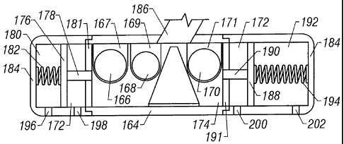
Figure 3 illustrates, schematically, an alternative embodiment of a ball-
dropping mechanism
164 which can be used to drop three different diameter balls 166, 168 and 170
through the ball port
186. The ball port 186 is coupled into the sub 84 illustrated in Figure 1, and
in so doing, the ball-
dropping mechanism 164 substitutes for the two ball, ball-dropping mechanism
64.
The ball-dropping mechanism 164 has an interior chamber 172 through which a
ball carrier
174 can traverse to align the receptacles 167, 169 and 171 with the ball port
186. A first piston 176
having a shaft 178 attached to one end of the ball carrier 174 and passing
through a seal 181, is
adapted to traverse the cylinder 180, the cylinder 180 merely being the end
portion of the chamber
172. A return spring 182 is connected between the piston 176 and the outer
housing 184.
A second piston 188 having a shaft 190 attached to a second end of the ball
carrier 174 and
passing through a seal 191, is adapted to traverse the cylinder 192, which
also is merely the other end
CA 02380286 2001-10-26
WO 01/07748 PCT/US00/11704
of the chamber 172. A return spring 194 is connected between the piston 188
and the outer housing
184, surrounding the chamber 172.
A pair of ports 196 and 198 are provided in the housing 184 on opposite sides
of the piston
176 to allow a conventional pressure source (not illustrated), usually
pneumatic, to drive the piston
5 176 one way or the other. Similarly, a second pair of piston ports 200 and
202 are provided in the
housing 184 on opposite sides of the piston 188 to allow a conventional
pressure source (not
illustrated) to drive the piston 188 one way or the other. For example, if it
is desired to align the ball
168 and the receptacle 169 with the ball port 186, air pressure can be applied
to the ports 200 and
196 while venting the ports 202 and 198 to the atmosphere to complete the
desired alignment and
drop the ball 168 into the ball port 186.
To drop the second largest ball 170, the process is reversed by venting ports
196 and 200 to
the atmosphere while applying air pressure to ports 198 and 202. Until the
ball 170 is dropped, and
while residing in the receptacle 171, the ball 170 in conjunction with a
safety pin 195, described in
detail in Figure 6, limits the movement of the ball carrier 174 so that as
between balls 170 and 166,
only the ball 170 can be aligned to drop into the ball port
186. Once the bal1170 has been dropped, the safety pin no longer limits the
movement of the carrier
174, allowing the largest ball 166 to be aligned and dropped into the ball
port 186.
Referring now to Figure 4, there is illustrated a pneumatic circuit for
controlling the three
ball, ball dropping mechanism illustrated in Figure 3. A conventional source
of air pressure (not
illustrated) is connected to the input line 210 which, in turn, is connected
to inputs 212, 214 and 216
of actuating "A" valves 213, 215 and 217 respectively. The outputs of valves
213, 215 and 217 are
connected to the inputs 220, 222 and 224 of actuating "B" valves 221, 223 and
225 respectively.
CA 02380286 2001-10-26
WO 01/07748 PCT/US00/11704
6
The outputs 228 and 232 of the valves 221 and 225 are tied together and
connected into one input
235 of a two-position pneumatic valve 236. The output 230 of valve 223 is
connected into a second
input 237 of valve 236.
The input 210 is also connected to an input 240 of a pneumatic valve 242. The
output 228
of valve 221 is connected into an input 244, whose output is connected to a
second input 248 of
valve 242. The output 250 of the valve 242 is connected to a second input 246
of switch 244.
In the operation of the pneumatic circuit of Figure 4, used to control the
dropping of the three
balls 166, 168 and 170 in Figure 3, it should be appreciated that the spring-
loaded, push-on
pneumatic valves 213 and 221 control the drop of the smaller ball 166. Neither
the valve 213 nor
the valve 221 will allow the pressurized air to pass through unless the
buttons "A" and "B" are
depressed. The switch 244 allows pressurized air into input 243 and input 246.
The output of the
switch 244 is coupled into the input 248 of pneumatic valve 242.
Upon the simultaneous depression of the "A" and "B" buttons of valves 213 and
221,
pressurized air is found at the input 243 of valve 244, and at the input 248
of valve 242, causing the
valve 242 to open and allowing pressurized air to flow from input 240 to
output 250. This causes
pressurized air to flow into the input 246 of switch 244 and into input 248 on
valve 242, causing
valves 242 to remain open even when the "A" and "B" buttons of valves 213 and
221 are no longer
depressed.
The pressurized air from output 250 of valve 242 is also found at input 251 of
the pneumatic
valve 236, a two-position valve which supplies pressurized air either from
output 253 or output 255,
but not both simultaneously.
CA 02380286 2001-10-26
WO 01/07748 PCT/US00/11704
7
The output 253 of Figure 4 is connected to the port 196 in Figure 3. The
output 255 of Figure
4 is connected to the port 202 of Figure 3.
Thus, the system of Figures 3 and 4 have the feature that in dropping the
three balls, 166, 168
and 170, only the smallest ball 168 can be dropped first. If the "A" and "B"
buttons of valves 215
and 223, and/or the "A" and "B" buttons of valves 217 and 225 are depressed
first, by accident or
otherwise, nothing will happen because the pressurized air is blocked from
passing through the valve
242 and hence, through the valve 236.
However, once the valves 213 and 221 are opened, the pressurized air passes
through valve
236, out through its output 253 to the port 196, moving the ball carrier 174
into alignment with the
ball port 186 to drop the smallest ball 168. Because the valve 242 remains
open, the second and
third balls 170 and 166 can be successively dropped.
As another fail-safe feature, because of the safety pin which protects the
ball carrier 174 from
moving far enough to allow the ball 166 to be dropped, the largest ball 166
cannot be dropped before
the ball 170 is dropped.
To drop the ball 170, the "A" and "B" buttons of valves 214 and 222 are
depressed, causing
the pressurized air to flow from the output 255 of valve 236, and into the
port 202. This causes the
ball carrier 174 to move laterally, aligning the ball 170 with the ball port
186, causing the ball 170
to be dropped.
Because ball 170 is now dropped, the safety pin no longer hinders the movement
of the ball
carrier 174. By depressing "A" and "B" buttons of valves 217 and 225. the
pressurized air from
input 251 is passed out through the output 253 of valve 236, connected to the
port 196, which causes
the ball carrier to move laterally, to align the largest ball 166 with the
ball port 186.
CA 02380286 2001-10-26
WO 01/07748 PCT/US00/11704
8
Thus, Figures 3 and 4 provide a fail-safe, fully automated system to
successively drop these
different sized balls into a tubular string. Preferably, this involves first
the smaller ball, i. e., having
a 1-3/8" diameter, and second, the next larger ball, i.e., having a 1-5/8"
diameter, and third, the
largest ball, i.e., having a 1-7/8" diameter. However, the apparatus of Figure
3 can easily be
modified to change the sequence, for example, to allow either the larger ball
or the next larger ball
to be dropped first, merely by swapping the receptacles 167, 168 and 171, and
the balls 166, 168 and
179 therein respectively, in any order desired.
Referring now to Figure 5, a safety pin 83 is illustrated as being connected
to the end wall
85 of housing 84. The pin 83 is slidably moveable through the sidewall 73 of
the pocket containing
the ball 70, and protrudes slightly into the pocket space.
In the operation of the safety pin 83, the ball carrier can not be moved down
to drop the ball
68 because of the ball 70 pushing against the end of the pin 83. Once the ball
70 has been dropped,
the ball carrier 72 can move along the length of the pin 83 to align the ball
68 with the ball channel
86 to cause the ball 68 to drop into the tubular sub 84.
In a similar, but slightly different mode, the safety pin 195 illustrated in
Figure 6 is connected
to the wall and protrudes slightly through the piston 188.
In the operation of the safety pin 195, the ball carrier 174 is moved down to
align the ba11168
with the ball channel 186. The safety pin 195 extends through the end wall 205
to protrude slightly
into the pocket 171 and against the side of bal1170. This action prevents the
ball carrier from being
moved far enough to drop ball 166. However, by moving the ball carrier to
align the ball 170 with
the ball channel 186, and thus causing the ball 170 to drop, the pin 195 can
protrude further into
pocket 171 and allow ball 166 to be dropped.