Note: Descriptions are shown in the official language in which they were submitted.
CA 02385694 2002-03-19
WO 02/13649 PCT/USO1/23913
SLH)ER-OPERATED FASTENER WITH SPACED NOTCHES AND
ASSOCIATED PRESEALS
FIELD OF THE INVENTION
The present invention generally relates to reclosable plastic bags and, more
particularly, to a slider-operated fastener with spaced notches and associated
preseals.
BACKGROUND OF THE INVENTION
In one method of making reclosable plastic bags, a continuous fastener is
sealed
to a moving web of thermoplastic film. To form individual bags, the web is
folded along
a fold parallel to the direction of web movement, and the folded web is sealed
at bag-
width distances apart along side seals that are generally transverse to the
direction of web
movement. To facilitate opening and closing the fastener, sliders are
preferably applied
to the fastener at bag-width distances apart.
The fastener includes a pair of interlocking profiles and a pair of
fms/flanges
extending downward from the respective profiles. In one technique for
installing sliders
on the fastener, notches are formed in the fastener at bag-width distances
apart. The side
seals, which are formed later in the bag manufacturing process, are aligned
with the
respective notches. To install a slider on the fastener via a respective
notch, the slider is
first positioned within the notch while the web is temporarily stopped, and
then the slider
is threaded onto an end of the fastener in response to relative movement of
the slider and
fastener.
To form a notch, a short segment of the interlocked profiles and an upper
portion
of the fms extending from that segment are cut away from the fastener, leaving
only a
lower portion of the fins bridging opposite sides of the notch. Due to the
removal of
most of the fastener at the notches, the fastener can be difficult to control
during such
downstream operations as slider installation and when tensioned by various
rollers in a
bag making machine. The fastener tends to twist and distort and the fastener
profiles
tend to shift longitudinally relative to each other. In addition, the notches
produce areas
where air or liquid can potentially leak into or out of the bags eventually
formed by the
bag making machine.
CA 02385694 2005-O1-05
2
SiTMMARY OF THE INVENTION
To overcome the aforementioned shortcomings, the present invention provides a
unique slider-operated fastener and method of making the same. The slider-
operated
fastener comprises first and second opposing tracks including respective first
and second
interlocking profiles and respective first and second fins extending downward
from the
respective first and second profiles. The first and second fins are sealed to
each other by
a plurality of spaced preseals. After generating each preseal, a notch is
formed in the
profiles and upper portions of the fins at the generated preseal. To install a
slider onto
the fastener, the slider is initially positioned within the respective notch
and then
threaded onto the fastener in response to relative movement of the slider and
the fastener.
Either before or after the steps of forming each preseal and respective notch
and
installing the respective slider, the fastener is attached to a moving web of
plastic film.
The fastener-carrying web is later folded and sealed to form individual
plastic bags.
According to one aspect of the present invention, there is provided a slider-
operated fastener, comprising a first track including a first profile and a
first fin
extending downward from the first profile, a second track including a second
profile and
a second fin extending downward from the second profile, the second profile
adapted to
interlock with the first profile, the first and second fins being sealed to
each other by a
plurality of longitudinally spaced preseals adjacent to the profiles, and a
plurality of
longitudinally spaced notches periodically interrupting the profiles and
proximate
portions of the fins at the respective preseals, each of the plurality of
longitudinally
spaced notches being configured to receive a slider.
According to a further aspect of the present invention, there is provided a
slider-
operated fastener, comprising first and second opposing tracks including
respective first
and second interlocking profiles and respective first and second fins
extending downward
from the respective first and second profiles, the first and second fins being
sealed to
each other by spaced preseals and having spaced notches formed therein at
least partially
encompassed by the respective preseals such that the preseals assist in
providing a
leakproof barrier to entry into an interior of the fastener between the fins
via the notches,
the notches for receiving a slider.
According to another aspect of the present invention, there is provided a
slider
operated fastener, comprising first and second opposing tracks including
respective first
CA 02385694 2005-O1-05
2a
and second interlocking profiles and respective first and second fins
extending downward
from the respective first and second profiles, a plurality of spaced preseals
sealing the
first and second fins to each other, a plurality of notches interrupting the
profiles and
proximate portions of the fins at the respective preseals, the notches being
at least
partially encompassed by the respective preseals, and a plurality of sliders
for opening
and closing the first and second interlocking profiles, each of the sliders
being threaded
onto the interlocking profiles at a corresponding one of the plurality of
notches.
According to yet another aspect of the present invention, there is provided a
slider-operated fastener, comprising first and second opposing tracks
including respective
first and second interlocking profiles and respective first and second fins
extending
downward from the respective first and second profiles, and the first and
second fins
being sealed to each other by spaced preseals and being notched with in the
respective
preseals to a size to accommodate a slider, the first an second profiles also
being notched
proximate the respective preseals.
According to still another aspect of the present invention, there is provided
a
slider-operated fastener, comprising first and second opposing tracks
including respective
first and second interlocking profiles an respective first and second fins
extending
downward from the respective first and second profiles, and the first and
second fins
being attached to each other at spaced attachment regions an being notched
proximate the
respective attachment regions for receiving a slider, the first and second
profiles also
being notched proximate aid respective attachment regions.
According to a further aspect of the present invention, there is provided a
method
of making a fastener arrangement, comprising providing a fastener including
first and
second opposing tracks, the first and second tracks including respective first
and second
interlocking profiles and respective first and second fins extending downward
from the
respective first and second profiles, sealing the first and second fins to
each other to form
spaced preseals, after sealing the first and second fins to each other at each
of the spaced
preseals, forming a notch within the respective preseal and the first and
second profiles at
the respective preseal, positioning a slider within each of the notches, and
threading the
positioned slider onto the fastener in response to relative movement of the
slider and the
fastener.
According to another aspect of the present invention, there is provided a
method
of making a fastener arrangement, comprising providing a fastener including
first and
CA 02385694 2005-O1-05
2b
second opposing tracks, the first and second tracks including respective first
and second
interlocking profiles and respective first and second fins extending downward
from the
respective first and second profiles, sealing the first and second fins to
each other at
spaced preseals, after sealing the first and second fins to each other at each
of the spaced
preseals, forming a notch in the fins and the profiles at the respective
preseal, inserting a
slider onto the fastener through the notch, attaching the fastener to a moving
web of
plastic film, and folding the web along a fold parallel to the direction of
web movement.
The preseals are advantageous in that they allow the fastener to be controlled
during such downstream operations as notch formation and slider installation
and when
~e fastener is tensioned by various rollers in the bag making machine. The
preseals keep
the interlocked profiles together and prevent them from moving longitudinally
relative to
each other. In addition, the preseals generally encompass the respective
notches to assist
in providing a leakproof barner to entry into an interior of the fastener
between the fins
via the notches. This leakproof barner is effective in the ultimately formed
plastic bags.
BRIEF DESCRIPTION OF THE DRAWINGS
Other objects and advantages of the invention will become apparent upon
reading
the following detailed description and upon reference to the drawings in
which:
FIG. 1 depicts a method of making a slider-operated fastener;
FIG. 2 depicts a method of forming, filling, and sealing reclosable plastic
bags
employing the slider-operated fastener;
FIG. 3 depicts a finished bag produced by the form-fill-seal method after the
bag's header has been partially removed by an end user;
FIG. 4 is an enlarged view of a U-shaped preseal according to a first
embodiment;
FIG. 5 is an enlarged view of a solid preseal according to a second
embodiment;
CA 02385694 2005-O1-05
3
FIG. 6 is an enlarged view of a bracketed preseal according to a third
embodiment;
FIG. 7 is an enlarged view of a notch in the U-shaped or solid preseals of
FIGS. 4
and 5; and
s FIG. 8 is an enlarged view of a notch in the bracketed preseal of FIG. 6.
While the invention is susceptible to various modifications and alternative
forms,
a specific embodiment thereof has been shown by way of example in the drawings
and
will herein be described in detail. It should be understood, however, that it
is not
intended to limit the invention to the particular forms disclosed, but on the
contrary, the
io intention is to cover all modifications, equivalents, and alternatives
falling within the
spirit and scope of the invention as defined by the appended claims.
DESCRIPTION OF ILLUSTRATIVE EMBODIMENTS
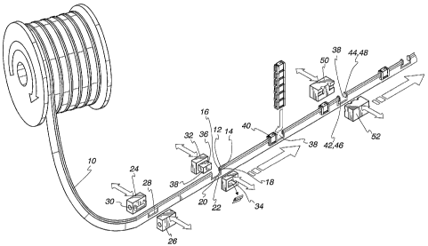
Turning to the drawings, FIG. 1 depicts a method of making a slider-operated
is fastener for use in reclosable plastic bags. In the method, there is
provided a continuous
fastener I O including first and second opposing tracks 12 and 14. The tracks
I2 and 14
include respective first and second interlocking profiles 16 and 18 and
respective first
and second fins 20 and 22 extending downward from the respective profiles 16
and 18.
The profile 16 preferably includes a rib, and the profile 18 preferably
includes a groove
Zo for receiving the rib. Further details concerning the construction of the
profiles 16 and
18 may be obtained from U.S. Patent No. 5,007,143 to Herrington. The fastener
10 may
be unwound from a spool or the like.
The fastener 10 is conveyed by rollers and the like (not shown) to a preseal
is station. The preseal station includes a pair of reciprocating seal bars 24
and 26. Either
both of the seal bars 24 and 26 move back and forth between open and closed
positions,
or one of the seal bars is stationary while the other seal bar moves back and
forth. At
least the seal bar 24 is heated. The other bar 26 may be heated as well, or
may simply
serve as a backing against which the heated seal bar 24 applies pressure when
the seal
so bars 24 and 26 are brought together. The temperature, pressure, and dwell
time of the
seal bars 24 and 26 are properly adjusted to allow the seal bars 24 and 26 to
impart a
preseal 28. While the fastener 10 is temporarily stopped at the preseal
station, the fins 20
CA 02385694 2002-03-19
WO 02/13649 PCT/USO1/23913
4
and 22 are sealed to each other along the preseal 28. The preseal 28
preferably does not
extend into the profiles 16 and 18 due to the technique for installing sliders
on the
fastener 10 later in the manufacturing process.
FIGS. 4-6 illustrate different configurations of the preseal. The preseal 28
in FIG.
s 4 is generally U-shaped and includes a pair of opposing sides 28a, 28b and a
bottom 28c
bridging the opposing sides. The opposing sides 28a, 28b are generally located
along an
upper portion of the fins 20 and 22 and extend downward from the interlocked
profiles
16 and 18. The bottom 28c extends between the lower ends of the sides 28a,
28b. The
seal bar 24 has a U-shaped projection 30 corresponding to the shape of the
preseal 28.
io The preseal 28' in FIG. 5 is solid such that the rectangular area between
the opposing
vertical sides of the preseal is sealed. The bracketed preseal 28" in FIG. 6
is similar to
the U-shaped preseal 28 in FIG. 4 except that the bottom of the bracketed
preseal 28" is
interrupted by a gap. The gap has a width W less than or equal to the width X
of a side
seal later formed in alignment with the preseal 28". An advantage of the
bracketed
is preseal 28" is that it minimizes the heat imparted to the lower portions of
the fms 20 and
22, thereby minimizing stretching and subsequent shrinkage and wrinkles in the
lower fin
portions.
After forming the preseal 28, the fastener 10 is conveyed to a notching
station.
The notching station includes a pair of reciprocating cutters 32 and 34.
Either both of the
ao cutters 32 and 34 move back and forth between open and closed positions, or
one of the
cutters is stationary while the other cutter moves back and forth. The cutter
32 forms a
rectangular projection, while the cutter 34 forms a rectangular hole for
receiving the
projection. The fastener 10 is temporarily stopped at the notching station
with the
preseal 28 aligned between the separated cutters 32 and 34. While the fastener
10 is
zs stopped, the cutters 32 and 34 are brought together such that the
rectangular projection of
the cutter 32 punches a rectangular section 36 through the rectangular hole of
the cutter
34, thereby leaving a U-shaped notch 38 in the fastener 10.
The preseal 28 generally encompasses the notch 38 and defines a periphery
thereof such that the preseal provides a leakproof barrier to entry into an
interior of the
so fastener 10 between the Ens 20 and 22 via the notch 38. As discussed below,
the
leakproof barrier effectively prevents leaks in the reclosable plastic bags
ultimately
formed by the manufacturing process. FIG. 7 illustrates the notch 38 in either
the U-
CA 02385694 2005-O1-05
S
shaped preseal 28 of FIG. 4 or the solid preseal 28' of FIG. 5. FIG. 8
illustrates the notch
in the bracketed preseal 28" of FIG. 6. The bracketed preseal 28" is still
effective to
create the aforementioned leakproof barrier because the brackets are sized to
overlap the
side seal to be formed-later in the manufacturing process.
After forming the notch 38, the fastener 10 is conveyed to a slider insertion
station. While the fastener 10 is temporarily stopped at the slider insertion
station, a
slider 40 from a source of multiple sliders is positioned within the notch 38.
The slider
40 is then threaded onto the fastener 10 in response to relative movement of
the slider 40
and the fastener 10.
io After installing the slider 40 onto the fastener 10, the fastener 10 is
conveyed to
an end stop applicator. The end stop applicator applies end stops 42 and 44 to
the
respective fastener ends 46 and 48 on opposite sides of the notch 38. In the
plastic bags
ultimately formed by the manufacturing process, the end stap 42 will be
located at the
fastener end 46 of one bag, while the end stop 44 will be located at the
fastener end 48 of
is the adjacent bag. The end stops perform three primary functions: (1)
preventing the
slider 40 from going past the ends of the fastener, (2) holding the profiles
together to
resist stresses applied to the profiles during normal use of the plastic bag,
and (3)
minimizing leakage from inside the plastic bag out through the fastener ends.
In one embodiment, the end stop applicator includes a pair of chilled,
Zo reciprocating molds 50 and 52. Either both of the molds SO and 52 move back
and forth
between open and closed positions, or one of the molds is stationary while the
other mold
moves back and forth. While the fastener 10 is temporarily stopped, the molds
50 and 52
close around the fastener ends 46 and 48. A predetermined amount of flowable
plastic
material is then forced around and between the profiles 16 and 18 at the
fastener ends 46
Zs and 48 by a conventional back pressure device (not shown) coupled to the
supply tube.
The molds 50 and 52 form channels for receiving the plastic material and
guiding it to
the fastener ends 46 and 48.
Instead of applying injection-molded end stops, other types of end stops may
be
applied to the fastener ends 46 and 48, including those disclosed in U.S.
Patent Nos.
so 5,924,173, 5,833,791, 5,482,375, 5,448,807, 5,442,837, 5,405,478,
5,161,286, 5,131,121,
5,088,971, and 5,067,208. In the U.S. Patent No. 5,067,208, for example,,
each end stop is in the form of a fairly rigid
CA 02385694 2002-03-19
WO 02/13649 PCT/USO1/23913
6
strap/clip that wraps over the top of the fastener. One end of the strap is
provided with a
rivet-like member that penetrates through the fastener fins and into a
cooperating opening
at the other end of the strap.
While the fastener 10 is temporarily stopped in the method depicted in FIG. l,
the
s various stations simultaneously perform their respective functions on
different parts of
the continuous fastener 10 spaced approximately at bag-width distances apart.
Therefore,
as the preseal station forms a new preseal 28, (1) the notching station forms
a new notch
38 within a previously formed preseal, (2) the slider insertion station
installs a slider 40
via a previously formed notch, and (3) the end stop applicator applies new end
stops 42
io and 44 proximate a previously installed slider. After each of the stations
has completed
its respective function on the stopped fastener 10, movement of the fastener
10 is
resumed. The fastener 10 is moved for approximately a bag-width distance so
that the
next station can perform its respective function. The preseals 28 are
advantageous in that
they allow the fastener 10 to be controlled during such downstream operations
as notch
is formation, slider installation, and end stop installation and when the
fastener 10 is
tensioned by various rollers in the bag making machine. The preseals 28 keep
the
interlocked profiles 16 and 18 together and prevent them from moving
longitudinally
relative to each other.
After applying the end stops 42 and 44, the fastener 10 is preferably applied
to a
zo moving web of plastic film that is then formed into individual plastic
bags.
Alternatively, the fastener 10 may be conveyed to a storage medium, such as a
spool, and
placed in an intermediate storage facility, and then applied to the moving web
at a later
time.
FIG. 2 depicts a method of forming, filling, and sealing reclosable plastic
bags
as employing the slider-operated fastener 10. The fin 20 of the fastener 10 is
"tacked" or
lightly sealed to a moving web 50 of plastic film unwound from a film roll 52.
To tack
the fastener fin 20 to the moving web 50, there is 'provided a pair of
reciprocating seal
bars 54 and 56. Either both of the seal bars 54 and 56 move back and forth
between open
and closed positions, or one of the seal bars is stationary while the other
seal bar moves
so back and forth. Both the fastener 10 and the web 50 are temporarily stopped
while the
seal bars are brought together to tack the fastener 10 to the web 50. Of
course, if the
fastener 10 produced by the method in FIG. 1 is conveyed directly to the web
50, as
CA 02385694 2002-03-19
WO 02/13649 PCT/USO1/23913
7
opposed to an intermediate storage facility, the stoppage of the fastener 10
and web 50
for tacking can be made to coincide with the stoppage of the fastener 10 in
FIG. 1 for
forming the preseal and notch and installing the slider and end stops. In an
alternative
embodiment, the seal bars 54 and 56 are replaced with a static heat sealing
mechanism
s such as a hot air blower that blows heated air onto the fastener 10. The
tacked fastener
is carried with the moving web 50 without shifting relative thereto.
After tacking the fastener 10 to the web 50, the fastener-carrying web SO is
conveyed to a folding station. At the folding station, the web 50 is folded in
half with the
fastener 10 inside the web 50 and proximate the fold 51. To fold the web 50,
the web 50
io is conveyed over a horizontal roller 58, under a triangular folding board
60, and then
between a pair of closely spaced vertical rollers 62. The folded web 50
includes a pair of
overlapping panels 64 and 66 joined along the fold 51.
After folding the web 50, the fastener fins 20 and 22 are permanently sealed
to
the respective web panels 66 and 64 by respective seal bars 68 and 70. The
seal bars 68
is and 70 are sufficiently wide that they generate the fm seals across the
entire width of a
bag produced by the method in FIG. 2. Either both of the seal bars 68 and 70
move back
and forth between open and closed positions, or one of the seal bars is
stationary while
the other seal bar moves back and forth. The fastener-carrying web 50 is
temporarily
stopped while the seal bars are brought together to seal the fastener 10 to
the web 50.
ao Both of the seal bars 68 and 70 are preferably heated. The temperature,
pressure, and
dwell time of the seal bars 68 and 70 are properly adjusted to allow the seal
bars 68 and
70 to generate the permanent fm seals. W an alternative embodiment, the seal
bars 68
and 70 are replaced with a static heat sealing mechanism such as a pair of hot
air blowers
that blow heated air onto the respective fastener fins.
as After sealing the fins 20 and 22 to the respective web panels 66 and 64,
the web
panels 64 and 66 are sealed to each other along a side seal 72 by a pair of
reciprocating
seal bars 74 and 76. The side seal 72 is transverse to a direction of movement
of the
folded web 50 and is aligned with a center of the notch 38 (and preseal 28).
Also, the
side seal 72 extends from the folded bottom 51 to an open top 53 of the folded
web 50.
3o Either both of the seal bars 74 and 76 move back and forth between open and
closed
positions, or one of the seal bars is stationary while the other seal bar
moves back and
forth. The folded web 50 is temporarily stopped while the seal bars are
brought together
CA 02385694 2002-03-19
WO 02/13649 PCT/USO1/23913
8
to seal the web panels 64 and 66 to each other. At least the seal bar 74 is
heated. The
other bar 76 may be heated as well, or may simply serve as a backing against
which the
heated seal bar 74 applies pressure when the seal bars 74 and 76 are brought
together.
The temperature, pressure, and dwell time of the seal bars 74 and 76 are
properly
s adjusted to allow the seal bars 74 and 76 to generate the side seal 72.
After generating the side seal 72, the folded web 50 is conveyed to a cutter
78 for
separating the folded web 50 into individual plastic bags. While the folded
web 50 is
temporarily stopped, the cutter 78 cuts the folded web 50 along a center of
the side seal
72 to produce the individual plastic bag 80. The plastic bag 80 is opened with
an
io opening device 79 and filled with a product through its open top 53 at a
filling station 82.
Finally, the open top 53 is sealed by a heat sealing mechanism 84. The end
result is a
filled and sealed bag 80 ready for shipment to a customer such as a grocery
store or
convenience store.
While the web 50 is temporarily stopped in the method depicted in FIG. 2, the
is various stations simultaneously perform their respective functions on
different parts of
the continuous web 50. For example, as the fastener 10 is tacked to the web 50
by the
seal bars 54 and 56, (1) the fastener fins 20 and 22 of a previously tacked
section of the
fastener 10 can be permanently sealed to the respective web panels 64 and 66
by
respective seal bars 68 and 70, (2) the web panels 64 and 66 carrying
previously sealed
zo fastener fin sections can be sealed to each other along a side seal 72 by
the seal bars 74
and 76, (3) the folded web 50 can be cut along a previously generated side
seal, (4) the
cut bag is opened, (5) the opened bag is positioned under a filling device
that fills the
bag, and (6) the filled bag is sealed closed. After each of the stations has
completed its
respective function on the stopped web 50, movement of the web 50 is resumed.
as The finished bag 80, with its header 82 partially removed by an end user,
is
illustrated in FIG. 3. After the header 82 is fully removed, it can be seen
that each
preseal 28 intersects both the adjacent side seal 72 and the fastener profiles
16 and 18.
Therefore, the preseal 28 provides a leakproof barrier between an interior and
an exterior
of the bag 80. When the profiles 16 and 18 are interlocked but the header 82
has been
3o removed, this leakproof barner minimizes food spoilage and leakage of any
food juices
from inside the bag.
CA 02385694 2002-03-19
WO 02/13649 PCT/USO1/23913
9
While the present invention has been described with reference to one or more
particular embodiments, those skilled in the art will recognize that many
changes may be
made thereto without departing from the spirit and scope of the present
invention. For
example, the equipment used in the fastener and bag manufacturing processes
may be
s modified so that the processes are entirely continuous with no temporary
stoppages in the
movement of the fastener or bag making web. Also, the fastener 10 may be
attached to
the web 50 prior to forming the preseal 2~ and notch 3~, installing the slider
40, and
applying the end stops 42 and 44. To allow the fastener 10 to be accessed for
such
operations, however, the operations are preferably performed prior to folding
the web 50
io and enveloping the fastener 10 therein. Each of these embodiments and
obvious
variations thereof is contemplated as falling within the spirit and scope of
the claimed
invention, which is set forth in the following claims.
is