Language selection

Search

Patent 2386708 Summary

Third-party information liability

Some of the information on this Web page has been provided by external sources. The Government of Canada is not responsible for the accuracy, reliability or currency of the information supplied by external sources. Users wishing to rely upon this information should consult directly with the source of the information. Content provided by external sources is not subject to official languages, privacy and accessibility requirements.

Claims and Abstract availability

Any discrepancies in the text and image of the Claims and Abstract are due to differing posting times. Text of the Claims and Abstract are posted:

  • At the time the application is open to public inspection;
  • At the time of issue of the patent (grant).
(12) Patent: (11) CA 2386708
(54) English Title: A PUMP VALVE
(54) French Title: SOUPAPE DE POMPE
Status: Expired
Bibliographic Data
(51) International Patent Classification (IPC):
  • F16K 15/03 (2006.01)
  • F16K 1/18 (2006.01)
  • F16K 15/02 (2006.01)
(72) Inventors :
  • SANTA, JOSEPH LUIZ (Australia)
(73) Owners :
  • JOE SANTA & ASSOCIATES PTY. LIMITED (Australia)
(71) Applicants :
  • JOE SANTA & ASSOCIATES PTY. LIMITED (Australia)
(74) Agent: ROBIC
(74) Associate agent:
(45) Issued: 2009-07-14
(22) Filed Date: 2002-05-17
(41) Open to Public Inspection: 2002-11-30
Examination requested: 2006-12-14
Availability of licence: N/A
(25) Language of filing: English

Patent Cooperation Treaty (PCT): No

(30) Application Priority Data:
Application No. Country/Territory Date
PR5343 Australia 2001-05-30

Abstracts

English Abstract

A one-way fluid valve member (10) to be mounted on a valve (12) body having a valve opening (18) surrounded by a valve seat (16). The valve member (10) includes,: a valve closure part (14) to be movably mounted on the body (12) for movement relative thereto between a first position engaging the seat (16) to prevent movement of fluid through the opening (18) in a predetermined direction, and a second position spaced from the seat (16) to allow fluid to pass through the opening (18) in a direction opposite the predetermined direction; and wherein the valve closure part (14) has a convex surface to engage the seat (16) so as to project into the opening (18).


French Abstract

Élément de soupape de fluide unidirectionnelle (10) destiné à être monté sur un corps de soupape (12) ayant une ouverture (18) entourée d'un siège de soupape (16). L'élément de soupape (10) comprend un élément de fermeture de soupape (14) destiné à être fixé de manière détachable sur le corps (12) afin de lui permettre de bouger par rapport à celui-ci entre une première position de prise avec le siège (16), qui empêche le fluide de passer à travers l'ouverture (18) dans une direction, et une deuxième position à distance du siège (16), qui permet au fluide de passer à travers l'ouverture (18) dans une direction opposée à la direction prédéterminée. La partie de fermeture de la soupape (14) comporte une surface convexe servant à entrer dans le siège (16) de manière à s'avancer en saillie dans l'ouverture (18).

Claims

Note: Claims are shown in the official language in which they were submitted.


4
WHAT IS CLAIMED IS:

1. A one-way fluid valve member to be mounted on a valve body
having a valve opening surrounded by a valve seat located in a plane, said
valve
member including:
a valve closure part to be movably mounted on said valve body for
movement relative to said valve body by flow of said fluid in predetermined
and
opposite directions between a first position engaging said valve seat to
prevent
said flow of said fluid through said opening in said predetermined direction,
and
a second position spaced from said valve seat to allow fluid to pass through
said
opening in said opposite direction; and
a hinge member to mount said valve closure part on said body and
including a pivot portion, the pivot portion being spaced from said valve
closure
part in said opposite direction, and at least one arm attaching said valve
closure
part to said pivot portion, said hinge member and valve closure part defining
a
channel for flow of said fluid,
wherein said valve closure part maintains its configuration during said
movement, said movement being at least partly provided by resilient
deformation of said pivot portion, and
a portion of said pivot portion is spaced in said opposite direction over
said arm for preventing said second position of said valve closure part from
projecting in said opposite direction sufficiently that flow of said fluid in
said
predetermined direction will not move said valve closure part to said first
position.

2. A one-way fluid valve member according to claim 1, wherein said
valve closure part includes a pair of longitudinally extending arms attaching
said
valve closure part to said pivot.

3. A one-way fluid valve member according to claim 2, wherein said
arms are flexible.


5
4. A one-way fluid valve member according to claim 1, wherein said
valve member is of a unitary construction.

5. A one-way fluid valve member according to claim 2, wherein said
valve member is of a unitary construction.

6. A one-way fluid valve member according to claim 3, wherein said
valve member is of a unitary construction.

7. A one-way fluid valve member according to claim 1, wherein said
valve closure part has a convex top and bottom surface, said bottom surface to
engage said seat so as to project into said opening.

Description

Note: Descriptions are shown in the official language in which they were submitted.


CA 02386708 2008-07-31
1

A PUMP VALVE
Field of the Invention

The present invention relates to pumps and more par-ticularly but not
exclusively
to a flap valve for a pump.

Background of the Invention

Common valve assemblies (such as that disclosed in the Applicant's
Intemational Application PCT/AU93/00686 (W093118305)) are generally made in
three
pieces and include a first hinge.d plate, a valve, a further hinged plate and
nuts cooperating
with screw inserts to form a valve assembly. Under the influence of pressure,
th.e hinge
valve (or flap) pivots to open or close the valve opening. In this type of
"three-piece"
arrangement it has been found that problems arise when solids are caught under
the hinge
plate (flap). The obstructions have been found to prevent complete closure,
resulting in a
loss of vacuum causing the pump to stop.
It is therefore desirable to provide a one-piece valve assembly which
overcomes
these problems by having a lugher hinge point and a more penetrating closure
mechanism. This type of arrangement would also be effected less by the build
up of
solids due to its better clearance.

Object of the Invention

It is the object of the present invention to overcome or substantially
ameliorate at
least one of the above disadvantages or to provide a useful alternative.

Summary of the Inventiori

There is firstly disclosed herein a one-way fluid valve member to be
mounted on a valve body having a valve opening surrounded by a valve seat
located in a plane, said valve member including:
a valve closure part to be movably mounted on said valve body for
movement, relative to said valve body by flow of said fluid in predetermined
and
opposite directions between a first position engaging said valve seat to
prevent
said flow of said fluid through said opening in said predetermined direction,
and


CA 02386708 2008-07-31

2
a second position spaced from said valve seat to allow fluid to pass through
said
opening in said opposite direction; and
a hinge member to mount said valve closure part on said body and
including a pivot portion, the pivot portion being spaced from said valve
closure
part in said opposite direction, and at least one arm attaching said valve
closure
part to said pivot portion, said hinge member and valveclosure part defining a
channel for flow of said fluid,
wherein said valve closure part maintains its configuration during said
movement, said. movement being at least partly provided by resilient
deformation of said pivot portion, and
a portion of said pivot portion is spaced in said opposite direction over
said arm for preventing said second position of said valve closure part from
projecting in said opposite direction sufficiently that flow of said fluid in
said
predetermined direction will not move said valve closure part to said first
position.

There is further disclosed herein a one-way fluid valve member to be moi.inted
on a valve body having a valve opening surrounded by a valve seat, said valve
meinber
including:
a valve closure part to be movably mounted on said body for movement relative
thereto between a flrst position engaging said seat to prevent movement of
fluid through
said opening in a predetermined direction, and a second position spaced from
the seat to
allow fluid to pass tluougli said opening in a direction opposite said
predetermined
direction; .
a hinge member to mount said valve part on said body, said hinge member being
resiliently deformed to provide for said movement; and wherein
said valve closure part maintains its configuration during movenient as said
hinge resiliently deforms.
Preferably, saici valve seat is located in a plane, and said valve member is
coimected to said body by a pivot spaced from said plane opposite said
predetermined
direction.
Preferably, said valve member is of a unitary constniction.


CA 02386708 2008-07-31

2a
Preferably, said valve part includes a pair of longitudinally extending arms
coiuiected to said pivot.
Preferably, said arms are flexible.
Preferably, said space defines a channel for fluid flow.

Preferably, said valve closure part has a convex top and bottom surface,
said bottom surface to engage said seat so as to project into said opening.

Brief Description of the Drawings

A preferred form of the present invention will now be described by way of
example only with reference to the accompanying drawings wherein:
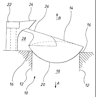
Figure I is schematic side view of a valve member in accordance with an
embodiment of the invention;
Figure 2 is a bottom view of the valve of Figure 1;
Figure 3 is a top view of the valve of Figure 1;
Figure 4 is a front view of the valve of Figure 1; and;
Figure 5 is a rear view of the valve of Figure 1.

Detailed Description of the Preferred Embodiments

In Figures I to 5 of the accompanying drawulgs, there is schematically
depicted
a one-,vay fluid valve member 10 to be mounted on a valve body 12. Valve body
12 is
- ------ ------ /.


CA 02386708 2002-08-28
-3-
part of a pump system which would normally include such features as a number
of punip
cliambers being interconnected to allo-,v fluid flow between a number of
inlets and outlets.
The valve member 10 is made of a unitar), construction and preferably out of
rubber or
similar type products. Valve mernber 10 includes a valve closure part 14
movably
s mounted on the body 12 for movement relative thereto between a-first
position engaging a
valve seat 16 to prevent niovement of fluid through a valve opening 18 in a
predetermined
direction (Arrow A) and a second position spaced from the seat 16 to allow
fluid to pass
through the opening in a direction opposite the predetermined direction (Arrow
B). The
valve closure part 14 has a convex surface 20 which is adapted to engage the
seat 16 and
project into the opening 18 as best shown in Figure 1.
The valve member 10 can further include a hinge member 22 mounted on the
body 12. 'T1ie hinge member projects away from the plane of the valve seat 16
opposite
the predetermined direction (Arrow B). The hinge member 22 includes a
resiliently
deformable hinge pivot portion 24 which is connected to the valve closure part
14 by a
is pair of longitudinal extending arms 26. In use, the valve part 14 maintains
its
configuration during movement whilst the hinge portion 24 resiliently deforms.
In one
preferred einbodiment, the arms 26 could also be deforrnable.
As best seen in Figure 1, when the hinge meinber 22 is displaced away from the
plane of tlie seat 16 (that is, in the direction of Arrow B) and the valve
closure part 14
(being coruiected to the hinge pivot portion 24) is in contact with the seat
16, a channe128
is formed which provides an avenue for fluid to flow without interfering or
preventing the
closure of valve closure part 14 with. the seat 16. 'I'his results in the
vacuum created
within the purnp system being maintained and stops any interruption to
pumping.
Further, due to the convex surface 20 of the valve part 14, better vacuum
closure can be
obtained further increasing the efficiency of the pump.
Although the invention has been described witlt reference to specific
examples, it
will be appreciated by those skilled in the art that the invention may be
embodied in many
other forms.

Representative Drawing
A single figure which represents the drawing illustrating the invention.
Administrative Status

For a clearer understanding of the status of the application/patent presented on this page, the site Disclaimer , as well as the definitions for Patent , Administrative Status , Maintenance Fee  and Payment History  should be consulted.

Administrative Status

Title Date
Forecasted Issue Date 2009-07-14
(22) Filed 2002-05-17
(41) Open to Public Inspection 2002-11-30
Examination Requested 2006-12-14
(45) Issued 2009-07-14
Expired 2022-05-17

Abandonment History

There is no abandonment history.

Payment History

Fee Type Anniversary Year Due Date Amount Paid Paid Date
Application Fee $300.00 2002-05-17
Registration of a document - section 124 $100.00 2002-07-29
Maintenance Fee - Application - New Act 2 2004-05-17 $100.00 2004-04-22
Maintenance Fee - Application - New Act 3 2005-05-17 $100.00 2005-04-22
Maintenance Fee - Application - New Act 4 2006-05-17 $100.00 2006-04-20
Request for Examination $800.00 2006-12-14
Maintenance Fee - Application - New Act 5 2007-05-17 $200.00 2007-04-18
Maintenance Fee - Application - New Act 6 2008-05-19 $200.00 2008-04-16
Maintenance Fee - Application - New Act 7 2009-05-18 $200.00 2009-04-20
Final Fee $300.00 2009-05-01
Maintenance Fee - Patent - New Act 8 2010-05-17 $200.00 2010-04-14
Maintenance Fee - Patent - New Act 9 2011-05-17 $200.00 2011-04-13
Maintenance Fee - Patent - New Act 10 2012-05-17 $250.00 2012-04-11
Maintenance Fee - Patent - New Act 11 2013-05-17 $250.00 2013-04-10
Maintenance Fee - Patent - New Act 12 2014-05-20 $250.00 2014-04-09
Maintenance Fee - Patent - New Act 13 2015-05-19 $250.00 2015-04-22
Maintenance Fee - Patent - New Act 14 2016-05-17 $250.00 2016-04-27
Maintenance Fee - Patent - New Act 15 2017-05-17 $450.00 2017-04-26
Maintenance Fee - Patent - New Act 16 2018-05-17 $450.00 2018-04-26
Maintenance Fee - Patent - New Act 17 2019-05-17 $450.00 2019-04-24
Maintenance Fee - Patent - New Act 18 2020-05-18 $450.00 2020-04-23
Maintenance Fee - Patent - New Act 19 2021-05-17 $459.00 2021-04-21
Owners on Record

Note: Records showing the ownership history in alphabetical order.

Current Owners on Record
JOE SANTA & ASSOCIATES PTY. LIMITED
Past Owners on Record
SANTA, JOSEPH LUIZ
Past Owners that do not appear in the "Owners on Record" listing will appear in other documentation within the application.
Documents

To view selected files, please enter reCAPTCHA code :


To view images, click a link in the Document Description column. To download the documents, select one or more checkboxes in the first column and then click the "Download Selected in PDF format (Zip Archive)" or the "Download Selected as Single PDF" button.

List of published and non-published patent-specific documents on the CPD .

If you have any difficulty accessing content, you can call the Client Service Centre at 1-866-997-1936 or send them an e-mail at CIPO Client Service Centre.


Document
Description 
Date
(yyyy-mm-dd) 
Number of pages   Size of Image (KB) 
Cover Page 2002-11-15 1 33
Abstract 2002-05-17 1 18
Representative Drawing 2002-10-01 1 6
Abstract 2002-08-28 1 19
Description 2002-08-28 3 164
Claims 2002-08-28 2 62
Drawings 2002-08-28 5 53
Description 2002-05-17 3 145
Claims 2002-05-17 2 56
Drawings 2002-05-17 5 48
Claims 2008-07-31 2 54
Description 2008-07-31 4 174
Representative Drawing 2009-06-16 1 8
Cover Page 2009-06-16 2 38
Correspondence 2002-06-27 1 28
Assignment 2002-05-17 3 80
Assignment 2002-07-29 2 66
Correspondence 2002-08-28 13 351
Prosecution-Amendment 2008-07-31 9 266
Prosecution-Amendment 2006-12-14 1 43
Prosecution-Amendment 2008-06-17 3 92
Correspondence 2009-05-01 2 54
Correspondence 2010-08-10 1 47