Note: Descriptions are shown in the official language in which they were submitted.
CA 02387065 2009-09-30
ELECTRO MECHANICAL WEBBED PRE-TENSIONING
WHEELCHAIR SECUREMENT SYSTEM
FIELD OF THE INVENTION
This invention relates to devices for securing a wheelchair to a vehicle. In
particular, the
invention includes a system utilizing stowable webbed belts and utilizing a
power system for
providing tension on said belts.
BACKGROUND
In recent years, it has become a commonplace to provide wheelchair users with
accommodations in mass transit vehicles, such as buses, trains or planes. Such
accommodations
typically allow these persons to ride in the vehicle while remaining in the
wheelchair. It is desirable,
under these circumstances, to secure the occupant and the wheelchair to the
vehicle for the safety of
the user of the wheelchair, as well as the safety of other occupants of the
vehicle.
While numerous methodologies have been developed for securing wheelchairs to
the
interior of vehicles, many of the methods and devices developed for such
securement create
inconveniences to both the wheelchair passenger and the operator of the
vehicle. Because the
wheelchair-using passenger is frequently restricted in body movement, it is
desirable to provide
wheelchair securement systems which are easily reached and manipulated by the
passenger or the
alternative, if such securement systems are not manipulatible solely by the
passenger, it is desirable
to have them easily operable by the vehicle operator or an operator's
assistant. It is also desirable
to provide wheelchair securement systems which are easily repositioned within
the vehicle to permit
the space sometimes used by a wheelchair-using passenger to be readily
converted for use by
persons not so handicapped. For this reason, a wide variety of methodologies
and devices have
been developed in the form of stowable restraints for wheelchairs and
wheelchair-using passengers.
Preferably, such restraints should be positioned in the immediate vicinity of
the area where a
wheelchair will be secured. In known systems using a plurality of belts and
anchors, however,
(belts and anchors which are stowed remotely, for example, in a storage
locker), such belts and
anchors frequently become lost, damaged or soiled when not in use.
Additionally, this type of
restraint almost always requires installation in the vehicle and attachment to
the wheelchair by
1
CA 02387065 2009-09-30
someone other than the wheelchair occupant.
It is also known to provide wheelchair restraint systems which are secured to
the vehicle
and articulate between a stowed and an extended position. This type of
technology is found in U.S.
Patent No. 5,888,038, issued to Ditch et al.; U.S. Patent No. 6,113,325,
issued to Craft.
Even these systems, however, have an important drawback in that it is
difficult to provide the
necessary securement and tension to four discrete points on the wheelchair, in
the fashion in which
the anchoring apparatus for the wheelchair is usually attached to the vehicle,
without the assistance
of a person other than the wheelchair occupant. Existing systems are also
awkward to use and
store.
There is a need, therefore, for a wheelchair tie-down system which is easily
attached to the
wheelchair by the vehicle operator or the wheelchair occupant alone, which is
similarly easy to
tension, and which is readily stowable within the vehicle, eliminating the
presence of any obstacles to
other passengers when the system is not in use.
SUMMARY OF THE INVENTION
In accordance with the invention, a simple-to-use, easily installed tie-down
system for
wheelchairs is provided. The system is installed in public transportation
vehicles in such a fashion as
to present no obstacle to the traveling public when the system is not in use,
but yet is readily
available for operation when needed by a wheelchair-using passenger. The
system allows the same
space in a vehicle to be used, alternatively, by wheelchair using passengers
and by ambulatory
passengers. In one embodiment, the components of the tie-down system are
located in an area of
the bus which may also be occupied by foldable chairs usable by ambulatory
passengers.
Preferably, these chairs may be readily moved away from the area to be
occupied by a wheelchair-
using passenger, and just as easily repositioned for conventional use as
desired.
The system comprises a front tensioning assembly and one or more rear
anchoring
assemblies located in proximity to a wheelchair station. The tensioning and
anchoring assemblies
are mounted to the floor and walls of the vehicle in such a fashion as to
provide the necessary
security to restrain the wheelchair from movement during normal transit and in
the event of a
collision involving the vehicle. The tensioning elements of the system are
provided with locking
means, power-driven tensioning means as well as feedback means to impart an
appropriate amount
2
CA 02387065 2009-09-30
of tension to the tensioning elements automatically. Manual tensioning means
may also be provided.
In use by a wheelchair occupant, the system includes a front tensioning
assembly having a
cooperating pair of webbed belts which are provided with hooks to engage the
front framework of
a wheelchair. The belts are arranged in relationship to a front housing and
front guide in such a
fashion as to provide laterally spaced positions for the hooks and belts,
thereby insuring that both
the right front and left front portions of a wheelchair will be suitably
engaged to restrict both
longitudinal and lateral movement of the front of the wheelchair in relation
to the vehicle. The front
tensioning assembly also features a covered enclosure portion in which the
inboard front belt and
hook can be stowed when the tensioning system is not in use. This enclosure is
designed with an
extremely low profile, thereby presenting no obstacle to other passengers when
the system is not in
use by a wheelchair-using passenger. In one embodiment, one or more rear
anchor assemblies are
provided behind the wheelchair station in the vehicle, aft of the front
tensioning assembly in such a
fashion as to permit one or more hooks and belts from rear anchor assemblies
to engage one or more
portions of the rear of a wheelchair. Preferably, there are two cooperating
rear anchor assemblies,
one located near the inboard part of the wheelchair station and one located
near the outboard part of
the wheelchair station. These rear anchoring assemblies provide securement of
the wheelchair from
forward movement as well as from lateral movement.
In operation, the front tensioning belts and rear anchoring belts and their
associated hooks are
affixed to the four corner areas of the wheelchair and placed under tension
securing the
wheelchair from fore and aft or lateral movement.
One feature of the present invention is the utilization of power-driven means,
preferably
electrical, to provide tension to at least some of the tensioning belts, and
feedback means to ascertain
when the belts have been placed under suitable tension. These tensioning and
feedback means are
preferably automatic and fail-safe.
It is an object of this invention to provide a convenient tie-down system for
a wheelchair
passenger utilizing a motor vehicle having a wheelchair station.
3
CA 02387065 2009-09-30
It is a further object of this invention to provide a tie-down system which is
easily utilized by
the wheelchair occupant without the assistance of others, or which is
convenient to use by a person
assisting the wheelchair occupant.
Another object of this invention is to provide a wheelchair tie-down system
having a
powered tensioning means, thereby permitting appropriate tension to be
supplied for securing the
wheelchair in position in the vehicle without the need for manually tensioning
of the securing belts.
Still another object of this invention is a wheelchair restraint system which
is readily
convertible to a stowed configuration, thereby minimizing obstruction or
inconvenience of
ambulatory passenger.
It is a further object of the invention to provide a wheelchair restraint
system which is not
subject to being misplaced, soiled or damaged, and which does not require
complicated installation
steps prior to each use.
These and other objects of the invention will be apparent from a review of the
detailed
description of the preferred embodiment, and from the drawings and claims
which follow.
BRIEF DESCRIPTION OF THE DRAWINGS
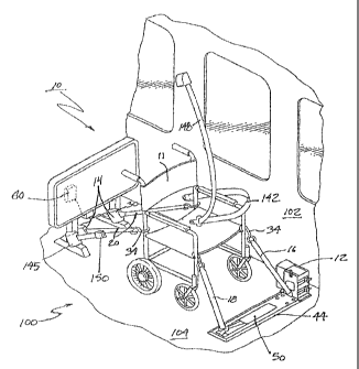
FIGURE 1 is a perspective view of the elements of the present invention in a
typical vehicle
environment.
FIGURE 2 is a perspective view of the main elements of the invention in a
typical vehicle
environment.
FIGURE 3 is a top view of the front tensioning assembly.
FIGURE 4 is an elevation view of the front tensioning assembly showing the
belts in the
extended position.
FIGURE 5 is a side view of the front tensioning assembly viewed from the
inboard side.
4
CA 02387065 2009-09-30
FIGURE 6 is a top view of the front tensioning assembly showing the belts and
hooks in
the stowed position.
FIGURE 7 is an elevation view of the front tensioning assembly, showing the
belts in the
stowed position.
FIGURE 8 is a side view of the front tensioning assembly, showing a stowed
belt and
hook, viewed from the inboard side.
FIGURE 9 is a perspective view of the control box.
FIGURE 10 is a perspective view of electrically powered rear tensioning
elements.
FIGURE 11 is a perspective view of manually operable rear tensioning elements.
DETAILED DESCRIPTION OF THE PREFERRED EMBODIMENT
With reference first to FIG. 1, a wheelchair station 100 is provided in a
vehicle having a
floor 104 and one or more side walls 102. The wheelchair station is located
between a front
tensioning assembly 12 and one or more rear tensioning assemblies 14. A
control system 60 is
provided for providing tension to the front tensioning assembly 12 and rear
tensioning assemblies
14. Together, the tensioning assemblies, with the associated controls and
wiring constitutes the
system 10 of the invention, designed to secure wheelchair 11 and its occupant
to the station 100.
With reference now to FIGS. 1-9, the detailed elements of the front tensioning
assembly 12
will be better understood. To provide suitable elements for securing and
tensioning the front portion
of a wheelchair 11, front tensioning assembly 12 comprises a front floor plate
44 secured to the
floor 104 of a vehicle utilizing fasteners 54 which may be screws, rivets,
bolts, or other well-known
fastening means. The front floor plate 44 includes an enclosure portion 48,
bevelled edges 46, and
cover plate 50 which is movable between an open position as shown in FIG. 3
and a closed
position as shown in FIG. 6. Associated with front tensioning assembly 12 is a
pair of tensioning
belts, front outboard belt 16 and front inboard belt 18, both of which are
provided with wheelchair-
engaging hooks 34 attached to belts 16 and 18 by outboard belt loop 35 and
inboard belt loop 37.
CA 02387065 2009-09-30
Belts 16 and 18 are routed through belt guides 38 and 40 respectively. Belt
guide 40 is attached to
pivot assembly 42. Pivot assembly 42 is hinged at hinge point 49 permitting
pivot assembly 42 to
articulate through angle 0. Belt guide 40 is attached to pivot assembly 42
through pivot pin 51,
thereby allowing belt guide 40 to rotate around the axis of pivot pin 51. In
this fashion, belt 18 and
belt guide 40 and pivot assembly 42 may be rotated into appropriate
orientation for stowing the hook
34, belt 18, belt guide 40 and pivot assembly 42 underneath coverplate 50 when
coverplate 50 is
in the closed position as shown in FIG. 6. Preferably, the position of belt
guide 42, belt 18 and belt
hook 34 are located on the opposite end of front floor plate 44 from belt
guide 38, and belt 16.
This positioning insures that lateral support is provided to the front of the
wheelchair 11 by belts 16
and 18 and their associated hooks 34.
As shown best in FIG. 4, a pivoting outboard belt guide 38 is affixed to front
drive housing
28, which is in turn affixed to front floor plate 44. It will be appreciated
that front floor plate 44 and
front drive housing 28 will be attached to the floor 104 of the vehicle using
appropriate fasteners 54
to insure that the front tensioning assembly 12 provides the necessary support
to restrain the
wheelchair 11 from movement in the event of a collision. The front drive
housing 28 is provided
with a hanger 36 adapted to support the hook 34 affixed to front outboard belt
16 when the front
tensioning assembly 12 is not in use.
Preferably, the front floor plate 44 is provided with bevelled edges 46 and
cover plate 50,
which, when the system is in its stowed or retracted position, provides a
relatively smooth and
unimpeding surface for other passengers to walk over without tripping. With
further reference to
FIGS. 1, 3 and 4, it will be appreciated that the configuration therein
displayed is typical of the
configuration in which the front tensioning assembly 12 would appear when in
use. The two hooks
34 appear in the position that they would occupy if engaged with the front
portion of a wheelchair 11.
Under these circumstances, belts 16 and 18 extend from one or more storage
reels located within
drive housing 28. Sufficient belt webbing is provided for belts 16 and 18 to
ensure that they may be
extended and retracted to accommodate a wide range of wheelchair styles and
sizes. Within housing
28 is a roller guide (not shown) which guides belts 18 and 16 onto one or more
storage reels (not
shown) to prevent belts 16 and 18 from fouling or jamming during extension and
retraction from and
to the belt reel within housing 28. Cover plate 50 preferably slides over
opening 53. The edges of
cover plate 50 engage the edges of opening 53 in a secure fashion to prevent
cover plate 50 from
lifting upward away from front floor plate 44, or from downward movement into
belt enclosure
6
CA 02387065 2009-09-30
portion 48 through opening 53. This result maybe easily accomplished by
providing a tongue and
groove-type engagement between the edges of opening 53and cover plate 50.
Cover plate 50 may
also be provided with additional guides and rollers (not shown) to provide a
low friction guiding
action to that portion of belt 18 which passes through the belt enclosure
portion 48.
In use, cover plate 50 is slid to the retracted position shown in FIG. 3,
exposing belt guide
40, pivot assembly 42, beltl8 and belt hook 34. Likewise, belt 16 and belt
hook 34 are removed
from their stowed position on hanger 36 and attached to the wheelchair 11 in
the approximate
orientation shown in FIG. 1. FIG. 5 shows a typical orientation of belt guide
40 and bolt guide 38,
with belts 16 and belt 18 removed for clarity.
With reference now to FIG. 1, as well as to FIG. 4, it will be easily
understood that tension
may be applied to belts 16 and 18, thereby drawing those portions of belts 16
and 18 located
between hooks 34 and guides 38 and 40 closer to guides 38 and 40, thereby
tending to pull a
wheelchair 11 affixed to hooks 34 in a forward direction. Assuming that the
rear of the wheelchair
11 is secured from the rear, belts 16 and 18 will thereby provide tension to
secure the wheelchair
11 from both forward and aft and lateral movement. In one embodiment, this
tension is provided
by front tension motor assembly 24 which is operatively coupled to a drive
mechanism (not shown)
located within front drive housing 28. In this embodiment, a simple gear train
provides a speed
reduction for motor assembly 24 and a corresponding increase in mechanical
advantage to the belt
storage reels contained within front drive housing 28. Motor 24 is operative
in both clockwise and
counter-clockwise directions, permitting tension on belts 16 and 18 to be
selectively applied and
released.
Although the preferred embodiment contemplates the use of electrical power as
the motor
driving source, it will be obvious to those skilled in the art that other
power sources, such as
pneumatic or hydraulic power may be used for motor 24. Further, as shown in
FIGS. 1 and 3,
belts 16 and 18 may be operated from separate storage reels driven by a common
motor assembly
24 utilizing the necessary separate drive gear trains within housing 28. It
can also be appreciated
from FIG. 3 and FIG. 5 that manual tensioning screws 56 may be provided to
manually drive the
necessary gear trains within housing 28 to manually tighten or loosen the
belts 16 and 18 when not
using a powered system or in the event of a power failure in the system. It
will also be appreciated
that it is beneficial to provide a drain 52 in floor plate 44 to permit water
and debris which may
7
CA 02387065 2009-09-30
collect within the belt enclosure portion 48 to be removed from the vehicle.
With reference now to FIGS. 2, 6 and 7, the stowed position of the front
tensioning
assembly belts will be easily understood. By providing sufficient tension to
belts 16 and 18, belts
16 and 18 and their associated hooks 34 are drawn toward belt guides 38 and
40. When fully
retracted, inboard belt hook 34 is stowed on hanger 36, and belt 18 and its
associated hook 34 are
stowed within belt enclosure portion 48. Cover plate 50 is slidably moved to
cover opening 53
which will enclose both belt 18 and its associated hook 34. Passengers in the
vehicle are then
presented with a relatively flat and unimpeding surface comprising front floor
plate 44 and cover
plate 50.
With reference now to FIG. 1 and 2, the orientation, mounting and operation of
rear
tensioning assemblies will be better understood. In the preferred embodiment,
two rear tensioning
assemblies 14 are provided with belts 20 and hooks 34. Again, it is desirable
to locate one rear
tensioning assembly 14 near the right rear of the wheelchair station 100 and
one near the left rear of
the wheelchair station 100, separated by sufficient distance to provide
lateral support to the
wheelchair 11 when the tensioning assemblies 14 are under tension. Within each
rear tensioning
assembly housing 30 is a spring biased reel adapted to spool and provide
selective tension to belts
20. Preferably, belts 20 can be extended or retracted selectively by pulling
on or releasing tension
from said belts. Again, hooks 34 are affixed to belts 20 by loops sewn in the
ends of belts 20.
As shown in FIGS. 10 AND 11, each rear tensioning assembly 14 is provided with
a belt
20 and a spring biased reel (not shown) within a housing 30 and cooperating
with the belt 20.
Each rear tensioning assembly is affixed to the vehicle using fasteners, such
as nuts 110, washers 111
and bolts 112, suitable for securing each rear tensioning assembly 14 to a
suitable anchor point 114
on the vehicle. In one embodiment, this attachment point may be the support
for a modesty panel 130
or seat frame. The rear tensioning assemblies 14 are provided with a selective
release mechanism
116 cooperating with the spring biased reel inside housing 30. In this
embodiment, the selective
release mechanism 116 is secured to the rear tensioning assembly 14. A pawl
within the selective
release mechanism 116 may be selectively engaged with a portion of the spring
biased reel,
selectively preventing or allowing movement of the spring biased reel.
Operation of the pawl within
the selective release mechanism 116 is regulated by a flexible cable assembly
118. The distal end
of each flexible cable assembly 118 engages a cable actuator assembly 120,
121. Cable actuator
8
CA 02387065 2009-09-30
assembly 120, 121 may be provided with power means, or may be operated
manually. Operation
of the cable actuator assembly 120, 121 applies or releases tension from cable
assemblies 118,
thereby selectively applying or releasing tension to the selective release
mechanism 116 associated
with each rear tensioning assembly 14. The cable actuator assembly 120,121 has
a "locked" and a
"release" position. When the cable actuator assembly 120, 121 is operated to
the "lock" position, no
tension is supplied to the cable assemblies 118, thereby allowing the pawl
within the selective
release mechanism 116 to be in its normally locked position, and preventing
the spring biased reel
within assembly 14 from movement. Operation of the cable actuator assembly
120, 121 to the
"release" position applies tension on the cable assemblies 118, causing the
pawl within the selective
release mechanism 116 to be withdrawn from engagement with the spring biased
reel, thereby
permitting the belt 20 to be extended or withdrawn into the housing 30 of the
rear tensioning
assembly 14.
The basic operation of the system is shown in FIG. I and FIG. 9, which
includes a
simplified and stylized view of both a front tensioning assembly 12, two rear
anchor assemblies 14
and a control box 60. In the preferred embodiment control box 60 includes both
a drive circuit and
a sensing or feedback circuit. The front tensioning assembly 12 is provided
with an electric motor
assembly 24, in the present embodiment, to provide rotational motion and the
necessary torque to
tension and relax the belts. It will be readily understood that providing
electrical power and controls
to such electric motor assemblies is a task easily accomplished by a micro
controller with associated
circuitry. Cooperating with the drive motor circuit is a sensing circuit which
is designed to measure
the amount of current being drawn by the electric motor in the invention.
Drive motor current is
known to be directly proportional to the motor torque, which in turn, is
directly proportional to
applied belt tension. It is known that when a desired belt tension is reached
that the desired current
level is also presented to the motor drive circuit. Referring to FIG. 9, a
micro controller unit within
the contol box 60 is preprogrammed to sense this desired current level, and to
turn off the drive
motor when this current level has been reached. The micro control unit is
completely automatic,
and will continue to sample the tension on the belts 16 and 18 when the system
is in operation.
When the micro controller unit determines that the belts 16 and 18 are
appropriately tensioned, it
will provide a signal in the form of indicator lights 68 which will visually
confirm for the wheelchair
occupant or vehicle operator that the wheelchair II is secured. The control
box 60 is provided
with a two-position selector switch 62. In one positions the system is
configured for tensioning of
the belts 16 and 18. In the other position, the system is configured for
release of the belts 16 and
9
CA 02387065 2009-09-30
18. After selecting the desired operation (tension or release) the start
switch 64 is utilized to
energize the circuit and provide the necessary drive signals to the tensioning
motor. In the tension
mode, if for some reason one or more belts 16 and 18 are not tensioned, the
two indicator lights 68
will illuminate simultaneously indicating that the system has malfunctioned.
The circuit is provided
with potentiometers for adjustments which allows the circuit to be easily
calibrated for different belt
tensions. In one embodiment, motor assembly 24 contains two separate motors.
Separate drive
circuits for each motor permit each belt 16 and 18 to be calibrated in such a
way as to be tensioned
independently from each other belt.
In operation, therefore, once the wheelchair 11 has been positioned in the
station, the
wheelchair occupant or the vehicle operator operates the system to release
tension and unstow each
of the belts from their retracted position and attach each associated hook to
the appropriate corner
portion of the wheelchair. If a manual cable actuator assembly 120 is included
with the system, the
wheelchair occupant or vehicle operator will move the cable actuator control
handle 124 to the
"lock" position, thereby restricting the rear belts 20 from further extension
from their respective
housings 30. If a powered cable actuator assembly 121 is included with the
system, actuation of the
selector switch 62 to the tension position locks the selective release
mechanisms 116. Once the four
belts have been so positioned, the wheelchair occupant or vehicle operator
will position the switch 62
to the tension position and operate switch 64. This operation sets into motion
the automatic
tensioning and feedback logic contained within the controller unit, sending a
"lock" signal to the
powered cable actuator assembly 121, driving the appropriate belt tensioning
motors of motor
assembly 24 to their desired tensions, thereby securing the wheelchair 11 from
both fore and aft and
lateral movement within the vehicle. Power to the motors is then removed,
effectively locking the
tensioning belts 16 and 18 in their desired tensioned position.
Release of the wheelchair from the wheelchair station is accomplished by
moving the switch
62 to the "release" position and operating the start switch 64 which results
in a release of the tension
on all belts, as a result of driving the motor 24 associated with the
tensioning assembly 12 in the
reverse direction from the tensioning direction. As soon as sufficient slack
has been created in the
belt tensioning system, the motors of motor assembly 24 are automatically de-
energized, allowing
the hooks 34 and belts 16 and 18 to be released from the wheelchair. If the
system is equipped
with the powered cable actuator assembly 121, at the same time, the powered
cable actuator
assembly 121 is provided with a "release" signal, actuating the selective
release mechanism 116 to
CA 02387065 2009-09-30
permit the rear belts 20 to be extended from and retracted into their housings
30. If the system is
equipped with the manual cable actuator assembly 120, the wheelchair occupant
or vehicle operator
will release the manual release handle 124 to accomplish the same result. Once
the hooks 34 and
belts 20, 16 and 18 have been released from the wheelchair, the switch 62 is
again moved to the
tension" position and the start switch 64 operated. Stops built into the rear
anchor assembly housing
30 prevents hooks 34 from retracting into the housing. Hanger 36 secures the
hook 34 associated
with belt 16 from retracting into guide 38. Guide 40 prevents hook 34 from
excess movement.
Accordingly, operation of the start switch 24 when a wheelchair 11 is no
longer located in the
wheelchair stationl00 results in application of tension to the front belts 16
and 18 to place them in
their fully retracted position, Once belt 18 is fully retracted, cover plate
50 can be positioned over
opening 53, thereby completing the stowing process.
Another aspect of the system shown in FIG. 1 is the provision for standard
occupant
restraints in association with the invention to insure that a wheelchair
occupant remain restrained in
the wheelchair 11 being secured to the vehicle according to the present
invention, in the form of
conventional seat belt elements 145, 142 and 148. A quick release buckle 150
allows for
securement and release of these conventional seat belt elements in relation to
the passenger.
Having described my invention in detail, it will nevertheless be obvious to
those skilled in the
art to make numerous minor modifications thereto without departing from the
essence of my
invention which I claim as follows:
11