Language selection

Search

Patent 2388931 Summary

Third-party information liability

Some of the information on this Web page has been provided by external sources. The Government of Canada is not responsible for the accuracy, reliability or currency of the information supplied by external sources. Users wishing to rely upon this information should consult directly with the source of the information. Content provided by external sources is not subject to official languages, privacy and accessibility requirements.

Claims and Abstract availability

Any discrepancies in the text and image of the Claims and Abstract are due to differing posting times. Text of the Claims and Abstract are posted:

  • At the time the application is open to public inspection;
  • At the time of issue of the patent (grant).
(12) Patent: (11) CA 2388931
(54) English Title: CARTRIDGE EJECTION DEVICE
(54) French Title: DISPOSITIF D'EJECTION DE CARTOUCHE
Status: Deemed expired
Bibliographic Data
(51) International Patent Classification (IPC):
  • A47J 31/44 (2006.01)
(72) Inventors :
  • KOLLEP, ALEXANDRE (Switzerland)
  • FISCHER, DANIEL (Switzerland)
  • STIEGER, MISCHA (Switzerland)
(73) Owners :
  • SOCIETE DES PRODUITS NESTLE S.A. (Switzerland)
(71) Applicants :
  • SOCIETE DES PRODUITS NESTLE S.A. (Switzerland)
(74) Agent: BORDEN LADNER GERVAIS LLP
(74) Associate agent:
(45) Issued: 2008-07-29
(86) PCT Filing Date: 2000-09-28
(87) Open to Public Inspection: 2001-05-03
Examination requested: 2005-06-20
Availability of licence: N/A
(25) Language of filing: English

Patent Cooperation Treaty (PCT): Yes
(86) PCT Filing Number: PCT/EP2000/009514
(87) International Publication Number: WO2001/030218
(85) National Entry: 2002-04-25

(30) Application Priority Data:
Application No. Country/Territory Date
99121440.4 European Patent Office (EPO) 1999-10-28

Abstracts

English Abstract


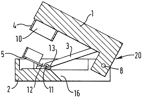
The present invention relates to a device for ejecting a cartridge of a coffee
machine comprising a jaw (20) with a
fixed part (2) and a moving part (1), the said jaw parts forming, in the
closed position, a housing (10) for the said cartridge on the
front of the said jaw, the moving part being mounted so that it can rotate on
the rear of the fixed part, the said device comprising, on
the fixed part, in the region of the cartridge housing, an ejector (5) and a
pulling arm (3) mounted on the moving part above the axis
of rotation of the said moving part with, at the end of the said arm, a first
pin (11) designed to collaborate with catch members (12,
13) of the ejector.


French Abstract

La présente invention concerne un dispositif qui sert à éjecter une cartouche d'une machine à café et qui comprend une mâchoire (20) dotée d'une partie fixe (2) et d'une partie se déplaçant (1), lesdites parties de la mâchoire constituant, en position fermée, un logement (10) pour ladite cartouche sur la partie avant de la mâchoire, la partie se déplaçant étant montée de telle manière qu'elle peut tourner sur la partie arrière de la partie fixe. Ledit dispositif comprend sur la partie fixe, dans la zone du logement de la cartouche, un éjecteur (5) et un bras qui tire (3) fixé sur la partie se déplaçant au-dessus de l'axe de rotation de cette partie pourvue au niveau dudit bras, d'une première broche (11) conçue pour collaborer avec des éléments de préhension (12, 13) de l'éjecteur.

Claims

Note: Claims are shown in the official language in which they were submitted.


-7-

CLAIMS:

1. Device for ejecting a capsule of a coffee machine
comprising a jaw with a fixed part and a movable part, the said
jaw parts forming, in the closed position, a receptacle for the
said capsule on the front of the said jaw, the movable part
being mounted rotatably on the rear of the fixed part, the said
device comprising, on the fixed part, at the position of the
capsule receptacle, an ejector mounted rotatably on an axis
just behind the capsule receptacle and a pulling arm secured to
the movable part above the axis of rotation of the said movable
part with, at the end of the said arm, a first pin designed to
cooperate with catch means of the ejector in order to lift the
said ejector.

2. Device according to claim 1, wherein the ejector consists
of an annular system comprising the catch means on a part of
the annular system.

3. Device according to claim 1 or 2, wherein the pulling arm
comprises a second pin axially aligned with the first pin, this
second pin being designed to cooperate with a guide cam of the
fixed part of the jaw.

4. Device according to any one of claims 1 to 3, wherein the
ejector comprises means for retaining the capsule.

5. Device according to any one of claims 1 to 4, wherein the
length of the fixed and movable parts of the jaw is between 10
and 30 cm.

6. Device according to any one of claims 1 to 5, wherein the
catch means consist of a recess terminating in the shape of a
hook.

Description

Note: Descriptions are shown in the official language in which they were submitted.


CA 02388931 2007-07-18
-1 -
Cartridge ejection device

TECHNICAL FIELD
The present invention relates to a device for ejecting
cartridges in a coffee machine comprising a jaw with a
fixed part and a moving part.

BACKGROUND OF THE INVENTION
Systems that allow the ejection of cartridges at the end
of extraction in coffee machines comprising a jaw are
already known. The principle is based on the presence of
an ejector in the lower part of the jaw and the pivoting
of the said ejector to remove the cartridge extracted,
when the said jaw opens. The drawback with the devices of
the state of the art is that the axis of rotation of the
ejector is too far away from the portion of coffee to be
removed, which leads to the said portion of coffee being
catapulted and, in falling, dirtying the machine, in the
case of the extraction of a closed cartridge which opens
under the effect of the rise in pressure during
extraction.

SUMlARY OF THE INVENTION
The object of the present invention is to optimize an
ejection device in which the catapult effect is avoided,
and in which the cartridge can be slipped into a waste bin
incorporated into the machine.

The present invention therefore relates to a device for
ejecting a cartridge of a coffee machine comprising a jaw
with a fixed part and a moving part, the said jaw parts
forming, in the closed position, a housing for the said
cartridge on the front of the said jaw, the moving part
being mounted so that it can rotate on the rear of the
fixed part, the said device comprising, on the fixed part,
in the region of the cartridge housing, an ejector and a


CA 02388931 2007-07-18

- 2 -

pulling arm mounted on the moving part above the axis of
rotation of the said moving part with, at the end of the
said arm, a first pin designed to collaborate with catch
members of the ejector.
The pin provided on the pulling arm may have any possible
geometrical shape. This pin preferably has a cylindrical
shape so that it catches well in the catch members, which
thus have a shape that complements that of the pin.
It is possible, in the device according to the invention,
to extract closed or open cartridges. By way of closed
cartridges, it is possible to envisage the cartridges that
form the subject of Patent EP 512 468 and EP 620 203 in
the name of the applicant. However, there is no limitation
on also being able to use the device according to the
invention for other sachets or cartridges or capsules
which are closed. It is also possible to use the device
according to the invention for open capsules, for example
capsules made of plastic or sachets made of filter paper
and of nonwovens.

The device according to the invention may also be
incorporated into any type of coffee machine designed for
cartridge or sachet extraction. It would be possible, for
example, to incorporate the device into the machine that
is the subject of Patent Application EP 99117107.5 filed
on 31 August 1999 in the name of the applicant.

The ejector of the device according to the invention
consists of a flat annular system comprising the catch
members on a part of the said annular system. These catch
members are preferably located on the side of the said
annular system and at right angles to the axis of rotation
of the said ejector. The axis of rotation of the ejector
is arranged just behind the cartridge housing, for example


CA 02388931 2007-07-18

- 3 -

at a distance of between 5 and 15 mm away from the
housing.

In a preferred embodiment, the pulling arm comprises a
second pin at the same level as the first pin, this second
pin being designed to collaborate with a guide cam of the
fixed part of jaw. As with the first pin, this may have
any possible geometric shape. As a preference, it has a
cylindrical shape identical to that of the first pin. The
guide cam of the fixed part of the jaw has an aperture
which just allows the said second pin to be introduced and
to move therein. This cam provides the pulling arm with
good guidance so as to have good ejection and good return
of the ejector to the initial position.
When the jaw opens, it is necessary that the cartridge
should not rise up with the moving part of the jaw. The
capsule needs to remain in the housing in the fixed part
of the jaw. To achieve this, means for retaining the
capsule are provided on the ejector. These means may be of
any kind. For example, it is possible to use the retaining
means which are the subject of Patent Application
EP 97202208.1 of 14 July 1997 in the name of the
applicant.
The size of the device according to the invention is not
critical. Consideration is normally given to a coffee
machine with fixed and moving parts of the order of 10 to
cm long.
The catch members have, on the one hand, to allow the jaw
to open and then they have to allow the used cartridge to
be ejected. They therefore consist first of all of a
recess allowing the pin to slide, and then of a hook,
allowing the pin to lift the ejector correctly.


CA 02388931 2007-07-18
- 4 -

BRIEF DESCRIPTION OF THE DRAWINGS
The remainder of the description is given with reference
to the drawings in which:

Fig. 1 is a part section of the device with the jaw
closed,
Fig. 2 is a diagrammatic view of Figure 1, from the other
side,
Fig. 3 is a part section of the device as it opens,
Fig. 4 is a diagrammatic view of Figure 3, from the other
side,
Fig. 5 is a diagrammatic face-on view of Figure 3,
Fig. 6 is a part section of the device, fully open,
Fig. 7 is a diagrammatic view of Figure 6, from the other
side, and
Fig. 8 is a diagrammatic depiction of the ejector viewed
from above.

DETAILED DESCRIPTION OF THE INVENTION
Figs. 1 and 2 show the device closed, Figs. 3 to 5 show
the device partially open, and Figs. 6 and 7 show the
device fully open. There is the jaw (20) with its moving
part (1) and its fixed part (2), the said jaw opening and
closing about an axis of rotation (8). The pulling arm (3)
with the second pin (7) in the guide cam (6) can be
clearly seen. This arm (3) rotates about the axis (9). The
housing (10) for the cartridge is formed by virtue of the
cage (4) on the moving part (1) of the jaw (20). The
ejector (5) is moved in rotation about the axis (14) by
virtue of the pin (11) of the pulling arm (3). The pins
(11) and (7) lie one in the continuation of the other.
They are normally of cylindrical shape. The ejector has a
recess (12) and a hook (13) to allow the said ejector to
pivot with the arm (3).


CA 02388931 2007-07-18
- 5 -

The way in which the device according to the invention
works is as follows: the consumer places the cartridge for
extraction (not depicted) on the fixed part (2) of the jaw
(20) in the region of the ejector (5), with the jaw in the
open position. He then closes the machine using the
device, not depicted, that is the subject of the
aforementioned Patent Application EP 99117107.5: the
cartridge is in the housing (10) formed by the cage (4).
He performs cartridge extraction in a way which we will
not describe now, because extraction does not form the
subject of the present invention. The consumer then acts,
in order to open the jaw, on the opening means which are
the subject of the aforementioned patent application. In
lifting, the moving part (1) of the jaw (20) carries along
the arm (3) and also the pin (11) at the end of the said
arm. As the jaw opens, the lower edge of the cartridge is
retained by means (17) so that it does indeed remain on
the ejector (5). In the first part of its travel, the pin
slides along the recess (12) of the ejector (5) and when
it reaches the position of Figs. 3 to 5, the said pin (11)
follows the interior shape of the hook (13) and lifts the
ejector (5). At this moment, the cartridge slides down the
chute (16) to the waste bin. When the ejector is high
enough up, the pin (11) uncatches from the hook (13) and
the ejector drops back down into the position of Figs. 6
and 7. The guide cam (6) with its pin (7) provides good
guidance for the pin (11) in the ejection and while the
ejector (5) is dropping back down.

Fig. 8 is a view in the direction of arrow A (Fig. 6)
giving a clear view of the ejector. This figure very
clearly shows its annular shape and the recess (12) and
the hook (13) for ejection. The plate (15) is a separate
part which comprises recessed and raised elements in the
event of closed cartridge extraction. The retaining means


CA 02388931 2007-07-18

- 6 -

(17) form an integral part of the ejector and are arranged
on the front of the fixed part (2) of the jaw (20).

The device according to the invention can be used on any
type of coffee machine comprising a type of extraction for
ready-to-use doses.

Representative Drawing
A single figure which represents the drawing illustrating the invention.
Administrative Status

For a clearer understanding of the status of the application/patent presented on this page, the site Disclaimer , as well as the definitions for Patent , Administrative Status , Maintenance Fee  and Payment History  should be consulted.

Administrative Status

Title Date
Forecasted Issue Date 2008-07-29
(86) PCT Filing Date 2000-09-28
(87) PCT Publication Date 2001-05-03
(85) National Entry 2002-04-25
Examination Requested 2005-06-20
(45) Issued 2008-07-29
Deemed Expired 2015-09-28

Abandonment History

There is no abandonment history.

Payment History

Fee Type Anniversary Year Due Date Amount Paid Paid Date
Registration of a document - section 124 $100.00 2002-04-25
Application Fee $300.00 2002-04-25
Maintenance Fee - Application - New Act 2 2002-09-30 $100.00 2002-08-22
Maintenance Fee - Application - New Act 3 2003-09-29 $100.00 2003-08-25
Maintenance Fee - Application - New Act 4 2004-09-28 $100.00 2004-08-24
Request for Examination $800.00 2005-06-20
Maintenance Fee - Application - New Act 5 2005-09-28 $200.00 2005-08-12
Maintenance Fee - Application - New Act 6 2006-09-28 $200.00 2006-08-18
Maintenance Fee - Application - New Act 7 2007-09-28 $200.00 2007-08-15
Final Fee $300.00 2008-05-08
Maintenance Fee - Patent - New Act 8 2008-09-29 $200.00 2008-07-31
Maintenance Fee - Patent - New Act 9 2009-09-28 $200.00 2009-08-13
Maintenance Fee - Patent - New Act 10 2010-09-28 $250.00 2010-08-23
Maintenance Fee - Patent - New Act 11 2011-09-28 $250.00 2011-09-06
Maintenance Fee - Patent - New Act 12 2012-09-28 $250.00 2012-08-08
Maintenance Fee - Patent - New Act 13 2013-09-30 $250.00 2013-08-14
Owners on Record

Note: Records showing the ownership history in alphabetical order.

Current Owners on Record
SOCIETE DES PRODUITS NESTLE S.A.
Past Owners on Record
FISCHER, DANIEL
KOLLEP, ALEXANDRE
STIEGER, MISCHA
Past Owners that do not appear in the "Owners on Record" listing will appear in other documentation within the application.
Documents

To view selected files, please enter reCAPTCHA code :


To view images, click a link in the Document Description column. To download the documents, select one or more checkboxes in the first column and then click the "Download Selected in PDF format (Zip Archive)" or the "Download Selected as Single PDF" button.

List of published and non-published patent-specific documents on the CPD .

If you have any difficulty accessing content, you can call the Client Service Centre at 1-866-997-1936 or send them an e-mail at CIPO Client Service Centre.


Document
Description 
Date
(yyyy-mm-dd) 
Number of pages   Size of Image (KB) 
Representative Drawing 2002-04-25 1 10
Abstract 2002-04-25 1 58
Claims 2002-04-25 2 42
Drawings 2002-04-25 3 48
Description 2002-04-25 5 212
Cover Page 2002-10-04 1 40
Description 2007-07-18 6 219
Claims 2007-07-18 1 37
Representative Drawing 2008-07-16 1 13
Cover Page 2008-07-16 2 48
PCT 2002-04-25 9 298
Assignment 2002-04-25 5 164
Prosecution-Amendment 2007-07-18 9 330
Prosecution-Amendment 2005-06-20 1 19
Prosecution-Amendment 2005-07-07 1 28
Prosecution-Amendment 2007-01-30 2 53
Correspondence 2008-05-08 1 31