Note: Descriptions are shown in the official language in which they were submitted.
CA 02400129 2007-12-19
. , ~
METHOD AND DEVICE FOR
SETTING CUSTOM DOOR TRAVEL LIMITS ON A
MOTORIZED GARAGE DOOR OPERATOR
TECHNICAL FIELD
Generally, the present invention relates to a garage door operator system for
use on
a closure member moveable relative to a fixed member. More particularly, the
present
invention relates to an operator-controlled motor for controlling the
operation of a closure
member, such as a gate or door, between a closed position and an open
position. More
specifically, the present invention relates to an operator-controlled motor
for a door or gate
operator, which allows for simplified custom setting of closure member travel
limits
BACKGROUND ART
For convenience purposes, it is well known to provide garage doors which
utilize a
motor to provide opening and closing movements of the door. Motors may also be
coupled
with other types of movable barriers such as gates, windows, retractable
overhangs and the
like. An operator is employed to control the motor and related fimctions with
respect to the
door. The operator receives command signals for the purpose of opening and
closing the
door from a wireless remote, from a wired wall station or other similar
device. It is also
known to provide safety devices that are connected to the operator for the
purpose of
detecting an obstruction so that the operator may then take corrective action
with the motor
to avoid entsapment of the obstruction.
A newer generation of operating systems have been found to provide improved
sensitivity to extraneous forces applied to a door during its movement. One
such device is
disclosed in U.S. Patent No. 6,161,438, which is assigned to the present
assignee of this
invention. Briefly, this patent discloses use
of a potentiometer coupled to the door for determining a plurality of
positional locations
between the open and closed positions. A processor contained in the operator
correlates the
position of the door with an applied force for use in comparison to a
predetamined
threshold. If, during movement of the door, the applied force is outside the
limits of the
predetermined titreshold, corrective action can be taken. With this increased
sensitivity,
CA 02400129 2002-08-28
l
-2-
safety standards allow use of the above operator system without an extemal
safety system
on anti-pinch doors. These motorized garage door operators are known to have
force adjustments that can
be either mechanically or electronically controlled. This allows the
installer, or the
consumer, a way of adjusting the force that the operator exerts on the door.
The amount of
force to move the door will vary with the weight of the door, but can also
vary as the
environment changes and as the door becomes worn with age. Generally, the
information
necessary to properly set these limits is contained in the
owner's/installation manual.
Manual adjustment or selection is provided to allow the user or the installer
of the door
operator to set position limits which coincide with the fully open and fully
closed positions
of the door, and to set sensitivity limits which permit sufficient torque to
move the door
throughout its complete range in both opening and closing direction, but not
enough torque
to damage the door. A given model of operator may be intended for use on light
doors,
which might be damaged by too much torque, as well as heavy doors. It is
important to
match the operator to the door by using the sensitivity setting to achieve
proper operation
without damage to the door.
The sensitivity setting and the position limits are also used in obstruction
detection
for stopping the door to prevent damage by or to the obstruction. By using the
maximum
sensitivity, which is consistent with proper door operation, the damage by or
to an
obstruction can be minimized. It is a requirement that an obstruction
detection feature be
utilized during door movement except for the last inch of travel prior to the
closed position.
Thus the closed position limit is useful in identifying the door position
above which
obstruction detection is enabled.
U.S. Patent No. 6,161,438 to Mullet, et al. discloses aninternal entrapment
system for
a door movable by a repeatable force that includes a force-generating device
for transferring
the door between a first and a second position. A trolley arm connected
between the force
generating device and the door is continually strained during movement of the
door. A
sensor mounted on the trolley atm generates a signal representative of the
strain applied to
the trolley arm. A processor receives the strain signal for comparison to a
predetermined
threshold, when the strain signal exceeds the predetermined threshold, the
processor at least
stops the force-generating device. A potentiometer is coupled to the door for
determining
a plurality of positional locations of the door between the first and the
second positions,
CA 02400129 2002-08-28
-3-
wherein the processor correlates the position of the door with the strain
signal for use in
comparison to the predetermined threshold. A power supply provides electrical
power to the
force generating device, the sensor, the processor, and the potentiometer, and
a
decoder/amplifier circuit, which also receives electrical power from the power
supply and
receives the strain signal for conversion into a format acceptable for use by
the processor.
U.S. Patent No. 6,107,765 Fitzgibbon, et al. discloses a movable barrier
operator that
includes a wall control switch module having a learn switch thereon. The
switch module is
connectable to a control unit positioned in a head of a garage movable barrier
operator. The
head unit also contains an electric motor, which is connected to a
transmission for opening
and closing a movable barrier such as a garage door. The switch module
includes a plurality
of switches coupled to capacitors which, when closed, have varying charge and
discharge
times to enable which switch has been closed. The control unit includes an
automatic force
incrementing system for adjusting the maximal opening and closing force to be
placed upon
the movable barrier during a learn operation. Likewise, end of travel limits
can also be set
during a learn operation upon installation of the unit. The movable barrier
operator also
includes an ambient temperature sensor which is used to derive a motor
temperature signal,
which motor temperature signal is measured and is used to inhibit motor
operation when
further motor operation exceeds or is about to exceed set point temperature
limits.
U.S. Patent No. 6,097,166 Fitzgibbon, et al. discloses a movable barrier
operator
which includes a wall control switch module having a learn switch thereon. The
switch
module is connectable to a control unit positioned in a head of a garage
movable barrier
operator. The head unit also contains an electric motor, which is connected to
a transmission
for opening and closing a movable barrier such as a garage door. The switch
module
includes a plurality of switches coupled to capacitors which, when closed,
have varying
charge and discharge times to enable which switch has been closed. The control
unit
includes an automatic force incrementing system for adjusting the maximal
opening and
closing force to be placed upon the movable barrier during a learn operation.
Likewise, end
of travel limits can also be set during a learn operation upon installation of
the unit. The
movable barrier operator also includes an ambient temperature sensor which is
used to
derive a motor temperature signal, which motor temperature signal is measured
and is used
to inhibit motor operation when further motor operation exceeds or is about to
exceed set
point temperature limits.
CA 02400129 2002-08-28
C
-4-
U.S. Patent No. 6,051,947 Lhotak, et al. discloses an operator for opening and
closing
movable barriers'such as garage doors comprising a pass point limit system,
which is a
component of an operating head. The operator is responsive to remote control
from a wall
panel or other location remote from the operating head to enable setting and
adjustment of
door travel limits from a remote location, without requiring installation of
limit switches
separate from the operating head.
U.S. Patent No. 5,278,480 Murray discloses a garage door operator that has a
microcomputer based control which is programmed to measure doorposition from
full open
position by counting motor revolutions and to determine motor speed and
deceleration for
each revolution. The program learns the open and closed position limits as
well as force
sensitivity limits for up and down operation with minimal user input. During
normal door
operation the closed limit and the sensitivity limits are adaptively adjusted
to accommodate
changes in conditions. The lowest up and down motor speeds in each operation
are stored
for comparison with motor speeds in the next like operation for obstruction
detection. Motor
deceleration is also monitored for obstruction detection. For a more sensitive
obstruction
detection during closing, the motor speed is mapped for each revolution for
the last several
inches of closing. The map is stored after each successful closing operation
and the
corresponding speeds in the next closing are compared point-by point with the
mapped
speeds to detect slow down due to touching an obstruction
U.S. Patent No. 4,831,509 Jones, et al. discloses a door controller for roller
type doors
that incorporate a microprocessor control system. The microprocessor measures
and stores
the door speed over segments of the door travel to generate a door speed
travel
characteristic. This characteristic enables the door controller to accurately
assess obstruction
conditions by comparing a real time characteristic with a stored
characteristic. The
microprocessor also stores electronically the upper and lower limits of door
travel. The
microprocessor monitors electric motor duty cycle to avoid overheating of the
motor and
possible burnout while also controlling locking of the drive mechanism when
the motor is
inoperative. The microprocessor is also used to set the radio control signal
code used to
activate the door drive mechanism, the setting procedure allows for immediate
verification
of the set code.
U.S. Patent No. 4,706,727 to Leivenzon, et al. discloses a door operator for
an
overhead garage door that has a reversible electric motor and a gear train
driving the door.
CA 02400129 2002-08-28
r..
-5- (
Limit stops are provided, one for the "up" limit and another for the "down"
limit. Each of
the limit stops is Independently zero setable to cut off current to the motor
at a pre-selected
position.
U.S. Patent No. 4,638,433 Schindler discloses a microprocessor controlled
garage
door operator which eliminates lower and upper limit switches on the garage
door in that
the upper and lower limits are set in a program mode of the microprocessor
with up and
down control switches by the operator. The settings of the door are stored in
the memory
of the microprocessor. The microprocessor also sets the force limits by
establishing them
slightly above the actual force required to move the door up and down and this
prevents the
forces to be set greater than required which could result in a dangerous
condition. An
external security switch is also connected to the microprocessor of the garage
door operator
to allow the door to be opened by those knowing the code. In program mode, the
user enters
in the 4-digit code and the 4 numbers are stored.
These methods have resolved a number of functional problems but the solutions
have
created other problems. Resetting the travel limits automatically does not
allow for
installations where a support beam for the superadjacent floor is located
where the door will
contact the support beam before the operator has set the upper limit. Custom
setting of
limits as described in Fitzgibbon, et al allow for a more precise position
setting but the
installer must hold the learn button - - at the operator head - - depressed
until the door has
reached the desired height then release the button to set the new height.
Further it is
common to not have the capability of setting the down limit. Normally the down
limit is
set as the door is moved in the closing direction until it reaches the floor
and stalls out or
the door cycle is started with the door in the closed position, in either
case, the door being
in contact with the floor sets the down limit. As mentioned before, if there
is buckling of
the ground during colder months the door may automatically reset for the up-
heaved floor
and then a gap will appear when the weather is warmer and the floor returns to
its original
height.
The practice of setting force limits with offsets large enough to anticipate
changing
conditions results in low sensitivity to the detection of obstructions. It is
preferred that such
an offset be small to attain high sensitivity. Thus another method of
accommodating
changes in door opening and closing force is desired. It is thus desirable to
automatically
CA 02400129 2002-08-28
1 ~
-6-
change the closed and open limit position to reflect the actual end of door
travel, and to
accomplish sucha change in limit without manually entering the program mode.
DISCLOSURE OF INVENTION
It is thus an object of the present invention to provide a system and method
for the
setting of custom door travel limits on a motorized door operator. A moveable
barrier,
which is commonly referred to as a door or gate, is of the type that is
moveable into an out-
of-proximity position with a fixed surface that is to be sealed relative to
the door. The door
or gate is coupled to a motorized operator which controls movement of the door
or gate.
It is a further object of the present invention, as set forth above, to
provide a
mechanism such as counter-balance springs coupled to the motor and the
operator to assist
in moving the barrier in a desired direction. It is yet another object of the
present invention,
as set forth above, to provide an up/down switch that generates control
signals that are
received by the operator. The up/down switch may be actuated by a hard-wired
control
button, a main remote control button, an alpha-numeric keypad, or the like.
It is still another object of the present invention, as set forth above, to
provide an
operator to utilize a force profile to monitor the operating characteristics
of the motor with
respect to barrier position during barrier travel. It is still a further
object of the present
invention, as set forth above, to provide an operator that initiates
corrective action whenever
the motor applies a force outside the predetermined threshold. It is an
additional object of
the present invention, as set forth above, to provide an operator which is
micro-processor
based that contains the necessary memory, hardware, and software for storing a
force
threshold and software routines for measuring forces for comparison to the
force threshold.
It is yet another object of the present invention to provide a potentiometer
that
detects the position of the movable barrier regardless of whether the motor is
coupled to the
operator or not. As such, it is the object of the present invention for the
operator to detect
door position regardless of whether movement is by the motor or manually. Yet
another
object of the present invention is to provide an installation button for
establishing a door
profile for opening and closing cycles of the barrier movement. Accordingly,
it is another
object of the present invention to provide a normal installation cycle when
the door is
CA 02400129 2002-08-28
. , ~ ~.~.
-7-
positioned to a fully closed position whereupon actuation of the installation
button causes
the operator to rinove the door to a full open position and then stop. The
operator then
energizes the motor to return the door to a closed position and then this
cycle is repeated to
verify the operational forces associated with door movement. The foregoing
procedure also
sets the door limits when the motor stalls out upon reaching the end portion
of the track
carrying the movable barrier and upon reaching the floor of the opening which
is enclosed
by the movable barrier.
It is still a further object of the present invention to provide a disconnect
system that
allows for selective engagement between the operator and the motor. In the
normal
connected position, the operator is in direct communication with motor and
monitors its
various functions and provides commands for starting, stopping and reversing
the motor as
needed. It is another object of the present invention to provide a
disconnected position for
the disconnect system wherein the motor is disconnected from the operator so
that
energization of the motor does not result in barrier movement. It is a further
object of the
present invention to allow for manual movement of the movable barrier in such
a manner
that the potentiometer continually communicates with the operator to advise of
door
position. It is still a further object of the present invention for the status
of the disconnect
system to be detected by the operator.
It is yet another object of the present invention to provide an up/down switch
for
enabling the operator to control the motor and instruct the motor to proceed
upwardly or
downwardly as needed. It is another object ofthe present invention to provide
the up/down
switch so that it is directly wired to the operator. Alternatively, a remote
up/down switch
may be used in the normal operation of the movable barrier, wherein the remote
operates
by either in&ared or radio &equency signals. It is another object of the
present invention
to provide for the setting of custom travel limits to accommodate building
obstructions or
for any reason deemed necessary by the end user. Therefore, it is an object of
the present
invention to allow for setting upper and lower limits of door travel, other
than the normal
stall limits, on a motorized door operator wherein the operator utilizes the
potentiometer and
the processor for generating and maintaining custom door operational profiles
by
positioning the door at a desired limit prior to initiating an installation
routine. It is another
object of the present invention to provide a method of setting the upper limit
of door travel,
CA 02400129 2002-08-28
i~.
-8-
other than the normal stall limit, on a motorized door operator where the
operational
controls utilize the potentiometer and the processor for generating and
maintaining a custom
door operational profile by initiating a signal during the first cycle of the
installation routine
to set the upper limit.
In general, the present invention contemplates a door operator for setting
limits on
movable barrier travel including a motor for moving the movable barrier
between two travel
positions, an operator for controlling operation of the motor, and a
disconnect system
coupled between the motor and the operator, wherein the disconnect system is
switchable
between a connected position and a disconnected position and wherein the motor
can
engage the operator only when the disconnect system is in the connected
position. A
potentiometer is associated with the operator for ascertaining movable barrier
position
regardless of the position of the disconnect system. The invention further
contemplates
setting a travel limit by placing the disconnect system in the disconnected
position and
manually moving the door to a desired position whereupon the disconnect system
is moved
to the connected position so that the operator can detect a positional
location to be
designated as one of the travel limits. The operator may also be associated
with an
installation switch so that the operator can determine either a lower or upper
limit from the
desired position as detected by the potentiometer, wherein actuation of the
installation
switch establishes the respective travel limit. The particular travel limit is
determined by
where the door is manually moved with respect to the overall size of the
opening.
The invention also contemplates a door operator which incorporates an up/down
switch for enabling the operator to control operation of the motor. The
setting of a limit
with the up/down switch is implemented by first actuating the installation
switch which
begins establishment of an operational profile and wherein actuation of the
up/down switch
during establishment of the operational profile sets a travel limit for the
movable barrier as
determined by the potentiometer. The invention also contemplates that the
lower limit is
set by using the aforementioned disconnect system, and then the upper limit is
set by using
the up/down switch.
The invention further contemplates a method for setting travel limits for a
motorized
movable barrier for an opening controlled by an operator, wherein the position
of the
movable barrier is monitored by a potentiometer and wherein a disconnect
system is
CA 02400129 2002-08-28
. ~ ~
-9-
interposed between the operator and the motor. The method employs the steps of
disconnecting the movable barrier from the operator by disengaging the
disconnect system
and manually positioning the movable barrier to a desired travel limit which
is observed by
the potentiometer and communicated to the operator. The method is completed by
re-
connecting the movable barrier to the operator and re-engaging the disconnect
system
whereupon the operator stores the desired travel limit. Upon completion of the
aforementioned steps an installation switch may be connected to the operator
where
actuation of the installation switch after the reconnecting step initiates
generation of the
operational profile from the desired travel limit. Depending upon where the
movable barrier
is manually positioned determines whether an upper or lower limit is being
set. Another
method contemplated by the present invention utilizes actuation of an up/down
switch after
actuation of the installation switch that is establishing an operational
profile to determine
a travel limit. The travel limit is detected by the potentiometer and stored
in a processor
carried by the operator whereupon the installation routine continues for
establishment of the
operational profile. The foregoing methodologies may also be used to first set
the lower
limit by disconnecting the disconnect system, manually moving the door to a
lower limit,
reconnecting the disconnect system, and then actuating the installation
button. The method
then continues by setting an upper limit by actuation of the up/down button in
the manner
described above.
These and other objects of the present invention, as well as the advantages
thereof
over existing prior art forms which will became apparent from the description
to follow, are
accomplished by the improvements hereinafter described and claimed.
BRIEF DESCRIPTION OF THE DRAWINGS
For a complete understanding ofthe objects, techniques and structure ofthe
invention,
reference should be made to the following detailed description and
accompanying drawings,
wherein:
Fig. 1 is a perspective view depicting a sectional garage door and showing an
operating mechanism embodying the concepts of the present invention;
Fig. 2 is an enlarged fragmentary schematic view of the operator mechanism of
Fig.
CA 02400129 2002-08-28
-10-
1 as viewed from the inside of the sectional garage door;
Figs. 3A and 3B are perspective drawings showing a disconnect system in a
disconnected state and connected state;
Fig. 4 is an operational flow chart employed by the operator of the present
invention
for setting a new lower limit;
Fig. 5 is an operational flow chart employed by the operator of the present
invention
for setting a new upper limit with an existing limit already in memory; and
Fig. 6 is an operational flow chart employed by the operator of the present
invention
for setting a new upper limit with no upper limit in memory.
BEST MODE FOR CARRYING OUT THE IIWENTION
A system and related methods for setting custom door travel limits on a
motorized
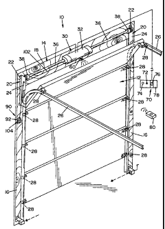
garage door operator is generally indicated by the numeral 10 in Fig. I of the
drawings. The
system 10 is employed in conjunction with a conventional sectional garage door
generally
indicated by the numeral 12. The door 12 may be an anti-pinch or pinch type
door. The
opening in which the door is positioned for opening and closing movements
relative thereto
is surrounded by a frame, generally indicated by the numeral 14, which
consists of a pair
of a vertically spaced jamb members 16 that, as seen in Fig. 1, are generally
parallel and
extend vertically upwardly from the ground (not shown). The jambs 16 are
spaced and
joined at their vertically upper extremity by a header 18 to thereby form a
generally u-
shaped frame 14 around the opening for the door 12. The frame 14 is normally
constructed
of lumber or other structural building materials for the purpose of
reinforcement and to
facilitate the attachment of elements supporting and controlling the door 12.
Secured to the jambs 16 are L-shaped vertical members 20 which have a leg 22
attached to the jambs 16 and a projecting leg 24 which perpendicularly extends
from
respective legs 22. The L-shaped vertical members 20 may also be provided in
other shapes
depending upon the particular frame and garage door with which it is
associated. Secured
to each projecting leg 24 is a track 26 which extends perpendicularly from
each projecting
leg 24. Each track 26 receives a roller 28 which extends from the top edge of
the garage
door 12. Additional rollers 28 may also be provided on each top vertical edge
of each
CA 02400129 2007-12-19
11
section of the garage door to facilitate transfer between opening and closing
positions.
A counterbalancing system generally indicated by the numera130 may be employed
to move the garage door 12 back and forth between opening and closing
positions. One
example of a counterbalancing system is disclosed in U.S. Patent No.
5,419,010.
- Generally, the counter-balancing system 30 includes a
housing 32, which is affixed to the header 18 which contains an operator
mechanism
generally indicated by the numera134 as seen in Fig. 2. Extending from each
end of the
operator mechanism 34 is a drive shaft 36, the opposite ends of which are
received by
tensioning assemblies 38 that are affixed to respective projecting legs 24.
Carried within
the drive shaft 36 are counterbalance springs as described in the '010 patent.
Although a
header-mounted operator is specifically discussed herein, the control features
to be
discussed later are equally applicable to other types of operators used with
movable barriers.
For example, the control routines can be easily incorporated into trolley type
operators used
to move garage doors.
The drive shaft 36 hansmits the necessary mechanical power to transfer the
garage
door 12 between closing and opening positions. The drive shaft 36 provides a
drive gear
42 at about a midpoint thereof wherein the drive gear 42 is coupled to a motor
gear 44.
Driving motion of the motor gear 44 is controlled through a gear box 46 by a
motor 48 in
a manner well known in the art.
A control circuit 50, which is contained within the housing 32, monitors
operation of
the motor 48 and various other elements contained within the operator
mechanism 34 as will
be described hereinbelow. Batteries 52 may be connected to the drive motor 48
for the
purpose of energizing the motor 48 and the control circuit 50 to provide any
power required
for the operation thereof. An external power source may also be used to
energize the motor.
A potentiometer generally indicated by the numera156 is connected to the drive
gear
42 for the purpose of determining positional location of the door 12. The
potentiometer 56
may also be employed to provide a speed value for the garage door as it
travels between
opening and closing positions. To this end, a slider 58 extends from the
potentiometer 56
and is coupled to the drive gear 42 to monitor the positional rotation of the
drive gear. A
sensor 60, which may either be ultrasonic or infrared, is employed to monitor
travel of the
gatage door 12. The sensor 60 is also connected to the control circuit S0 for
communication
CA 02400129 2002-08-28
-12-
therewith and to stop operation of the counterbalancing system 30 when deemed
appropriate.
A pulse counter (not shown) is employed to monitor rotation and speed of the
motor
48 in a manner well lcnown in the art. The pulse counter is connected to the
control circuit
50 for the purpose of supplying input thereto and allowing the control circuit
50 to take
corrective action when required.
It will be appreciated that the control circuit 50 employs a processor which
receives
power from the batteries 52 or from some other appropriate power supply. The
processor
includes the necessary hardware, software, and memory to implement operation
of the
control circuit 50. The potentiometer is also connected to the processor where
it can be
seen that the potentiometer includes different points with the slider 58
disposed
therebetween. In essence, the potentiometer 56 is a variable resistor, wherein
the end points
have an electrical potential slider across them. If the slider is moved toward
the end point
with the positive potential, then the slider voltage becomes more positive. If
the slider is
moved towards the other end point with the negative potential, then the slider
voltage
becomes more negative. By connecting the slider to the door 12 through the
drive gear 42,
the potentiometer 56 always outputs a voltage relative to the position of the
door 12. If the
power supply, for whatever reason, is removed from the control circuit, the
slider still points
to a position relative to the door. If a user moves the door while the
operator mechanism
34 is off, the slider maintains a relitive position with respect to the door
and is reacquired
once power is returned to the operator mechanism 34. In this manner, the
processor
contained within the operator can determine a force setting for each
positional location of
the door as it travels through its movement. From this, a force threshold
envelope can be
developed which accounts for parasitic drag, changes in temperatures which may
possibly
require a much higher (or much lower) power requirement, either of which can
cause a
phantom entrapment detection. Accordingly, the force threshold envelope
encompasses this
range of values.
Operation of the door is initiated by actuation of a control device. As seen
in Fig: 1,
the control device may either be a wall station 70 or a remote control switch
80. It will be
appreciated that the control devices may include other functions for
programming the
operator, controlling lights associated with the operator and other operator-
related functions.
CA 02400129 2002-08-28
i f
[.
-13-
Once the garage door, motor, and operator are installed in place, the wall
station 70
is placed in a convenient location. The set-up mechanic then initiates a set-
up procedure to
set the upper and lower limits of the door travel and also to set an
operational profile. As
discussed in U.S. Patent No. 5,929,580, the operational profile is regularly
updated and
employed as a safety feature to stop travel of the door in the event of an
obstruction. Briefly
setting of the operational profile and the door travel limits is accomplished
by first placing
the door in the fully closed position and then inserting a tool (not shown)
into the access
hole. This actuates a hidden door installation button 72 that starts the door
travel in the up
direction. Once an upper limit is set -- when the motor stalls out due to the
door hitting the
end of the track -- the motor and door reverse direction to determine where
the lower limit
is located. The door then repeats the open/close cycle to set the operational
profile and,
upon completion of the procedure, the profile is set. Briefly, the operational
profile is
sequence of force measurements for incremental door positions in either
direction of door
travel. During regular operation, if a force measurement at a particular door
position is
outside of an acceptable force measurement range, the door is at least stopped
and, if
desired, reversed. Upon completion of each successful door travel cycle, the
operational
profile is updated. This allows for any minimal changes in force, such as
motor wear, to be
accounted for in the profile. In any event, completion of the installation
procedure may be
indicated by flashing of an LED 74. Upon completion of the setup procedure,
the door and
operator are ready for use. It will be appreciated that use of the foregoing
set-up procedure
eliminates the need for the mechanic to access programming features that were
previously
only accessible at the operator. Moreover, the mechanic can now be in a safer
location,
away from the operator and motor, during set-up.
Refening now to Figs. 3A and 3B, a disconnect system, generally indicated by
the
numera190, is shown. The disconnect system 90 functions to disengage the motor
from the
operator primarily for safety reasons. In the event the motor wears out or is
otherwise
rendered inoperable, disengagement of the operator from the motor allows the
user to
manually open and close the door as needed. The disconnect system 90 includes
a bracket
92 that is secured to the jamb member 16, preferably in a position high enough
so that it
cannot be reached by children. The bracket 92 is secured to the jamb member 16
by
conventional means such as threaded fasteners or nails. The bracket 92 has a
CA 02400129 2007-12-19
-14-
perpendicularly extending flange 94 which has a hole 96 extending
therethrough. The
bracket 92 also lias a perpendicularly extending arm 98 which is essentially
parallel and
below the flange 94. The arm 98 provides a slot 100 which may have a tapered
entry as
shown. A disconnect cable 102 is connected at one end with linkage that
connects and
disconnects the operator from the motor as disclosed in U.S. Patent No.
6,253,824.
The other end of the cable 102 is connected to a handle
104. The disconnect handle has a collar 106 from which extends a T-section
108. Two
different positions are provided by the disconnect system 90. As shown in Fig.
3B, the
system is in a connected position wherein the collar 106 is positioned
adjacent the flange
94. The handle 104 and cable 102 are assembled such that the cable is captured
within the hole 96 so that it cannot travel any further than as show. When it
is desired to disconnect
the operator from the motor, the user pulls on the T-section 108 and moves the
cable in such
a fashion that the collar 106 bears against the bottom surface of the arm 98.
The cable fits
in the slot 100 and is retained therein. When it is desired to re-engage the
operator with the
motor, the user pulls on the handle slightly and repositions the handle so
that the collar 106
bears against the flange 94.
Referring back to Fig. 1 it can be seen that included with the wall station 70
is an
up/down button 76. The wall station may also be provided with a light
actuation button 78
for turning on an overhead light if desired. Remote control 80 may also be
provided to
actuate the operator with either an infiared or radio frequency signal. The
remote 80
essentially functions in the same manner as the up/down button 76, it may or
may not be
used in setting of the travel limits.
Referring now to Fig. 4, an operational flow for setting a custom lower limit
is
designated generally by the numeral 120. As a first step in seTting a new
lower limit of door
travel, for example, to provide ventilation and or to overcome any permanent
obstructions
positioned at the floor of the opening, at step 122, the disconnect system 90
is accessed so
as to move the handle 104 into a disconnected position as shown in Fig. 3A. At
step 124,
the banier is manually moved to a desired custom closing position wherein this
position is
typically less than the midpoint ofthe entire opening. In standard garage
doors it is believed
that this position limit will be less than four (4) feet above the floor.
While the door is
manually moved, the potentiometer 56 keeps track of the door position by
virtue of its
CA 02400129 2002-08-28
1.,.
-15-
engagement with the drive shaft 36. In any event, once the desired door
position is
obtained, the handle 104 is repositioned at step 126 to a connected position
as shown in Fig.
3B.
At this time, the set-up mechanic or user actuates the installation button 72
at step
128. At step 129 the operator determines whether the bottom edge of the door
is below the
enclosure's mid-point height. If it is determined that the door is above the
mid-point, then
the operator, at step 130, ends the installation mode. This is done to prevent
the setting of
a lower limit that would allow more than half of the garage door opening to be
accessible
and also to prevent confusion with the upper travel limits. If, at step 129,
it is determined
that the door is below the enclosure's mid-point height, then, at step 132,
the operator marks
that location, as determined by the potentiometer, as the new custom lower
limit. At step
134, the operator continues with the install routine to set the other limit
and the rest of the
operational profile.
When it is desired to set a new upper limit when there is an upper limit
already
provided in the operator memory, the operator executes the procedural steps
shown in Fig.
5 and which is designated generally by the numeral 140. First, the user
disconnects the
motor from the operator by positioning the handle 104 to the disconnected
position as
shown Fig. 3A. At step 144 the door is manually moved to a desired upper limit
other than
the normal install limit primarily for the purpose of avoiding any
obstructions that now
extend down from the ceiling or otherwise impede the movement of the door at
the end of
an opening cycle. In any event, the disconnect systezn 90 is re-engaged at
step 146 such that
the handle 104 is placed in the position as shown in Fig. 3B. It is believed
that the door will
be positioned in the upper half of the opening which is typically more than
four (4) feet
above the floor. At step 147 the installation button 72 is pressed and the
operator re-
engages with the motor. The installation routine is commenced such that the
operator
accepts the repositioned door as the new upper limit. Accordingly, at step 148
the operator
confirms the position of the door and if the door position is not above the
enclosures
opening, then, midpoint at step 150, the installation mode is ended and the
operator is
returned to its normal operating mode. However, if at step 148 it is
determined that the
door is positioned above the enclosures opening midpoint, then at step 152
that position is
marked as the upper limit and the operator continues with the installation
mode.
CA 02400129 2002-08-28
-16-
Referring now to Fig. 6, the procedure for setting a new upper limit where
there is no
upper limit in memory is generally indicated by the numeral 160. First, the
door is located
in the closed position adjacent the flopr as indicated at step 162. At step
164 the user
activates the installation button 72 and the door begins establishing an
operational profile.
The mechanic or user observes the door travel at this time and at step 166
they push the
up/down button 76 to set the upper limit. If no special upper limit is
required then the door
will be allowed to stall as noted in the prior art. Once the door stops, the
operator, at step
168, determines whether the door is located above the enclosure's mid-point
which is
typically four feet. If the door is not above the enclosure's mid-point, then
the installation
procedure is ended at step 170. If the door is above the enclosure's mid-
point, then at step
172, that position is designated as the operator's upper limit by the operator
which then
continues with the installation routine to set the other limit and the rest of
the operational
profile.
If desired, both a custom lower limit and a custom upper limit can be set
during a
single installation procedure. The procedure for doing so is set forth in
Figs. 4 and 6.
Setting of the custom lower limit proceeds as shown in the operational flow
120. At step
134, the set-up procedure may continue as indicated by a transfer step 200
which continues
on at step 166 for the purpose of setting the custom upper limit.
From the foregoing methods and the operator's interaction with the other
components,
it will be appreciated that this invention has several advantages. The
aforementioned
system allows for the setting of both the upper and lower limits with the
capability of
manually resetting both the upper and lower limit for custom setting when
special needs
arise that interfere with the travel of the door but would otherwise not
hinder use of the
door. These procedures allow for custom setting of the upper and lower limits
without
stalling out the positioning of the door which upon inducing stress on the
motor and the
door panels. The potentiometer allows for the permanent setting of the custom
limits and
these settings remain even if there is a loss of power to the operator.
Accordingly, the lower
limit may be positioned at any point between the floor and a midpoint and an
upper limit
can be set anywhere from the midpoint and above.
Thus, it should be evident that the method and device for setting custom door
limits
for a motorized garage door operator disclosed herein carries out the various
objects of the
CA 02400129 2002-08-28
f
-17-
present invention set forth above and otherwise constitutes an advantageous
contribution
to the art. As will'be apparent to those persons skilled in the art,
modifications can be made
to the preferred embodiments disclosed herein without the parting of the
spirit of the
invention. Therefore, the scope of the invention herein described shall be
limited solely by
the scope of the attached claims.