Note: Descriptions are shown in the official language in which they were submitted.
CA 02402125 2002-09-17
TITLE OF THE INVENTION
Angle-based method and device for protecting a rotating
component
FIELD OF THE INVENTION
1~ The present invention relates to the general field of rotating
machines and is particularly concerned with an angle-based protection device
and method for protecting a rotating component part of a machine.
BACKGROUND OF THE INVENTION
The prior art is replete with various types of machines having
rotating components for industrial, domestic, recreational and other purposes.
Because of particular physical phenomenons associated with rotating
movements, rotating components part of various types of machines are subjected
to particular operational parameters that may be potentially damaging
especially
when the rotating components reach critical angular values. The potential for
subjecting rotating components to damaging conditions is sometimes
compounded when the rotating components are used for imparting a rotational
movement to material contained therein, such as for mixing, grinding or other
purposes.
So-called grinding mills constitute a typical example of a machine
having a rotating component, namely a rotating drum that may be subjected to
potentially damaging conditions upon operational parameters of the machine
meeting pre-determined critical parameter conditions while the rotating drum
reaches a critical angular value. Such grinding mills are used extensively for
reducing lumps or large pieces of various kinds of material to smaller sizes.
1
CA 02402125 2002-09-17
Conventional grinding mills commonly include a hollow cylindrical or
frusto-conical shell or drum mounted for rotation about its longitudinal axis.
The
drum is typically rotatably arranged about two trunnions by two head portions
positioned at opposite longitudinal ends of the drum.
Typically, each conical head portion includes a plurality of segments
bolted together to form a composite structure. Each head portion is also
typically
provided an inner annular flange and an outer annular flange for securing the
head portions respectively to a trunnion and to the drum.
Also, conventional grinding mills are typically provided with a gear
wheel forming part of the gear mechanism that drives the grinding mill. The
gear
wheel commonly includes a plurality of segmental rim portions that are bolted
together to form an annular rim. Gear teeth are cut into the rim and shaped
for
cooperation with one or more pinions. The annular rim is typically displaced
radially outward of the drum by a rib. The rib is usually provided with a
plurality of
apertures through which bolts may pass to fasten the rib to the outer annular
flange of the head portion and the flange of the drum.
The gear wheel typically forms part of a large speed-reducing gear
system intended to transmit the power from a prime mover to the grinding mill.
The prime mover, in turn, typically includes an electrical prime mover such as
synchronous electrical motors or the like having enhanced starting torque
characteristics. In order to compensate for enhanced starting torque, the gear
wheel typically has a relatively large diameter.
Different diameters and lengths of shells or drums have been used
heretofore, and they normally vary in proportion to the capacity of the mill.
During
rotation of the drum about its longitudinal axis, the material to be ground is
2
CA 02402125 2002-09-17
carried up the side of the drum to subsequently fall to the bottom of the
drum.
The grinding occurs principally by attrition and impact within the grinding
mill
charge.
In the case of ore, the normal function of the grinding mill is to
reduce the size of the ore to particles within a fine sieve range for
flotation.
Grinding mills used for grinding ores or the like optionally use grinding
mediums
such as pebbles, steel balls, ceramic balls, or the like to assist in the
comminuting process as the mill is rotated.
In other circumstances, the ore may be self-grinding. The axial
ends of the drum may be open, and the material to be comminuted may be
continuously fed into the mill at one end with the comminuted product
continuously emerging from the other end.
In view of the abrasive character of the material being ground, the
wear on the inside of the grinding mill has heretofore been a serious problem.
Hence, in order to protect the drum from the grinding action and to thereby
lengthen the life of the grinding mill, the drum is typically provided with a
metal or
rubber lining. For example, grinding mills have been lined with cast or
wrought
abrasion-resistant ferrous alloy liners and, in some cases, rubber or ceramic
liners. Typically, these liners are segmented due to the weight and size
considerations.
Liner assemblies hence typically include a plurality of separate
lining components that are usually retained tightly against the interior or
the mill
shell or drum by mechanical fastening components such as bolts. Some ores,
such as taconite, are relatively highly abrasive. In order to maintain
continuous
operation of the grinding mill, it is necessary to provide a liner for the
drum that is
3
CA 02402125 2002-09-17
highly abrasion-resistant. The liner also should be tough enough to withstand
the
continuous impact of ore fragmerits.
Liners inevitably become worn and, hence, no longer effective. In
such situations, the liners are typically replaced at periodic intervals.
Other types
of maintenance and repair also periodically require the grinding mill to be
run at
speeds considerably slower than the normal running speed or even to stop the
rotation movement of the drum altogether.
As a result of mill shut-dowri over a period of time, the charge within
the mill may "freeze" into a generally solidified, hardened or rigid lump.
Upon the
mill being rotated after a mill shut-down there exists the possibility that
the
solidified lump will be carried up the side of the drum by the rotation of the
latter.
In such instances, instead of tumbling in a cascading flow upon reaching the
position wherein non-solidified charge would cascade, the mass may eventually
detach itself from the inner wall of the drum and fall on an impacting
location
within the drum.
This may prove to be detrimental to various components of the mill
including the lining, heads and bearings thereof. Also, since gear wheels are
typically constructed with great accuracy, they may also be subjected to
deformation by the impact. As can be appreciated, when the lining is affected
or
when a tooth in a gear wheel is damaged, the liner and the wheel must be
replaced. The cost of the occurrence of such events is very burdensome. Not
only is the cost of material and repair involved extensive but the high
capitalization costs of plants using large autogenous mills may be mobilized
by
extended non-productive down-time.
4
CA 02402125 2002-09-17
A solidified mass failing from the mill inner wall upon rotation of the
latter constitutes a typical example of a rotating component that may be
subjected to potentially damaging conditions upon the rotating component
reaching a critical angular value. Another example of angle-dependent
potentially damaging conditions may result from the potential mismatch between
actual load and designed torques.
Indeed, as the mill is rotated to the cascade position wherein the
charge starts to tumble, the torque required increases quite considerably as
the
charge is moved away from the gravity-balanced position on a large radius.
Once the charge begins to tumble, the required load torque drops. If the
developed motor torque matches the load torque plus the friction torque, then
the
rotation will be smooth and continuous.
It would be desirable to provide an angle-based protection device
for protecting rotating component and corresponding supporting component part
of machines. More particulariy, in some situations the rotating component
defines a critical angular value about which an operational parameter of the
machine may be used for predicting the occurrence of a potentially damaging
condition for the machine. Also, sometimes the potentially damaging condition
for the machine is concurrently more susceptible to happen upon the
operational
parameter meeting predetermined critical parameter conditions while the
rotating
component reaches a critical angular displacement value. In such situations,
it
would be desirable to provide an angle-based protection device for reducing
the
risk of such potentially damaging conditions occurring.
As mentioned previously, it is some times desirable to run the
grinding mill at speeds considerably slower than the normal running speed.
5
CA 02402125 2002-09-17
Typical examples include for the purpose of assuring proper gear, bearing and
shaft alignment when a mill is first being installed, also for inspecting and
potentially replacing the mill liner when the mill is empty or to start the
mill after it
has been stopped with a full charge. This slow running is often referred to as
"spotting", "inching", "barring" or "turning gear".
Heretofore, inching has been accomplished in several ways. One
of the simplest mechanical device used for inching includes a cable sling
arrangement attached to an overhead crane. The cable sling arrangement allows
for selective mill rotation. However, such a prior art technique is not
precise.
Also, it requires continuous use of a crane. Furthermore, it is dangerous to
personnei who may be installing or re-lining the mill as slings have a known
tendency to break.
Another way to provide for inching uses a low frequency power
source to provide power to the stator windings of the typically used three-
phase
synchronous drive motors. The low frequency power source may be a direct
current (DC) supply connected to an inching supplied bus for the motors
through
a series of electromechanical or static switches to produce stepped low
frequency three-phase voltages. These switches are typically referred to as
sequencing or commutating switches. The switches, however, are relatively
costly.
Inching has heretofore also been accomplished through the use of
clutches, the clutches may be partially engaged to cause rotation of the mill
at
lower speeds. This partial clutch closure for long periods however generates
considerable heat in the clutches and requires that the wet clutches be
installed
6
CA 02402125 2002-09-17
and provision made to dissipate the heat generated. Also, typically, an
installation using wet clutches is more expensive than one using dry clutches.
Yet, another way to provide for inching is to use a removable
hydraulic motor that is placed to engage main mill pinion gear. The present
invention is particularly well suited for use with such inching devices.
However, it
can be appreciated by those skilled in the art that the present invention has
broader applications and be used in conjunction with other types of machinery
for
obtaining an angle-based protection device.
SUMMARY OF THE INVENTION
Advantages of the present invention include that the proposed
angle-based protection device and method is intended to prevent angle-based
potentially damaging conditions from damaging rotating components. For
example, the proposed angle-based protection device and method can be used
for preventing a solidified mass within a conventional grinding mill from
impacting
the mill and damaging the latter upon rotation of the mill drum. The proposed
device may also be used for preventing damages caused by actual load torque
and designed torque mismatches or any other angle-based potentially damaging
conditions.
The proposed device may be readily installed on conventional
machines such as conventional grinding mills, inching devices or the like,
through
a set of quick and ergonomic steps. The proposed device and method may also
be easily retrofitted to existing machines without requiring undue work and
with
reduced risks of damaging the machines.
The proposed method and device is intended to protect the
machine with reduced interference to its operational parameters so as to
provide
7
CA 02402125 2009-08-24
a device having reduced risks of lowering the efficiency of the machine on
which
it is mounted. Also, the proposed method may be accomplished through the use
of various types of devices including devices readily commercially available.
Furthermore, the proposed device is designed so as to be
manufacturable using conventional forms of manufacturing so as to provide an
angle-based protection device that will be economically feasible, long-lasting
and
relatively trouble-free in operation.
According to an aspect of the present invention, there is provided a
method for protecting a grinding mill, at startup from a gravity-balanced
condition
thereof, including a rotatable mill drum used for grinding material from
damages
potentially caused by a lumped volume of said material falling from a fall
position
within said mill drum and impacting an impact position within said mill drum
upon
rotation thereof at startup from the gravity-balanced condition, said mill
drum
being coupled to a torque provider able to generate a driving torque for
rotating
said mill drum, said method comprises the steps of:
- assessing a presence of a potentially damaging lumped volume of said
material in said mill drum by evaluating if said material within said mill
drum is
tumbling in a cascading flow upon rotation of said mill drum at startup from
the
gravity-balanced condition;
- initiating an action for stopping the rotation of said mill drum upon
determination that said material within said mill drum is not tumbling in said
cascading flow under the presence of said potentially damaging lumped volume
of said material.
Typically, the step of evaluating if said material within said mill drum
is tumbling in a cascading flow upon rotation of said mill drum includes:
8
CA 02402125 2009-08-24
- estimating a cascading angular displacement range of said mill drum
from a startup position corresponding to the gravity-balanced condition within
which said material within said mill drum is expected to separate from an
inner
surface of said mill drum and tumble in a cascading flow upon rotation of said
mill
drum;
- evaluating if said material within said mill drum separates from said inner
surface of said mill drum within said cascading angular range upon rotation of
said mill drum.
Typically, the step of evaluating if said material within said mill drum
separates from said inner surface of said mill drum within said cascading
angular
range upon rotation of said mill drum includes:
- using said torque provider for rotating said mill drum with said material
contained therein;
- monitoring the value of said driving torque for the presence of a torque
value indicating that said material has not separated from said inner surface
of
said mill drum when said mill drum has rotated from the startup position at
the
gravity-balanced condition more than said cascading angular displacement
range.
Preferably, the step of monitoring the value of said driving torque for
the presence of a torque value indicating that said material within said mill
drum
has not separated from said inner surface of said mill drum within said
cascading
angular displacement range includes evaluating if said driving torque reaches
a
predetermined torque threshold when said mill drum has rotated from a gravity-
balanced condition more than said cascading angular displacement range.
9
CA 02402125 2009-08-24
Alternatively, the step of monitoring the value of said driving torque
for the presence of a torque value indicating that said material within said
mill
drum has not separated from said inner surface of said mill drum within said
cascading angular displacement range includes evaluating if said driving
torque
continues to increase when said mill drum has rotated from a gravity-balanced
condition more than said cascading angular displacement range.
In one embodiment, the method further comprises the steps of:
- assessing for a presence of a residual lump of material having remained
adhered to said inner surface of said mill drum beyond said cascading angular
displacement range despite a complementary volume of material having
separated from said inner surface of said mill drum;
- stopping the rotation of said mill drum upon assessing the presence of
said residual lump of material.
Typically, the value of said driving torque is monitored for the
presence of a torque value indicating the presence of said residual lump of
material when said mill drum has rotated from the startup position at the
gravity-
balanced condition more than said cascading angular displacement range, said
driving torque being monitored until said mill drum rotates from said gravity-
balanced condition by a predetermined safe angular displacement.
Typically, monitoring the value of said driving torque for the
presence of a torque value indicating the presence of a residual lump of
material
when said mill drum has rotated from a gravity-balanced condition more than
said
cascading angular displacement range includes evaluating if said driving
torque
continues to increase when said mill drum has rotated from a gravity-balanced
condition more than said cascading angular displacement range until said mill
CA 02402125 2009-08-24
drum rotates from said gravity-balanced condition by said predetermined safe
angular displacement.
According to another aspect of the present invention, there is
provided a method for protecting a grinding mill at startup from a gravity-
balanced
condition thereof, said grinding mill including a rotatable mill drum defining
a
drum inner surface and being coupled to a torque provider able to generate a
driving torque for rotating said mill drum, said grinding mill being used for
grinding
material by rotating said mill drum so that said material adhering to said
drum
inner surface rises therewith over a cascading angular displacement range from
startup at the gravity-balanced condition prior to being detached by gravity
from
said drum inner surface and tumbling into a cascading flow, said method being
used for protecting said grinding mill from damages potentially resulting from
said
material agglomerating into a generally solidified lumped volume that could
adhere to said drum inner surface and rotate with the latter from said gravity-
balanced condition more than said cascading angular displacement range to a
fall angular displacement wherein said lumped volume may detach from said
drum inner surface and impact an impact position within said mill drum, said
method comprises the steps of:
- assessing for a presence of material adhering to said drum inner surface
upon rotation of said mill drum by more than said cascading angular
displacement range from a startup position corresponding to said gravity-
balanced condition;
- initiating an action for stopping the rotation of said mill drum upon
determination of material adhering to said drum inner surface upon rotation of
said mill drum by more than said cascading angular displacement range from
11
CA 02402125 2009-08-24
said gravity-balanced condition under the presence of said material adhering
to
said drum inner surface.
Typically, the step of assessing for a presence of material adhering
to said drum inner surface upon rotation of said mill drum by more than said
cascading angular displacement range from a startup position corresponding to
said gravity-balanced condition includes:
- monitoring an angular displacement of said mill drum from said startup
position at the gravity-balanced condition and the value of said driving
torque;
- evaluating if the value of said torque continues to increase upon said mill
drum rotating from said startup position at the gravity-balanced condition by
said
cascading angular displacement range;
and wherein the step of initiating an action for stopping the rotation of said
mill drum upon determination of material adhering to said drum inner surface
upon rotation of said mill drum by more than said cascading angular
displacement range from said gravity-balanced condition includes:
- initiating an action leading to the stopping of the inching of said mill
drum
if the value of said torque continues to increase upon said mill drum rotating
from
said gravity-balanced condition by said cascading angular displacement range.
In one embodiment, the method further comprises the steps of:
- continuing to evaluate if said driving torque continues to increase when
said mill drum has rotated from said startup position at the gravity-balanced
condition more than said cascading angular displacement range until said mill
drum rotates from said gravity-balanced startup position by a predetermined
safe
angular displacement;
12
CA 02402125 2009-08-24
- initiating an action for stopping the inching of said mill drum if the value
of
said torque continues to increase when said mill drum has rotated from said
gravity-balanced startup position more than said cascading angular
displacement
range and less than said predetermined safe angular displacement.
In one embodiment, the cascading angular displacement range is
estimated by obtaining data on the value of said driving torque at various
angular
displacements of said mill drum from said gravity-balanced startup position
when
said mill drum is rotating and said material is tumbling in a cascading flow,
approximating said cascading angular displacement range to an angular
displacement of said mill drum from said gravity-balanced startup position
wherein the value of said driving torque is comparatively high relative to the
value
of said driving torque at other angular displacements of said mill drum from
said
gravity-balanced startup position.
According to another aspect of the present invention, there is
provided a device for protecting a grinding mill, at startup from a gravity-
balanced
condition thereof, including a rotating mill drum used for grinding material
from
damages caused by a potentially damaging lumped volume of said material
falling from a fall position within said rotating drum and impacting an impact
position within said rotating drum upon rotation thereof at startup from the
gravity-
balanced condition, said rotating drum being coupled to a torque provider able
to
generate a driving torque for rotation of said rotating drum, a presence of
said
potentially damaging lumped volume of said material being predictable upon an
operational parameter of said grinding mill being in relation with said
rotating
drum meeting predetermined critical parameter conditions corresponding
thereto,
said device comprises: a parameter sensor operatively coupled to said grinding
13
CA 02402125 2009-08-24
mill for providing an evaluation of said operational parameter upon said
rotating
drum moving at startup from the gravity-balanced condition, said parameter
sensor assessing the presence of said potentially damaging lumped volume of
said material from the evaluation of said operational parameter meeting said
predetermined critical parameter conditions; an effectuator operatively
coupled to
the torque provider and to said parameter sensor for receiving an assessment
of
the presence of said potentially damaging lumped volume of said material
thereform, said effectuator initiating an action for reducing the risks of
damaging
said grinding mill upon reception of the assessment of the presence of said
potentially damaging lumped volume of said material.
In one embodiment, the rotating drum has a drum peripheral wall
defining a peripheral wall reference location and an inner surface thereof;
and
said rotating drum defines a critical angular displacement value within which
said
material within said rotating drum is expected to separate from said inner
surface
of said rotating drum and tumble in a cascading flow upon rotation of said
rotating
drum and about which said operational parameter of said grinding mill may be
used for predicting the occurrence of a potentially damaging condition for
said
grinding mill in relation with said rotating drum reaching said predetermined
critical parameter conditions; said parameter sensor including an angle
evaluator
for providing an evaluation of an angular displacement relationship between
said
peripheral wall reference location and said critical angular displacement
value of
said rotating drum from a startup position corresponding to the gravity-
balanced
condition.
14
CA 02402125 2009-08-24
In one embodiment, the parameter sensor further includes: a torque
evaluator for evaluating said driving torque relative to said angular
displacement
relationship during rotation of said rotating drum from said startup position.
Typically, the angle evaluator includes a rotation encoder
operatively coupled to said grinding mill for converting an operational
parameter
of said grinding mill into an estimate of the angular displacement of said
rotating
drum from the startup position at said gravity-balanced condition.
In one embodiment, the rotation encoder includes: a reference
component mounted on a driving shaft of said torque provider for rotating
therewith; an inductive-type sensor mounted adjacent said reference component
for monitoring a displacement of said reference component and inferring the
angular displacement of said rotating drum from the displacement of said
reference component.
In one embodiment, the torque evaluator includes a torque
transducer operatively coupled to an inching device of said torque provider
for
assessing a torque provided by said inching device.
Typically, the inching device includes a hydraulic motor, said torque
transducer is a pressure transducer operatively coupled to a hydraulic
circuitry of
said hydraulic motor for assessing a hydraulic pressure in the hydraulic
circuitry
and provide to determine the torque provided by said hydraulic motor.
Conveniently, the rotation encoder is mounted on said inching
device.
Alternatively, the torque provider is an electrical driving motor
coupled to said grinding mill, or an inching device including a hydraulic
driving
motor.
CA 02402125 2009-08-24
Other objects and advantages of the present invention will become
apparent from a careful reading of the detailed description provided herein,
within
appropriate reference to the accompanying drawings.
BRIEF DESCRIPTION OF THE DRAWINGS
An embodiment of the present invention will now be disclosed, by
way of example, in reference to the following drawings in which:
Figure 1, in a partially broken schematic top plan view, illustrates
the protection device in accordance with an embodiment of the present
invention,
the protection device being used with a conventional hydraulic inching device
coupled to a conventional grinding mill;
Figure 2, in a transverse cross-sectional view of the drum part of
the grinding mill shown in Fig. 1, illustrates, in a diagrammatic manner, an
exemplary cascading and tumbling disposition of grinding media and material
being ground thereby during the rotation of the mill in the direction of the
arrow
shown adjacent the Figure;
Figure 3, in a transverse cross-sectional view of the drum shown in
Fig. 2, illustrates, in a diagrammatic manner, an exemplary disposition of the
grinding material and media when the latter is idle in gravity-balanced
condition;
16
CA 02402125 2002-09-17
Figure 4, in a transverse cross-sectional view of the drum shown in
Figs. 2, and 3, illustrates, in a diagrammatic mL;nner, an exemplary
disposition of
the grinding material and media, fully solidified, is into an undesired
position
requiring more torque than the normal cascading operation;
Figure 5, in a transverse cross-sectional view of the drum shown in
Figs. 2, 3 and 4, illustrates, in a diagrammatic manner, an exemplary
disposition
of the solidified lump falling from the inner surface of the drum during the
rotation
of the mill in the direction of the arrow shown in the Figure;
Figure 6, in a transverse cross-sectional view of the drum shown in
Figs. 2, 3, 4 and 5 illustrates, in a diagrammatic manner, an exemplary
disposition of the grinding material and media having a partially solidified
lower
portion reaching an undesired position also requiring more torque than the
normal cascading operation;
Figure 7, in a graph, illustrates the typical relationship between the
required driving torque and the drum rotation angle upon initiation of an
inching
process starting when the load is within the drum in an idle condition and
ending
when the load tumbles in a cascading flow;
Figure 8, in a diagram, illustrates the typical relationship between
the driving torque and the rotation of the drum starting when the load is
within the
drum in an idle condition, the load being either normal, partially solidified
or fully
solidified; and
Figure 9, in a schematic diagram, illustrates a sequence of steps
part of an angle-based protection method in accordance with an embodiment of
the present invention.
17
CA 02402125 2002-09-17
DETAILED DESCRIPTION OF THE PREFERRED EMBODIMENTS
With reference to the annexed drawings a preferred embodiments
of the present invention will be herein described for indicative purpose and
by no
means as of limitation.
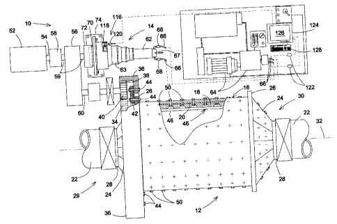
Referring to Fig. 1, there is shown a protection device generally
indicated by reference numeral 10 in accordance with an embodiment of the
present invention. The protection device 10 is shown being used with a
conventional grinding mill 12 and a conventional hydraulic inching device 14.
It
should be understood that this type of installation merely represents one type
of
exemplary installation through which the concepts of the subject invention may
be intended to be used and wiil allow those skilled in the art to more readily
appreciate the general gist of the application for the proposed protection
device.
The protection device 10 may be used in other environments in conjunction with
other types of machinery without departing from the overall intent or scope of
the
present invention.
The grinding mill 12 includes a hollow mill drum 16 having a drum
peripheral wall 18 defining the drum wall inner surface 20. The mill drum 16
is
rotatably arranged about two trunnions 22 by a pair of conical heads 24
positioned at opposite ends of the mill drum 16. Each head 24 is provided with
an inner annular flange 26 and an outer annular flange 28 for securing the
head
respectively to mill drum 16 and to an adjacent trunnion 22.
Preferably, the mill drum 16 defines a feed end area or face 29 and
an opposed discharge end area or face 30. The mill drum 16 is preferably
generally horizontally journalled to the trunnions 22 so as to be rotatably
driven
18
CA 02402125 2002-09-17
about its longitudinal axis 32 and typically extends in a generally slightly
tilted or
sloped orientation from horizontal.
The grinding mill 12 is typically further provided with a gear ring or
wheel 34 forming part of the gear mechanism for driving the grinding mill 12.
The
gear wheel 34 commonly includes a plurality of segmental rim portions that are
bolted together to form an annular rim 36. Cut into the rim 36 are teeth 38
cooperating with one or more pinions 40. Typically, the annular rim 36 is
placed
radially outward of the drum of the mill drum 16 by a rib 42.
The rib 42 is usually provided with a plurality of rib apertures
extending therethrough for allowing bolts 44 to fasten the rib 42 to the inner
annular flange 26 of the head 24 and the flange of the mill drum 16.
A lining 46 is typically provided over the drum inner surface 20 to
protect the latter from the grinding action and thereby lengthen the life of
the
grinding mill 12. The lining 46 may take any suitable form such as an assembly
of modular longitudinal lining sections or an assembly of elongated slabs 48
preferably having wedge-shaped ribs 49 or the like thereon. The slabs 48 are
forcibly held in place with radially extending fasteners 50. The lining 46 may
be
made out of any suitable material such as a suitable abrasive and impact
resistant metal alloy or even elastomeric resin.
The grinding mill 12 is mechanically coupled to a prime mover able
to provide a driving torque for rotating the mill drum 16. The prime mover
typically includes an electrical-type of mover having enhanced starting torque
characteristics. The prime mover typically includes an electric drive motor 52
enclosed in a drive motor housing.
19
CA 02402125 2002-09-17
The driving motor 52 includes a motor driving shaft 54 typically
operatively communicating with a gear reducer structure 56 enclosed within a
reducer housing via a motor clutch 58 operatively coupled to a reducer input
shaft
59. A reducer output shaft 60 extends outwardly from the reducer 56. The
reducer output shaft 60, or conventional pinion shaft, operatively
communicates
with the drive pinion gear 40. The drive pinion gear 40, in turn, is typically
journalled in driving communication with bull or girth teeth 38 of the gear
ring 34.
Although the gear reducer 56 is preferred, the driving motor shaft 54 could
alternatively be directly coupled to the pinion shaft 60.
Typically, the prime mover may include a pair of motors generating
several thousands of horsepower for applying a relatively large torque at
relatively slow speeds. The gear ring 34 typically has a relatively large
diameter
in order to compensate for enhanced starting torque. Also, the reducer 56
provides an output torque to the reducer output shaft 60 at a greater value
and
lower speeds than that of the driving shaft 54. The torque requirements will,
of
course, vary substantially between various mill installations and designs.
In use, typically, the grinding mill 12 is charged with the ore, rock or
other material to be ground through an opening within the feed end area 29,
preferably at the center thereof. As the ore, rock or other material is ground
to
the appropriate or desired size, it is discharged from the mill drum 16
through a
similar discharge opening at the discharge end area 30. Typically, the ground
material passes through a chute-like area (not shown) for transport to
subsequent
processing stations. Typically, the mill drum 16 is rotated about its
longitudinal
axis 32 so that the material being grourid is continuously tumbled within the
mill
drum 16 and thereby pulverizes or breaks itself to the necessary size.
Optionally,
CA 02402125 2002-09-17
water or other solids and/or liquids, such as conventional manganese balls or
the
like, may be added to the material.
The grinding mill 12 is optionally releasably operatively coupled to
the inching device 14 for allowing the grinding mill 12 to be run at speeds
considerably slower than the normal running speed. The slow running of the
grinding mill 12 often referred to as "spotting" or "inching" may be
accomplished
in several ways. Clutches may be used for coupling the prime mover through the
grinding mill 12. These clutches may be partially engaged to cause rotation of
the grinding mill 12 at lower speeds. Alternatively, low frequency power
sources
may be used to provide power to the stator windings of three-phase synchronous
drive motors. The lower frequency power source may be a direct current (DC)
supply connected to an inching supplied bus for the motors through a series of
electro-mechanical or static switches to produce stepped low frequency three-
phase voltages.
A third method for providing inching uses a removable hydraulic
motor positioned so as to engage the reducer input shaft 59 or be mechanically
coupled thereto. This third method of providing inching is illustrated in Fig.
1.
The inching device 14 includes a hydraulic motor 62 combined with an inching
brake assembly (not shown) which is typically a holding-type brake. Typically,
the hydraulic motor 62 is a high-efficiency hydraulic motor coupled to a multi-
stage planetary-type gear reducer 63. Typically, the inching brake assembly
includes spring applied hydraulic released brakes. However, the hydraulic
motor
62 may be of any suitable type without departing from the scope of the present
invention.
21
CA 02402125 2002-09-17
The hydraulic motor 62 and its associated inching brake assembly
are hydraulically coupled to an appropriate hydraulic pump and motor 64
through
conventional hydraulic fluid lines 66. Optionally, mix-proof quick-disconnect
couplings 68 may be used for coupling the hydraulic fluid lines 66 to the
casing of
the hydraulic motor 62. Typically, the brake assembly is mechanically biased
to a
braking condition and hydraulically actuated to a non-braking condition. The
requisite hydraulic fluid lines 67 for the brake assembly are schematically
shown
in Fig. 1.
The hydraulic motor 62 includes a hydraulic motor output shaft 70.
The hydraulic motor output shaft 70 is mechanically coupled to the reducer
input
shaft 59 through suitable coupling means such as a mounting hub 72 provided
with hub teeth (not shown) for mechanicai and directional engagement with
shaft
teeth (not shown) formed on the outer surface of the reducer input shaft 59.
Typically, the hydraulic motor 62 and corresponding brake
assembly is mounted on a motor mounting bracket 74.
Again, it should be understood that any suitable type of inching
device may be used without departing from the scope of the present invention.
Referring now more specifically to Fig. 3, when the mill drum 16 is
idle, the charge including the materiai to be ground and optionally
solids/liquids
as well as a grinding charge form a mass 76 at the bottom of the mill drum 16
having a somewhat irregular although generally horizontal top surface 78. The
height of the top surface 78 and, hence, the amount of loading respective to
the
cross-sectional area of the mill drum 16 will depend upon various operational
parameters. Hence, the particular loading shown in Figs. 2 to 6 is only shown
by
22
CA 02402125 2009-08-24
way of example and other loading configurations and volumes could be used
without departing from the scope of the present invention.
When a loaded grinding mill 12 is being inched, the rotation begins
on the "rest", "idle" or "gravity-balanced" startup position shown in Fig. 3.
As the
mill is rotated according to arrow 80 in Fig. 2, a leading portion of the load
82 in
contact with the lining 46 is carried upwardly according to arrows 84 up to a
so-
called cascading angular displacement 86. Since the grinding medium and
subject material form a generally coherent mass, most of the load 82 will be
moved by the rotation of the milling drum 16. Optionally, wedge-shaped ribs 49
or other suitable topographically enhancing means facilitate the carrying of
the
grinding medium and subject material with the drum during rotation thereof so
as
to enable the tumbling/cascading of the grinding medium and subject material,
thereby creating the grinding action.
The material to be ground is carried up the side of the mill drum 16
to subsequently fall to the bottom of the drum 16 when the cascading
displacement 86 is reached. The grinding occurs principally by attrition and
impact within the grinding mill charge 82.
At the cascading angular displacement 86, the resultant forces
acting on the charge 82 including friction, coherent and centrifugal forces
tending
to carry the load 82 up the side of the milling drum 16 and the gravitational
and
flowing forces tending to force the load 82 towards the bottom of the milling
drum
16 cause the inner portion 88 of load 82 to tumble downwardly. Since the load
82 is typically relatively fluent, the outer portion 88 of load 82 will
typically tumble
in a cascading flow assuming somewhat the direction and configuration shown in
Fig. 2. The material being generally fluent, tumbling of the top surface 78
will
23
CA 02402125 2002-09-17
cause elements within the load 82 to fall upon other elements so as to enhance
the crushing operation of the mill and produce a somewhat turbulent movement
of the mass.
When a grinding mill 12 is being inched without a load or charge, for
example to inspect the mill liners, the torque required is relatively constant
and of
a lesser value than required for normal running. However, when the grinding
mill
12 is being inched, the required torque varies depending on the angular
position
of the leading edge of the load 82, as well as on the quantity of charge 82
therein.
Referring now more specifically to Fig. 7, there is shown that when
a loaded mill is being inched with the rotation beginning from the idle
position, the
initial torque 90 required to begin rotation is relatively small. The initial
torque 90
is typically required only to overcome friction and start the rotation of the
milling
drum 16. The torque requirements then typically decrease slightly as indicated
at
92 when static friction is partially overcorne. The required torque then
begins to
increase as drum mill 16 rotates and raises the load 82, with increasing mill
angle a, which had settled at the bottom when the mill was stopped in the
gravity-
balanced position. The torque continues to increase as indicated at 94 since
the
load is rotated farther away from the bottom position it had when the mill
drum 16
was stopped, as illustrated in Fig. 3.
As the mill drum 16 is rotated or inched up by the cascading
angular displacement 86 at which the charge 82 starts to tumble, the torque
required increases quite considerably as the charge 82 is moved away from the
gravity-balanced position on a large radius. Although shown in Fig. 2 as being
typically about forty-five (45) degrees from the gravity-balanced position
(shown
in Fig. 3 with a=0 degree), the cascading angular displacement 86 forming the
24
CA 02402125 2002-09-17
cascading angle ac could vary to be other angular displacements depending on
the type and the quantity of material being ground without departing from the
scope of the present invention.
When the load 82 within the mill drum 16 cascades, as shown in
Fig. 2, the torque requirement slightly decreases such as shown at 96 untill a
generally steady state or constant torque 98 is reached.
Obviously, the sloped portion ramped portion 94 must reach the
steady or constant level 98 before the maximum load 100 is reached. In other
words, before the load 82 is expected to cascade.
Depending on the gear ratios and the type of motors used, the
ramped portion 94 may be associated with various time intervals after inching
has
started. In practice, as the load 82 in the milling drum 16 can be determined
only
with relatively poor accuracy before inching and, since the cascading angular
displacement 86 varies, it is difficult to provide an accurate ramp reference
prior
to inching.
Fig. 4 illustrates a situation wherein a fully solidified mass 102 has
formed because of prolonged idling or other conditions. When such a condition
occurs, the solidified mass 102 may be prevented from tumbling in a cascading
flow at the cascading angular displacement 86 and remain attached to the
lining 46.
In such situation, the mill 12 must be stopped from rotating and
preferably held in that position to remedy to the potentially damaging
situation
otherwise a portion 104 or the totality of the solidified mass 102 may detach
itself
suddenly from the lining 46 at a somewhat remote location from the bottom of
the
grinding drum 16 and fall according to arrows 106 on the lining 46, as shown
in
CA 02402125 2002-09-17
Fig. 5. The fall of a relatively heavy mass may cause serious damages to
various
components of the grinding mill 12 including the lining 46, the driving gears
and
other important components.
Accordingly, the torque requirements continue to increase past the
cascading angular displacement 86 as the solidified mass 102 is moved even
further away from the gravity-balanced position on the large radius of the
lining
46. Hence, instead of peaking at the cascading angular displacement 86 as
designated by reference 100 in full lines, the required torque continues to
increase as indicated at 108 due to the solidified mass 102, as shown in
dashed
lines in Fig. 7. Obviously, the initial sections of the ramped line are
somewhat
similar to the situation wherein the mass 102 eventually tumbles in a
cascading
flow at the cascading angular displacement 86.
Alternatively, as shown in Fig. 6, the solidified mass 102a can
represent only a bottom or lower portion of the load 82. The solidified mass
102a
will make the torque requirements to increase again after the constant torque
98
has been reached slightly following the start of the cascading on the non-
solidified portion of the load 82, as represented by the second ramped dotted
line
112 of Fig. 7. This situation can occur either when the solidified mass 102a
is a
portion of the load 82 or when the fully solidified mass 102 has only
partially
detached from the drum lining 46 and a remaining portion still remains
solidified
and attached to the drum lining 46. The partial detachment of the solidified
mass
102 from the drum lining 46 is illustrated by the negative sloped dashed line
at
110 in Fig. 7, followed by the dotted line '112.
The proposed method and device typically makes use of the
relationship between the required torque and drum rotation to assess the
26
CA 02402125 2002-09-17
presence of a solidified mass 102 that may potentially damage the grinding
mill
12, as schematically shown in the diagrani of Fig. 9.
In situations wherein the method is used in the context of a grinding
mill such as hereinabove disclosed, the proposed method includes the steps of
assessing for the presence of a potentiaily damaging lump volume of material
102 in the mill drum 16 by evaluating if the material within the mill drum 16
is
tumbling in a cascading flow upon rotation of the mill drum 16. The method
further includes the step of initiating an action for stopping the rotation of
the mill
drum 16 upon determination that the material within the mill drum 16 is not
tumbling in a cascading flow. More specifically, the step of evaluating if the
material within the mill drum 16 is tumbling in a cascading flow upon rotation
of
the latter may include the steps of initially estimating a cascading angular
displacement range 86 within which the material within the mill drum 16 is
expected to separate from the inner surface 20 of the mill drum 16 and tumble
in
a cascading flow upon rotation of the mill drum 16 from a gravity-balanced
condition. Once the cascading angular displacemerit range 86 has been
estimated, the method includes the step of evaluating if the material within
the
mill drum 16 separates from the inner surface 20 of the mill drum 16 within
the
cascading angular displacement range 86 upon rotation of the mill drum 16 from
a gravity-balanced position.
It should be understood that although the material within the drum
16 is hereinafter disclosed as potentially separating from the inner surface
20 of
the mill drum 16, the description also applies to situation where the material
separates from the lining 46 or any other covering material protecting the
inner
surface 20 of the mill drum 16.
27
CA 02402125 2002-09-17
In accordance with one aspect of the present invention, the step of
evaluating if the material within the rnill drum 16 separates from the inner
surface
20 within the cascading angular displacement range 86 upon rotation of the
mill
drum 16 from the rest or gravity-balariced position includes using a torque
provider (such as the primary drive motor 52 or the inching device 14) for
rotating
the mill drum 16 with the material contained therein. Once the mill drum 16 is
rotating, the next step involves monitoring the value of the driving torque
for the
presence of a torque value indicating that the material has not separated from
the
inner surface 20 of the drum mill 16 when the mill drum 16 has rotated from
the
'r 0 gravity-balanced position by more than the cascading angular displacement
range 86. It should be understood that the spectrum of the cascading angular
displacement range 86 may vary depending on the accuracy of the determination
of the angle, or angular displacement from the gravity-balanced position, at
which
the material within the mill drum 16 separates from the inner surface 20 or
the
5 required accuracy. In the example shown throughout the figures, the
cascading
angular displacement range 86 is shown as being relatively narrow and
identified
as a single point in the graph. It should, however, be understood that the
width or
spectrum of the cascading angular displacement range 86, typically in the
range
of a few degrees or the like about a nominal cascading angle ac, may vary
20 without departing from the scope of the present invention.
Preferably, the step of monitoring the value of the driving torque for
the presence of a torque value indicating that the material within the mill
drum 16
has not separated from the inner surface 20 of the mill drum 16 within the
cascading angular displacement range 86 includes evaluating if the driving
torque
25 continues to increase when the mill drum 16 has rotated by more than the
28
CA 02402125 2002-09-17
cascading angular displacement range 86 from the gravity-balanced position.
Alternatively, the step of monitoring the value of the driving torque for the
presence of a torque indicating that the material has not separated from the
inner
surface 20 within the cascading angular displacement range 86 includes
evaluating if the driving torque reaches a predetermined torque threshold when
the mill drum 16 has rotated by more than the cascading angular displacement
range 86 from the gravity-balanced condition.
As mentioned previously, in some situations, a residual lump of
material 102a may remain attached to the inner surface 20 despite the
complementary volume of soiidified material having separated from the latter.
Hence, optionally, the method further includes the steps of assessing for the
presence of a residual lump of material 102a having remained adhered to the
inner surface 20 of the mill drum 16 after the latter has rotated by more than
the
cascading angular displacement range 86 from the gravity-balanced position
despite the complementary volume of material having separated from the inner
surface. The method optionally further inciudes the step of stopping the
rotation
of the mill drum 16 upon assessing the presence of a residual lump of
material 102a.
Typically, when these optional steps are performed, the value of the
driving torque is monitored for the presence of a torque value indicating the
presence of the residual lump of material 102a when the mill drum 16 has
rotated
from the gravity-balanced position by more than the cascading angular
displacement range 86. Typically, the driving torque is monitored until the
drum
16 rotates from the gravity-balanced position by a predetermined safe angular
displacement, or safe angle as, as shown in Figs. 7 and 9. Typically, the
29
CA 02402125 2002-09-17
predetermined safe angular displacement is established as being 360 or any
other suitable value.
Preferably, monitoring the value of the driving torque for the
presence of a torque value indicating the presence of a residual lump of
material
102a includes evaluating if the driving torque continues to increase when the
drum 16 has rotated by more than the cascading angular displacement range 86
until the drum 16 angular displacement from gravity-balanced condition reaches
the predetermined safe angular displacement as.
Optionally, the cascading angular displacement range 86 may be
", 0 estimated by obtaining data on the value of the driving torque at various
angular
displacements of the drum 16 from the gravity-balanced position when the mill
drum 16 is rotating and the material is tumbling in a cascading flow. In such
instances, the cascading angular displacement range 86 is typically
approximated to an angular displacement a of the miii drum 16 from gravity-
balanced condition wherein the value of the driving torque is comparatively
high
relative to the value of the driving torque at other angular displacements of
the
mill drum 16.
Although the proposed method has hereinabove been disclosed in
the specific context of a grinding mill wherein an evaluation of the potential
risk of
having solidified material 102 fall within a drum is important, the proposed
method may be generalized to any suitable type of rotating component part of a
machine wherein the rotating component defines a critical angular displacement
value ac about which an operational parameter of the machine may be used for
predicting the occurrence of a potentially damaging condition for the machine.
A
potentially damaging condition for the machine being more susceptible to
happen
CA 02402125 2002-09-17
upon the operational parameter meeting predetermined critical parameter
conditions while the rotating component reaches the critical angular
displacement
value ac. In such general terms, the method may be generalized comprising the
steps of providing an evaiuation of the operationai parameter upon the
rotating
component reaching the critical angular displacement value ac from gravity-
balanced condition and receiving the evaluation of the operational parameter
for
effectuating an action in order to reduce the risks of damaging the machine
upon
the operational parameter meeting the predetermined critical parameter
conditions.
In a sub-set of situations, the rotating component is typically a
rotating drum defining a drum peripheral wall, itself defining a reference
position
thereof. Typically, the rotating component is coupled to a drive provider able
to
generate a driving torque for driving the rotating component about a component
rotation axis. In such situations, the step of providing an evaluation of the
operational parameter may include providing an evaluation of the angular
displacement relationship between the peripheral wall reference location from
the
gravity-baianced position and the critical angular displacement value ac and
the
method further includes the steps of evaiuating the driving torque.
Referring now more specifically to Figs. 1 and 8, there is shown an
example of a grinding mill 12 having a device 10 in accordance with an
embodiment of the present invention operatively coupled thereto. The device 10
includes a parameter monitor operatively coupled to the grinding mill 12 and
to
the torque provider for monitoring the angular displacement of the mill drum
16
and the value of the driving torque. The device 10 also includes an evaluator
operatively coupled to the parameter monitor for evaluating if the value of
the
31
CA 02402125 2002-09-17
torque continues to increase upon the drum 16 rotating by more than the
cascading angular displacement range 86 from the gravity-balanced position.
The device 10 further includes an effectuator operatively coupled to the
evaluator
and to the torque provider for initiating an action leading to the stopping of
the
rotation of the mill drum 16 if the value of the torque continues to increase
upon
the drum 16 rotating by more than the cascading angular displacement range 86
from the gravity-balanced condition.
Typically, the parameter monitor includes a torque monitor
operatively coupled to the torque provider for monitoring the value of the
driving
torque so as to assess the presence of a torque value indicating that the
material
has not separated from the inner surface 20 of the mill drum 16 when the mill
drum 16 has rotated by more than the cascading angular displacement range 86.
Also, the parameter monitor typically includes an angular displacement sensor
operatively coupled to the grinding mill 12 for assessing the angular
displacement
of the mill drum 16 from the gravity-balanced position.
In one embodiment of the invention, the angular displacement
sensor includes a rotation encoder 116 operatively coupled to the grinding
mill 12
for converting an operational parameter of the grinding mill 12 into an
estimate of
the angular displacement of the mill drum 16 from the gravity-balanced
position.
Typically, although by no means exclusively, the rotation encoder 116 includes
a
reference component 118, which could simply be the teeth of one of the gears
mounted on the hydraulic motor output shaft 70 of the inching device 14,
mounted on a driving shaft of the torque provider for rotating the latter. It
should
be understood that the torque provider could take the form of the any drive
motor
such as the drive motor 62 of the inching device 14 or any other suitable
torque
32
CA 02402125 2002-09-17
provider, as long as the angular displacement sensor is operatively coupled to
the torque provider. The rotation encoder 116 further includes an inductive-
type
sensor 120, or an optical sensor. mounted adjacent the reference component 118
for monitoring the displacement of the reference component 118 and inferring
the
angular displacement of the mill drum 16 from the position of the reference
component 118. Furthermore, the rotation encoder 116 could also be a
conventional quadrature-type encoder, or two regular encoders with a ninety
(90)
degree phase shift therebetween, for determining the rotational direction of
the
torque provider and the mill drum without departing from the scope of the
present
invention.
In one embodiment of the invention, the parameter monitor includes
a torque sensor operatively coupled to the torque provider for assessing the
value of the driving torque. In situations wherein the torque provider is a
hydraulic motor 62 part of the inching device 14, the torque sensor includes a
pressure transducer 122 operatively coupled to the hydraulic circuitry 66 or
hydraulic fluid lines of the hydraulic motor 62 for assessing the hydraulic
pressure
in the hydraulic circuitry 66 of the hydraulic motor 62. In Figs. 1 and 8, two
pressure transducers 122 are coupled to corresponding fluid lines 66 are shown
since the motor 62 of the inching device 14 can be operated in either
rotational
direction, clockwise and counterclockwise. Optionally, both the rotation
encoder
116 and the pressure transducer 122 are electrically or electronically coupled
to a
control unit 124 for enabling an intended user to customize the input data and
its
processing depending on specific operational parameters such as the type of
grinding mill, the gear ratio and the like. Typically, the controller unit 124
is linked
33
CA 02402125 2002-09-17
to a suitable display 126, visual or other type of display, for interfacing
with the
intended user.
Various actions may be taken either automatically by the controller
unit 124 or through the interface 128, such as a keypad or the like, of the
intended user for stopping the rotation of the mill drum 16, should the value
of the
torque continue to increase upon the mill drum 16 rotating by more than the
cascading angular displacement range 86. For example, the controller unit 124
may send a signal to the display unit 126 to inform the intended user of the
condition or may automatically send a signal to the torque provider for
stopping
the latter.
Alternatively, the torque sensor could be a load cell (not shown)
mounted on the shaft 70 of the inching drive 14 without departing from the
scope
of the present invention.
Similarly, the inching drive 14 could include an electric-type motor
(not shown) coupled to an amperage sensor acting as a torque sensor without
departing from the scope of the present invention.
Also, the above described method for protecting the rotating drum
of a grinding mill applies when the mill drum itself includes windings (not
shown)
so as to directly be the rotor of the driving motor. The rotor (not shown) is
~0 surrounded by the stator part of the preferably stepper-type motor so as to
form a
gearless type grinding mill. Accordingly, an external drum brake (not shown)
is
operatively coupled to the mill drum to enable stopping and holding the latter
in
any rotational position whenever required by the method.
Although the present angle-based method and device for protecting
a rotating component have been described with a certain degree of
particularity, it
34
CA 02402125 2002-09-17
is to be understood that the disclosure has been made by way of example only
and that the present invention is not limited to the features of the
embodiments
described and illustrated herein, but includes all variations and
modifications
within the scope and spirit of the invention as hereinafter claimed.