Language selection

Search

Patent 2405891 Summary

Third-party information liability

Some of the information on this Web page has been provided by external sources. The Government of Canada is not responsible for the accuracy, reliability or currency of the information supplied by external sources. Users wishing to rely upon this information should consult directly with the source of the information. Content provided by external sources is not subject to official languages, privacy and accessibility requirements.

Claims and Abstract availability

Any discrepancies in the text and image of the Claims and Abstract are due to differing posting times. Text of the Claims and Abstract are posted:

  • At the time the application is open to public inspection;
  • At the time of issue of the patent (grant).
(12) Patent: (11) CA 2405891
(54) English Title: AXLE CLAMP ATTACHMENT SYSTEM
(54) French Title: SYSTEME DE BRIDE DE FIXATION D'ESSIEU
Status: Expired
Bibliographic Data
(51) International Patent Classification (IPC):
  • B60G 11/113 (2006.01)
  • B60G 9/00 (2006.01)
(72) Inventors :
  • DUDDING, ASHLEY T. (United States of America)
  • MILLER, LAWRENCE (United States of America)
(73) Owners :
  • HENDRICKSON INTERNATIONAL CORPORATION (United States of America)
(71) Applicants :
  • THE BOLER COMPANY. (United States of America)
(74) Agent: OSLER, HOSKIN & HARCOURT LLP
(74) Associate agent:
(45) Issued: 2008-11-25
(86) PCT Filing Date: 2001-04-18
(87) Open to Public Inspection: 2001-10-25
Examination requested: 2006-04-11
Availability of licence: N/A
(25) Language of filing: English

Patent Cooperation Treaty (PCT): Yes
(86) PCT Filing Number: PCT/US2001/040544
(87) International Publication Number: WO2001/079010
(85) National Entry: 2002-10-15

(30) Application Priority Data:
Application No. Country/Territory Date
09/551,901 United States of America 2000-04-19

Abstracts

English Abstract


The invention relates to suspensions for trucks and trailers and to systems
for clamping an axle housing to a combination
suspension support member and spring in such a way that the axle housing is
clamped and compressed uniformly on all
four sides whereby there is no appreciable tendency for the axle housing to
collapse or become deformed so as to require frequent
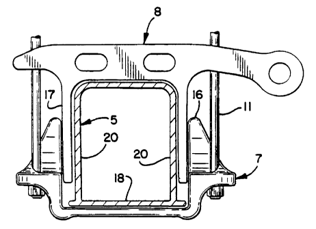
retorquing of the clamping bolts. The system as shown in figure 10 uses
interfitting bottom (7) and top (8) axle housing wraps.
The bottom axle wrap (7) has upwardly extending sides (16) engaging opposite
sides of the axle housing either directly or against
interfitting downward extensions (17) on the top axle housing wrap (8).
Vertical clamping bolts (11) cause the upwardly extending
sides (16) on the bottom wrap (7) to press inwardly against the sides of the
axle housing (5).


French Abstract

L'invention concerne des suspensions de camions et semi-remorques ainsi que des systèmes permettant de fixer un carter de pont à un élément et un ressort de support de suspension combinés de façon que le carter de pont soit fixé et comprimé uniformément sur les quatre côtés, le carter de pont ne risquant sensiblement pas de s'affaisser ou de se déformer, ce qui nécessiterait de fréquents resserrages des boulons de serrage. Le système, tel qu'illustré dans la figure 10, utilise des enveloppes inférieure (7) et supérieure (8) d'ajustement du carter de pont. L'enveloppe inférieure (7) présente des côtés (16) s'étendant vers le haut en prise avec les côtés opposés du carter de pont soit directement, soit contre les extensions d'ajustement vers le bas (17) sur l'enveloppe supérieure (8) du carter de pont. Grâce à des boulons de serrage verticaux (11), les côtés (16) s'étendant vers le haut sur l'enveloppe inférieure (7) poussent vers l'intérieur contre les côtés du carter de pont (5).

Claims

Note: Claims are shown in the official language in which they were submitted.


What Is Claimed Is:


1. In an axle suspension, duplicated on each side of a vehicle and having
at least one axle and including a combination support member and spring, a
system
for clamping said axle adjacent one end of said combination support member and

spring comprising,
a bottom axle wrap on which the bottom side of said axle is seated,
a top axle wrap seated on the top side of said axle and engaging the underside

of said combination support member and spring,
a clamping plate seated on the top of said combination support member and
spring and having at least one bolt hole extending through it,
a plurality of bolts clamping together an assembly comprising in upward
vertical orientation, said bottom axle wrap, said axle, said top axle wrap,
said
combination support member and spring and said clamping plate,
at least one of said plurality of bolts being secured to said clamping plate
and
extending into said at least one bolt hole of said clamping plate, and
said bottom axle wrap having upwardly extending sides which act against
opposite sides of said axle, and said bolts extending between said bottom axle
wrap
and said clamping plate and spaced outwardly of said axle whereby tensioning
of said
bolts applies compressive forces against all four sides of said axle.


2. In an axle suspension, duplicated on each side of a vehicle and having
at least one axle and including a combination support member and spring, a
system
for clamping said axle adjacent one end of said combination support member and

spring comprising,
a bottom axle wrap on which the bottom side of said axle is seated,
a top axle wrap seated on the top side of said axle and engaging the underside

of said combination support member and spring,
a clamping plate seated on the top of said combination support member and
spring,

a plurality of bolts clamping together an assembly comprising in upward
vertical orientation, said bottom axle wrap, said axle, said top axle wrap,
said
combination support member and spring and said clamping plate,
said bottom axle wrap having upwardly extending sides which act against
opposite sides of said axle, and said bolts extending between said bottom axle
wrap


6


and said clamping plate and spaced outwardly of said axle whereby tensioning
of said
bolts applies compressive forces against all four sides of said axle, and
said top axle wrap having downward extensions which embrace opposite sides
of said axle and interfit between said axle and said upwardly extending sides
on said
bottom axle wrap.


3. In the system for clamping of claim 2 the tightening of said bolts
causing said upwardly extending sides to tilt inwardly and cause said downward

extensions to bear against opposite sides of the axle whereby said axle is
embraced on
all four sides, on the bottom by said bottom axle wrap, on the top by said top
axle
wrap, and opposite sides by said downward extensions and said upwardly
extending
sides.


4. In an axle suspension, duplicated on each side of a vehicle and having
at least one axle and including a combination support member and spring, a
system
for clamping said axle adjacent one end of said combination support member and

spring comprising,
a first axle wrap positioned on one side of said axle,

a second axle wrap positioned on another side of said axle located vertically
opposite said one side of said axle, and said second axle wrap engaging the
combination support member and spring on one side thereof,
a clamping plate positioned on an opposite side of said combination support
member and spring and having at least one bolt hole extending through it,
a plurality of bolts clamping together an assembly comprising in vertical
orientation, said first axle wrap, said axle, said second axle wrap, said
combination
support member and spring and said clamping plate,

at least one of said plurality of bolts being secured to said clamping plate
and
extending into said at least one bolt hole of said clamping plate, and
said first axle wrap having extending sides which act against longitudinally
opposite sides of said axle, and said bolts extending between said first axle
wrap and
said clamping plate and spaced outwardly of said axle whereby tensioning of
said
bolts applies compressive forces against all four sides of said axle.


5. In an axle suspension, duplicated on each side of a vehicle and having
at least one axle and including a combination support member and spring, a
system


7


for clamping said axle adjacent one end of said combination support member and

spring comprising,
a first axle wrap positioned on one side of said axle,
a second axle wrap positioned on another side of said axle located vertically
opposite said one side of said axle, and said second axle wrap engaging the
combination support member and spring on one side thereof,

a clamping plate positioned on an opposite side of said combination support
member and spring,
a plurality of bolts clamping together an assembly comprising in vertical
orientation, in order, said first axle wrap, said axle, said second axle wrap,
said
combination support member and spring and said clamping plate,
said first axle wrap having extending sides which act against longitudinally
opposite sides of said axle, and said bolts extending between said first axle
wrap and
said clamping plate and spaced outwardly of said axle whereby tensioning of
said
bolts applies compressive forces against all four sides of said axle, and
said second axle wrap having extensions which embrace said longitudinally
opposite sides of said axle and interfit between said axle and said extending
sides of
said first axle wrap.


6. In the system for clamping of claim 5 the tightening of said bolts
causing said extending sides of said first axle wrap to tilt inwardly and
cause said
extensions of said second axle wrap to bear against said longitudinally
opposite sides
of said axle whereby said axle is embraced on all four sides.


8

Description

Note: Descriptions are shown in the official language in which they were submitted.


CA 02405891 2002-10-15

WO 01/79010 PCT[USOI/40544
AXLE CLAMP ATTACHMENT SYSTEM

Ashley T. Dudding and Lawrence Miller
SPECIFICATION
Brief Description of the Invention
Field of the Invention
The present invention relates generally to suspensions
for trucks and trailers and in particular to innovations and
improvements in the system for clamping an axle housing to a
combination suspension support member and spring in such a
way that the axle housing is clamped and compressed
uniformly on all four sides whereby there is no appreciable
tendency for the axle housing to collapse or become deformed
so as to require frequent re-torquing of the clamping bolts.
Discussion
In truck and trailer suspensions the opposite ends of
the axle housings must be securely clamped to a support such
as a combination suspension support and spring. Heretofore,
various clamping systems have been used, usually resulting
in compressive forces being applied to the top and bottom c=
an axle housing with the clamp bolt load being very high,
typically in the range of 30,000 to 50,000 pounds per bolt.
Usually four bolts are used together at each clamping site
making the total load there in the range of 120,000 to
200,000 pounds. Clamp bolt loads in this range generate a
very high bending load on the bottom plate which engages t!-:e
underside of an axle housing thereby requiring the plate tc
be very thick and heavy in order to sustain the load to
which it is subjected. The thickness takes up ground
clearance and the bending load produces a"spring" effect
causing flexing of the bottom plate, making it very
difficult to obtain a secure clamping joint. Further, tne-
has been no convenient method to positively locate the

1


CA 02405891 2002-10-15

WO 01/79010 PCT/USOl/40544
bottom plate relative to the axle housing. This results _-
the bolts not being perpendicular to the axle housing whic~,
in turn, detracts from the security of the joint.
With the clamping forces in prior clamping systems
being essentially confined to the bottom and top plates,
there was a tendency for the sidewalls of the axle housing
to deform or collapse allowing the clamping bolts to loosen
whereupon the bolts had to be re-tightened or re-torqued
after relatively short periods of service.
According to the present invention novel bottom axle
housing wraps and top axle housing wraps are provided whic:
act to apply the clamping forces substantially uniformly tc
all four sides of an axle housing thereby eliminating any
appreciable tendency for the axle housing to be deformed or
for the clamping *joint to become loose.
The invention involves the use of novel bottom and tcc
axle housing wraps. The bottom axle housing wraps have
upwardly extending fingers or sides the inner surfaces of
which bear against the opposite sides of the axle housing
either directly or against interfitting downward extensions
on the top axle housing wrap. The vertical clamping bolts
extend between the top and bottom axle housing wraps and
clamping plate on a leaf spring or other support with the
bolts being spaced from the sides of the axle housing so as
to allow the fingers or upwardly extending sides on the
bottom wrap to press inwardly against the sides of the axle
housing.
In a preferred embodiment, the top axle housing wrap
has depending or downwardly extending sides which engage t~e
sidewalls of the axle housing and telescope into the
upwardly extending sides or fingers on the bottom axle
housing wrap.
For a more complete understanding of the nature and
scope of the invention reference may be had to the follovr; ~
detailed description of a presently preferred embodiment
taken in connection with the accompanying drawings, where:-:
2


CA 02405891 2007-10-23

Brief DescriptiQn of the Drawings
rIG. I is afragmenca=! perspective view of a syste-i
for clamping an end of ar. axle housing to a combination
suFport member and spri.~.g -Z accordance with the p:esent
_~vention;
FIG. 2 is a fragmentary perspective view showing the
bottom axle housing wrap and top axle housing wrap of FIG,
y
in izterfitting relationship on an axle housing;
FIG. 3 is a top plan view of the bottom axle hous_r.g
wrap of FIGS. 1 and 2;
FIG. 4 is a side elevational view taken on lir.e 4-4 c!
FIG. 3;
FIG. 5 is a side elevacional view taken on line 5-5 of
FIG. 3;
FIG. 6 is a sectional vwew taken on line 6-6 of FIC.
FIG. 7 is a sectional view taken on lzne 7-7 of FIG. 3;
FIG. 8 is a plan view of the bottom side of the bottom
axle housing wrap of FIG. 3;
FIG. 9 is a sectional view taken on line 9-9 of FIG. 3;
2Q FIG. 10 is an end alevational view taken an line 10-10
of FIG. 2; and
FIG. 11 is a side elevational view of the top axle ~wrap
of FIGS. 1 and 2.
Referring to FIGS. I ar.d 2, a fabricated axle housing
z5 =s indicated generally at 5 which is the axle hvusing for
the front axle of a truck but which is representative of ar_=;
axle housing, front or rear, of a truck. The system for
clamping the axle housing 5 to a combination suspension
support member and leaf sgring ir,dicated generally at 6
0 ccmprises a bottom axle housing wrap indicated generally at
7, a ton axle housing wrap indicated generally at 8, a too
clamping plate or top spri:,g pad indicated generally at
and four clamping bolts i:dicated generally at 11-11. :he
spring 6 may correspond to che tapered convolute leaf sp;_,ca
35 shown and described in U.S. patent No. 5,938,221.

The bottom axle hous=:.g Nran 11 is shown in greater
3


CA 02405891 2002-10-15

WO 01/79010 PCT/USO1/40544
detail in FIGS. 3-10 to which reference is now made. The
bottcm axle wrap 11 may be either a casting or a forging
with relatively wide openings in the interest cf weight and
cost reduction. It has two narrow side members 12-12 and a
wider central member 13. The opposite ends of the members
12 and 13 are turned up and integrally joined by end cross
members 14-14 in each of which two bolt holes 15-15 for the
bolts 11 are located. Integrally formed on each of the end
cross members 14 is an upwardly extending side or extension
16.
The bottom axle housing wrap 11 is designed to
telescopically mate with a top axle housing wrap 8 (FIG. 11)
in the manner shown in FIG. 10. The top axle wrap 8 has a
width approximately equal to the distance between each pair
of bolts 11 and the width of the combination suspension
member and spring 6 so as to permit the assembly shown in
FIG. 1. The top axle housing 8 has a pair of downwardly
extending side members 17 which fit over the opposite sides
of the axle housing 5 and between the upward extensions 16
on the bottom axle housing wrap 7 as shown in FIG. 10. As
will be seen from FIG. 10 the bolts 11 are spaced an
appreciable distance from the downwardly extending sides 17
of the top axle housing wrap 8 as well as from the opposite
sides of the bottom wall 18 of the axle housing 5. As a
result of this spacing, when the bolts 11 are tightened and
placed under tension the opposite bottom edges of the axle
housing 5 will act as fulcrums and allow the extensions 16
on the bottom axle housing wrap 7 to be tilted inwardly a
small but appreciable amount against the downwardly
extending sides 17 on the top axle wrap 8. This in turn
will cause the downward extensions 17 to press against the
opposite sides 20-20 of the axle housing 5. The result will
be in the assembly shown in FIG. 1 that compressive forces
will be uniformly applied to all four sides of the axle
housing 5 whereby the tendency of the axle housing 5 to
deform or collapse will be substantially eliminated.
If desired, the bottom and top axle housing
4


CA 02405891 2002-10-15

WO 01/79010 PCT/US01/40544
wraps may be provided with liners (not shown) which act to
improve the sec,.:rity of the clamped assembly.


Representative Drawing
A single figure which represents the drawing illustrating the invention.
Administrative Status

For a clearer understanding of the status of the application/patent presented on this page, the site Disclaimer , as well as the definitions for Patent , Administrative Status , Maintenance Fee  and Payment History  should be consulted.

Administrative Status

Title Date
Forecasted Issue Date 2008-11-25
(86) PCT Filing Date 2001-04-18
(87) PCT Publication Date 2001-10-25
(85) National Entry 2002-10-15
Examination Requested 2006-04-11
(45) Issued 2008-11-25
Expired 2021-04-19

Abandonment History

There is no abandonment history.

Payment History

Fee Type Anniversary Year Due Date Amount Paid Paid Date
Application Fee $300.00 2002-10-15
Registration of a document - section 124 $100.00 2003-02-19
Maintenance Fee - Application - New Act 2 2003-04-22 $100.00 2003-03-26
Maintenance Fee - Application - New Act 3 2004-04-19 $100.00 2004-04-07
Maintenance Fee - Application - New Act 4 2005-04-18 $100.00 2005-03-17
Registration of a document - section 124 $100.00 2005-08-26
Maintenance Fee - Application - New Act 5 2006-04-18 $200.00 2006-03-14
Request for Examination $800.00 2006-04-11
Maintenance Fee - Application - New Act 6 2007-04-18 $200.00 2007-04-04
Maintenance Fee - Application - New Act 7 2008-04-18 $200.00 2008-04-18
Final Fee $300.00 2008-09-03
Maintenance Fee - Patent - New Act 8 2009-04-20 $200.00 2009-03-30
Maintenance Fee - Patent - New Act 9 2010-04-19 $200.00 2010-03-30
Maintenance Fee - Patent - New Act 10 2011-04-18 $250.00 2011-03-30
Maintenance Fee - Patent - New Act 11 2012-04-18 $250.00 2012-03-30
Maintenance Fee - Patent - New Act 12 2013-04-18 $250.00 2013-04-01
Maintenance Fee - Patent - New Act 13 2014-04-22 $250.00 2014-04-14
Maintenance Fee - Patent - New Act 14 2015-04-20 $250.00 2015-04-13
Maintenance Fee - Patent - New Act 15 2016-04-18 $450.00 2016-04-11
Maintenance Fee - Patent - New Act 16 2017-04-18 $450.00 2017-04-17
Maintenance Fee - Patent - New Act 17 2018-04-18 $450.00 2018-04-16
Maintenance Fee - Patent - New Act 18 2019-04-18 $450.00 2019-04-12
Maintenance Fee - Patent - New Act 19 2020-04-20 $450.00 2020-04-14
Owners on Record

Note: Records showing the ownership history in alphabetical order.

Current Owners on Record
HENDRICKSON INTERNATIONAL CORPORATION
Past Owners on Record
DUDDING, ASHLEY T.
MILLER, LAWRENCE
THE BOLER COMPANY.
Past Owners that do not appear in the "Owners on Record" listing will appear in other documentation within the application.
Documents

To view selected files, please enter reCAPTCHA code :


To view images, click a link in the Document Description column. To download the documents, select one or more checkboxes in the first column and then click the "Download Selected in PDF format (Zip Archive)" or the "Download Selected as Single PDF" button.

List of published and non-published patent-specific documents on the CPD .

If you have any difficulty accessing content, you can call the Client Service Centre at 1-866-997-1936 or send them an e-mail at CIPO Client Service Centre.


Document
Description 
Date
(yyyy-mm-dd) 
Number of pages   Size of Image (KB) 
Claims 2002-10-15 2 47
Representative Drawing 2002-10-15 1 9
Cover Page 2003-01-29 1 43
Abstract 2002-10-15 2 71
Drawings 2002-10-15 3 79
Description 2002-10-15 5 181
Description 2007-10-23 5 177
Claims 2007-10-23 3 145
Representative Drawing 2008-11-12 1 12
Cover Page 2008-11-12 2 50
Prosecution-Amendment 2006-04-11 1 47
PCT 2002-10-15 2 83
Assignment 2002-10-15 2 83
Correspondence 2003-01-27 1 24
Assignment 2003-02-19 6 306
PCT 2002-10-16 5 254
Assignment 2005-08-26 7 338
Assignment 2005-11-09 2 94
Prosecution-Amendment 2007-04-25 2 47
Prosecution-Amendment 2007-10-23 8 345
Correspondence 2008-09-03 1 43
Fees 2008-04-18 1 41