Language selection

Search

Patent 2409458 Summary

Third-party information liability

Some of the information on this Web page has been provided by external sources. The Government of Canada is not responsible for the accuracy, reliability or currency of the information supplied by external sources. Users wishing to rely upon this information should consult directly with the source of the information. Content provided by external sources is not subject to official languages, privacy and accessibility requirements.

Claims and Abstract availability

Any discrepancies in the text and image of the Claims and Abstract are due to differing posting times. Text of the Claims and Abstract are posted:

  • At the time the application is open to public inspection;
  • At the time of issue of the patent (grant).
(12) Patent: (11) CA 2409458
(54) English Title: STRAP HOLDING DEVICE
(54) French Title: DISPOSITIF DE FIXATION DE CHAPE DE FEUILLARD DE CERCLAGE
Status: Deemed expired
Bibliographic Data
(51) International Patent Classification (IPC):
  • E04C 5/16 (2006.01)
  • E04B 7/02 (2006.01)
  • E04C 3/02 (2006.01)
  • E04B 1/26 (2006.01)
(72) Inventors :
  • CRAWFORD, MARK G. (United States of America)
  • SHAMROUKH, LOUAY A. (United States of America)
(73) Owners :
  • SIMPSON STRONG-TIE COMPANY, INC. (United States of America)
(71) Applicants :
  • SIMPSON STRONG-TIE COMPANY, INC. (United States of America)
(74) Agent: RICHES, MCKENZIE & HERBERT LLP
(74) Associate agent:
(45) Issued: 2009-05-26
(22) Filed Date: 2002-10-22
(41) Open to Public Inspection: 2003-04-30
Examination requested: 2006-07-20
Availability of licence: N/A
(25) Language of filing: English

Patent Cooperation Treaty (PCT): No

(30) Application Priority Data:
Application No. Country/Territory Date
10/000,678 United States of America 2001-10-30

Abstracts

English Abstract


The present invention provides a connection having a plurality of parallel
structural members. The structural members are bridged by strap member,
preferably light gauge steel. The end of the strap member is held in place by
an overlapping strap holder. Fasteners hold the strap holder and the strap to
the underlying structural member, with at least one passing through only the
strap holder into the first side of the the first structural member.


Claims

Note: Claims are shown in the official language in which they were submitted.


6

We claim:


1. A connection comprising:
i. a plurality of substantially parallel structural members;
ii. a first structural member having a first side;
iii. a strap member having an upper surface, a lower surface, a first side
edge, a second side edge, and a first end edge;
iv. a strap holder having an upper face and a lower face, said lower face
being dimensioned to interface with said first side of said first structural
member
and attached only to said first structural member of said plurality of
structural
members; and
v. a plurality of fasteners; wherein
vi. said lower surface of said strap member interfaces with said first
side of said first structural member;
vii. said lower face of said strap holder interfaces with said upper
surface of said strap member, extending beyond said first side edge
to interface with said first side of said first structural member;
viii. at least one of said plurality of fasteners passes through both said
strap holder and said strap member and into said first side of said first
structural member;
ix. at least one of said plurality of fasteners passes through only said
strap holder into said first side of said first structural member; and
x. said strap member crosses over said plurality of substantially
parallel structural members;
wherein said first structural member further comprises a second side and a
first juncture between said first side and said second side and wherein said
strap
member is bent over said first juncture and interfaces with said second side;
and
wherein said strap holder additionally comprises a first transition line and a

second transition line, said first transition line and said second transition
line
dividing said upper face and said lower face into a first attachment portion,
a
second attachment portion, and a first securement portion between said first
transition line and said second transition line, and wherein said first
securement


7

portion is dimensioned to closely interface with said upper surface of said
strap
member, said first transition line being closely parallel to said first side
edge of said
strap and said second transition fine being closely parallel to said second
side edge
of said strap.


2. The connection of claim 1, wherein one or more of said plurality of
fasteners
passes through said first attachment portion into said first side of said
first structural
member, one or more of said plurality of fasteners passes through said second
attachment portion into said first side of said first structural member, and
one or
more of said plurality of fasteners passes through said first securement
portion,
through said strap member, and into said first side of said first structural
member.

3. The connection of claim 2, wherein said plurality of substantially parallel

structural members and said first structural member are the top chords of roof

trusses.


4. The connection of claim 3, wherein said top chords of roof trusses are made

of wood.


5. The connection of claim 4, wherein said fasteners are nails.


6. The connection of claim 5, wherein said strap holder is formed with
fastener
openings.


7. The connection of claim 6, wherein said strap is formed with fastener
openings.


8. The connection of claim 2, wherein said plurality of substantially parallel

structural members and said first structural member are floor beams.


9. The connection of claim 8, wherein said floor beams are made of wood.


8

10. The connection of claim 9, wherein said fasteners are nails.


11. The connection of claim 10, wherein said strap holder is formed with
fastener
openings.


12. The connection of claim 11, wherein said strap is formed with fastener
openings.


13. The connection of claim 2, wherein said plurality of substantially
parallel
structural members and said first structural member are wall studs.


14. The connection of claim 13, wherein said wall studs are made of wood.

15. The connection of claim 14, wherein said fasteners are nails.


16. The connection of claim 15, wherein said strap holder is formed with
fastener
openings.


17. The connection of claim 16, wherein said strap is formed with fastener
openings.


18. A connection comprising:
a. a plurality of substantially parallel structural members;
b. a first structural member comprising a first side, a second side and a
first
juncture between said first side and said second side;
c. a strap member having an upper surface, a lower surface, a first side
edge, a second side edge, and a first end edge;
d. a strap holder having an upper face and a lower face, said lower face
being dimensioned to interface with said first side of said first structural
member
and attached only to said first structural member of said plurality of
structural
members; and
e. a plurality of fasteners; wherein


9

i. said lower surface of said strap member interfaces with said first
side of said first structural member;
ii. said lower face of said strap holder interfaces with said upper
surface of said strap member, extending beyond said first side edge to
interface with said first side of said first structural member;
iii. at least one of said plurality of fasteners passes through both said
strap holder and said strap member and into said first side of said first
structural member;
iv. at least one of said plurality of fasteners passes through only said
strap holder into said first side of said first structural member; and
v. said strap member crosses over said plurality of substantially
parallel structural members and, in substantially the same plane, said
second side of said first structural member, interfacing with said second side

of said first structural member, and said strap member is bent over said first

juncture.


19. The connection of claim 18, wherein said strap holder additionally
comprises
a first transition line and a second transition line, said first transition
line and said
second transition line dividing said upper face and said lower face into a
first
attachment portion, a second attachment portion, and a first securement
portion
between said first transition line and said second transition line, and
wherein said
first securement portion is dimensioned to closely interface with said upper
surface
of said strap member, said first transition line being closely parallel to
said first side
edge of said strap and said second transition line being closely parallel to
said
second side edge of said strap.


20. The connection of claim 19, wherein one or more of said plurality of
fasteners passes through said first attachment portion into said first side of
said first
structural member, one or more of said plurality of fasteners passes through
said
second attachment portion into said first side of said first structural
member, and
one or more of said plurality of fasteners passes through said first
securement
portion, through said strap member, and into said first side of said first
structural


10


member.


21. The connection of claim 20, wherein said plurality of substantially
parallel
structural members and said first structural member are the top chords of roof

trusses.


22. The connection of claim 21, wherein said top chords of roof trusses are
made of wood.


23. The connection of claim 22, wherein said fasteners are nails.


24. The connection of claim 23, wherein said strap holder is formed with
fastener
openings.


25. The connection of claim 24, wherein said strap is formed with fastener
openings.


26. The connection of claim 20, wherein said plurality of substantially
parallel
structural members and said first structural member are floor beams.


27. The connection of claim 26, wherein said floor beams are made of wood.

28. The connection of claim 27, wherein said fasteners are nails.


29. The connection of claim 28, wherein said strap holder is formed with
fastener
openings.


30. The connection of claim 29, wherein said strap is formed with fastener
openings.


31. The connection of claim 30, wherein said plurality of substantially
parallel
structural members and said first structural member are wall studs.


11


32. The connection of claim 31, wherein said wall studs are made of wood.

33. The connection of claim 32, wherein said fasteners are nails.


34. The connection of claim 33, wherein said strap holder is formed with
fastener
openings.


35. The connection of claim 34, wherein said strap is formed with fastener
openings.


Description

Note: Descriptions are shown in the official language in which they were submitted.


CA 02409458 2006-09-14

1
STRAP HOLDING DEVICE

BACKGROUND OF THE INVENTION

The present invention relates to a connection in which a strap bridges a
plurality of
substantially parallel structural members and is secured by a strap holder,
especially where an elongate utility strap is used, typically in pairs forming
X
bracing, to reinforce roof trusses against forces acting along the length of
the roof.
Single diagonal braces of this general type are also commonly used in walls in
light
wood frame construction, and might also be used to brace floor beams or other
series of parallel structural members.

SUMMARY OF THE INVENTION

It is an object of the present invention to provide a secure connection
between an
elongated strap member and a structural member. The present invention improves
on the prior art of simply nailing through the strap and into the structural
member
beneath it. The present invention provides a connection having a plurality of
parallel structural members. The structural members are bridged by strap
member,
preferably light gauge steel. The end of the strap member is held in place by
an
overlapping strap holder. Fasteners hold the strap holder and the strap to the
underlying structural member, with at least one passing through only the strap
holder into the first side of the the first structural member.

In one aspect, the present invention resides in a connection comprising: a. a
plurality of substantially parallel structural members; b. a first structural
member
comprising a first side, a second side and a first juncture between said first
side and
said second side; c. a strap member having an upper surface, a lower surface,
a
first side edge, a second side edge, and a first end edge; d. a strap holder
having
an upper face and a lower face, said lower face being dimensioned to interface
with
said first side of said first structural member and attached only to said
first structural
member of said plurality of structural members; and e. a plurality of
fasteners;


CA 02409458 2008-10-02

la
wherein i. said lower surface of said strap member interfaces with said first
side of
said first structural member; ii. said lower face of said strap holder
interfaces with
said upper surface of said strap member, extending beyond said first side edge
to
interface with said first side of said first structural member; iii. at least
one of said
plurality of fasteners passes through both said strap holder and said strap
member
and into said first side of said first structural member; iv. at least one of
said
plurality of fasteners passes through only said strap holder into said first
side of
said first structural member; and v. said strap member crosses over said
plurality of
substantially parallel structural members and, in substantially the same
plane, said
second side of said first structural member, interfacing with said second side
of said
first structural member, and said strap member is bent over said first
juncture.

In another aspect, the present invention resides in a connection comprising:
i. a
plurality of substantially parallel structural members; ii. a first structural
member
having a first side; iii. a strap member having an upper surface, a lower
surface, a
first side edge, a second side edge, and a first end edge; iv. a strap holder
having
an upper face and a lower face, said lower face being dimensioned to interface
with
said first side of said first structural member and attached only to said
first structural
member of said plurality of structural members; and v. a plurality of
fasteners;
wherein vi. said lower surface of said strap member interfaces with said first
side of
said first structural member; vii. said lower face of said strap holder
interfaces with
said upper surface of said strap member, extending beyond said first side edge
to
interface with said first side of said first structural member; viii. at least
one of said
plurality of fasteners passes through both said strap holder and said strap
member
and into said first side of said first structural member; ix. at least one of
said
plurality of fasteners passes through only said strap holder into said first
side of
said first structural member; and x. said strap member crosses over said
plurality of
substantially parallel structural members; wherein said first structural
member
further comprises a second side and a first juncture between said first side
and said
second side and wherein said strap member is bent over said first juncture and
interfaces with said second side; and wherein said strap holder additionally
comprises a first transition line and a second transition line, said first
transition line


CA 02409458 2008-10-02

lb
and said second transition line dividing said upper face and said lower face
into a
first attachment portion, a second attachment portion, and a first securement
portion between said first transition line and said second transition line,
and
wherein said first securement portion is dimensioned to closely interface with
said
upper surface of said strap member, said first transition line being closely
parallel to
said first side edge of said strap and said second transition fine being
closely
parallel to said second side edge of said strap.

BRIEF DESCRIPTION OF THE DRAWINGS

FIG. I is an isometric view of a roof, showing three sections of roof trusses
connected by strap members arranged in X patterns.


CA 02409458 2002-10-22

2
FIG. 2 is an isometric view of a plurality of roof trusses, joined by
perpendicular bracing and by connections of the present invention.
FIG. 3 is a side elevation view of the preferred embodiment of the strap
holder of the present invention.
FIG. 4 is a top plan view of the preferred embodiment of the strap holder of
the present invention.
FIG. 5 is a side elevation view of the preferred embodiment of the strap
holder of the present invention, perpendicular to the view of FIG. 3.
FIG. 6 is a bottom plan view of the preferred embodiment of the strap holder
of the present invention.
FIG. 7 is a side elevation view of a roof truss showing a plurality of
connections of the present invention, in particular the interface of first
structural member, strap and strap holder.
FIG. 8 is a side elevation view of the strap holder, strap member and first
structural member of the present invention, connected by fasteners.
FIG. 9 is an isometric view of an alternate preferred embodiment of the
present invention, in which the plurality of substantially parallel structural
members are wall studs.
FIG. 10 is an an isometric view of a second alternate preferred embodiment
of the present invention, in which the plurality of substantially parallel
structural members are floor joists.

DETAILED DESCRIPTION OF THE PREFERRED EMBODIMENT

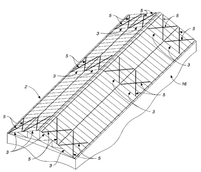
As best seen in FIG. 2, the preferred form of the present invention is a
connection 1 comprising a plurality of substantially parallel structural
members 2, a first structural member 3 having a first side 4, a strap member
5 having an upper surface 6, a lower surface 7, a first side edge 8, a second
side edge 9, and a first end edge 10, a strap holder 12 having an upper face
13 and a lower face 14, the lower face 14 being dimensioned to interface

..,.__.._.. .. _ . __ _....._...
_ _...._ . . __... ..,...___..,._..._.__._ _ _ _._.____.._..,~.


CA 02409458 2002-10-22

3
with the first side 4 of the first structural member 3 and attached only to
the
first structural member 3 of the plurality of structural members 2, and a
plurality of fasteners 15. The lower surface 7 of the strap member 5
interfaces with the first side 4 of the first structural member 3, the lower
face 14 of the strap holder 12 interfaces with the upper surface 6 of the
strap member 5, extending beyond the first side edge 8 to interface with the
first side 4 of the first structural member 3, at least one of the plurality
of
fasteners 15 passes through both the strap holder 12 and the strap member
5 and into the first side 4 of the first structural member 3, at least one of
the
plurality of fasteners 15 passes through only the strap holder 12 into the
first
side 4 of the first structural member 3, and the strap member 5 crosses over
the plurality of substantiaily parallel structural members 2. As shown in FIG.
2, in the preferred embodiment of the present invention, the substantially
parallel structural members 2 are the top members of roof trusses 11. The
connection 1 of the present invention is paired to create X bracing that
reinforces the roof 16 against forces acting primarily along the length of the
roof 16, which is otherwise relatively rigid where it joins the wall below,
which is typically reinforced by sheathing against shear forces acting along
the length of the wall. As shown in FIG. 1, a number of areas of the roof 16
are reinforced with X bracing, which is often required by building codes.
As best shown in FIG. 7 and in detail in FIG. 8 in the preferred embodiment
the first structural member 3 further comprises a second side 17 and a first
juncture 18 between the first side 4 and the second side 17. The strap
member 5 is bent over the first juncture 18 and interfaces with the second
side 17.

As best shown in FIG. 3, FIG. 4, FIG. 5, and FIG. 6, in the preferred
embodiment the strap holder 12 additionally comprises a first transition line
19 and a second transition line 20, the first transition line 19 and the
second

, ._ -=- .._. __. .


CA 02409458 2002-10-22

4
transition line 20 dividing the upper face 13 and the lower face 14 into a
first
attachment portion 21, a second attachment portion 22, and a first
securement portion 23 between the first transition line 19 and the second
transition line 20, and wherein the first securement portion 23 is dimensioned
to closely interface with the upper surface 6 of the strap member 5, the first
transition line 19 closely parallel to the first side edge 8 and the second
transition line 20 closely parallel to the second side edge 9. In the
preferred
embodiment, the first transition line 19 and the second transition line 20 are
double bends that create a raised securement portion 23 that bisects the
middle of the strap holder 12.

As best shown in FIG. 7 and FIG. 8, in the preferred embodiment one or
more of the plurality of fasteners 15 passes through the first attachment
portion 21 into the first side 4 of the first structural member 3, one or more
of the plurality of fasteners 15 passes through the second attachment portion
22 into the first side 4 of the first structural member 3, and one or more of
the plurality of fasteners 15 passes through the first securement portion 23,
through the strap member 5, and into the first side 4 of the first structural
member 3.
As shown in FIG. 2, in the preferred embodiment, the plurality of
substantially parallel structural members 2 and the first structural member 3
are the top chords of roof trusses 11 and the top chords of roof trusses 25
are made of wood. As shown in FIG. 10, in an alternate preferred
embodiment, the plurality of substantially parallel structural members 2 and
the first structural member 3 are floor beams, and the floor beams are made
of wood. As shown in FIG. 9, in another alternate preferred embodiment, the
plurality of substantially parallel structural members 2 and the first
structural
member 3 are wall studs. Notwithstanding the above, the substantially
parallel structural members 2 may be any such series of structural members,


CA 02409458 2002-10-22

and may made of any material, such as steel. In the preferred embodiment,
the fasteners 15 are nails, although they may be screws, bolts or any other
type of pin-like fastener.

5 In the preferred embodiment, the strap member 5 and strap holder 12 are
both formed from light gauge steel, but either or both may be formed from
other metals or plastics, or any other material that may be formed into the
necessary shapes.

In the preferred embodiment, the strap holder 12 is formed with a plurality of
fastener openings 24 and the strap member 5 is also formed with a plurality
of fastener openings 25.

Representative Drawing
A single figure which represents the drawing illustrating the invention.
Administrative Status

For a clearer understanding of the status of the application/patent presented on this page, the site Disclaimer , as well as the definitions for Patent , Administrative Status , Maintenance Fee  and Payment History  should be consulted.

Administrative Status

Title Date
Forecasted Issue Date 2009-05-26
(22) Filed 2002-10-22
(41) Open to Public Inspection 2003-04-30
Examination Requested 2006-07-20
(45) Issued 2009-05-26
Deemed Expired 2011-10-24

Abandonment History

There is no abandonment history.

Payment History

Fee Type Anniversary Year Due Date Amount Paid Paid Date
Registration of a document - section 124 $100.00 2002-10-22
Application Fee $300.00 2002-10-22
Maintenance Fee - Application - New Act 2 2004-10-22 $100.00 2004-07-19
Maintenance Fee - Application - New Act 3 2005-10-24 $100.00 2005-07-14
Request for Examination $800.00 2006-07-20
Maintenance Fee - Application - New Act 4 2006-10-23 $100.00 2006-07-21
Maintenance Fee - Application - New Act 5 2007-10-22 $200.00 2007-07-11
Maintenance Fee - Application - New Act 6 2008-10-22 $200.00 2008-09-16
Final Fee $300.00 2009-03-10
Maintenance Fee - Patent - New Act 7 2009-10-22 $200.00 2009-10-22
Owners on Record

Note: Records showing the ownership history in alphabetical order.

Current Owners on Record
SIMPSON STRONG-TIE COMPANY, INC.
Past Owners on Record
CRAWFORD, MARK G.
SHAMROUKH, LOUAY A.
Past Owners that do not appear in the "Owners on Record" listing will appear in other documentation within the application.
Documents

To view selected files, please enter reCAPTCHA code :


To view images, click a link in the Document Description column. To download the documents, select one or more checkboxes in the first column and then click the "Download Selected in PDF format (Zip Archive)" or the "Download Selected as Single PDF" button.

List of published and non-published patent-specific documents on the CPD .

If you have any difficulty accessing content, you can call the Client Service Centre at 1-866-997-1936 or send them an e-mail at CIPO Client Service Centre.


Document
Description 
Date
(yyyy-mm-dd) 
Number of pages   Size of Image (KB) 
Abstract 2002-10-22 1 12
Description 2002-10-22 5 176
Claims 2002-10-22 4 95
Drawings 2002-10-22 6 178
Representative Drawing 2003-01-08 1 20
Cover Page 2003-04-04 1 45
Description 2006-09-14 6 216
Description 2008-10-02 7 270
Claims 2008-10-02 6 206
Representative Drawing 2009-05-05 1 22
Cover Page 2009-05-06 2 52
Assignment 2002-10-22 11 564
Fees 2004-07-19 1 35
Prosecution-Amendment 2006-07-20 1 42
Fees 2006-07-21 1 42
Fees 2005-07-14 1 32
Fees 2008-09-16 1 52
Prosecution-Amendment 2006-09-14 7 224
Fees 2007-07-11 1 44
Prosecution-Amendment 2008-04-30 2 76
Prosecution-Amendment 2008-10-02 11 389
Correspondence 2009-03-10 1 52
Fees 2009-10-22 1 51