Note: Descriptions are shown in the official language in which they were submitted.
CA 02414351 2002-12-24
Device for Injecting Bone Cement
The invention relates_to.a device fo.r.injecting bone.cement, containing a
guide wire and a cannula fitting snugly on the guide wire at least with the
inner
diameter of its front axial orifice.
Augmenting osteoporotic bones with injected bone cement for fracture
prophylaxis is already known. With the injection cannulae used so far with
axial exit aperture, the filling cannot be placed with the desired precision
in
many cases.
It is therefore an object of the invention to propose a device for injecting
io bone cement in which the discharge direction of the bone cement after
insertion
of the cannula is able to be guided into a particular area.
According to a first variant of the invention, this object is achieved in that
there are closing off means with which the front, axial orifice of the cannula
is
closable after removal of the guide wire and in that the cannula has a radial
aperture, for exit of the bone cement, near the front, axial orifice.
According to a special embodiment of this variant, the closing off means
is an inner cannula, closed on its front end, which inner cannula is
insertable in
the cannula in such a way that its front end closes the orifice of the cannula
tightly and has a radial aperture near its front, closed end.
According to another, especially preferred embodiment of the first
variant, the diameter of the front, axial orifice of the cannula is smaller
than the
inner diameter of the cannula and the closing off means is a stopper, the
largest diameter of which is larger than the diameter of the front, axial
orifice of
the cannula. When the orifice is closed off by the stopper, the entire inner
cross-section of the cannula is available for the passage of the bone cement
so
that in this embodiment the flow resistance for the bone cement is
considerably
less than with the previously mentioned embodiment.
According to a second variant of the invention, this object is achieved in
that an inner cannula is provided, closed at its front end, which has near the
front, closed end a radial aperture for exit of the bone cement and which fits
snugly in the front axial orifice of the cannula at least in a region close to
the
edge, remote from its front end, of the radial aperture, whereby, after
removal
CA 02414351 2007-08-14
2
of the guide wire, the inner cannula is insertable so far into the cannula
that its
radial aperture extends beyond the cannula.
So, the present invention as claimed hereafter is directed to a device for
injecting bone cement, comprising a guide wire and a first cannula fitting on
the
guide wire at least with an inner diameter of a front axial orifice of the
first
cannula, and closing off means with which the front axial orifice of the first
cannula is closable after removal of the guide wire, wherein the first cannula
has
a radial aperture, near the front axial orifice, for exit of the bone cement.
The invention is also directed to a device for injecting bone cement,
comprising
a guide wire, a first cannula fitting snugly on the guide wire at least with
an inner
diameter of a front axial orifice and an inner cannula having a first end that
is
closed, said inner cannula having near its front end, a radial aperture for
the exit
of the bone cement, and which, at least in a region near the edge remote from
its front end, a radial aperture that fits snugly in the front axial orifice
of the first
cannula, whereby, after the removal of the guide wire, the inner cannula is
insertable so far into the first cannula tYtat its radial aperture extends
beyond the
axial orifice of said first cannula.
Other embodiments of the invention will be explained in the following, by way
of
example, with reference to the attached drawings.
Figures 1 a to 1 d show a first embodiment example of a device according
to the invention with a cannula with radial aperture and an inner cannula,
which
likewise has a radial aperture,
Figures 2a to 2f show a second embodiment example of a device
according to the invention in which the cannula has a radial aperture and is
closed in the front by a body, and
Figures 3a to 3d show a third embodiment example of a device
according to the invention in which the cannula is surpassed in the front by
an
inner cannula with radial aperture.
CA 02414351 2007-08-14
2a
Figures 1 a, 2a and 3a each show a guide wire I which is pointed at its
front end 2. This front end 2 of the guide wire is driven forward, under X ray
control, into the bone up to some millimeters beyond the place at which the
bone cement is supposed to be injected. The guide wire typically has a
diameter of 2.5 mm and a length of 180 mm; the invention should not be
limited, however, to these dimensions. --
According to the embodiment example according to Figures 1 a to 1 d, a
cannula 3 is pushed over the guide wire. This cannula 3 has at its front end
an
orifice 4 with a sharply ground circumferential edge whose inner diameter fits
snugly over the guide wire. By means of this design, bone tissue is prevented
from getting into the interior of the cannula 3 during forwards pushing of the
cannula 3. Disposed on the rear (in the drawing left) end of the cannula is a
handle 6. The orifice 4 of the cannula can be slightly reduced and the
remaining inner diameter of the cannula can be 3.1 mm, for example. The
outer diameter of the cannula 3 can be 4 mm, for instance, and its length up
to
the handle 130 mm. Disposed in the cannula near the orifice 4 is a radial
aperture 5, the width of which is somewhat smaller than the inner diameter of
the carinula. The leiigth of this radiaf-apei'ture 5-i`sa-least the sa~e as
that bf
the aperture of the inner cannula 9 described further below. The handle is of
asymmetrical shape, for instance with a pointer-like form the tip of which is
CA 02414351 2002-12-24
3
aligned with the radial aperture 5, so that the surgeon knows the angular
position of the radial opening 5 at all times. The handle 6 has moreover a
recess 7 and a coupling 8, the function of which will be explained further
below.
Figure 1 c shows the cannula after the guide wire 1 has been pulled out.
An inner cannula 9 is inserted in the cannula 3 in Figure 1 d. The outer
diameter of this inner cannula is 3.0 mm, for instance, so that it can be
pushed
with play in the cannula 3. The inner diameter of the inner cannula can be 2.5
mm, for example. The front end 10 of the inner cannula is closed, and the
length of the inner cannula 9 as well as the outer diameter of the end 10 are
io dimensioned such that, with completely inserted inner cannula 9, the
orifice 4
of the cannula 3 is tightly sealed off. Located on the rear end of the inner
cannula 9 is a handle 12, which is also of asymmetrical design, like the
handle
6 of the cannula 3. The handle 12 has a protrusion 13, which forms together
with the recess 7 provided on the handle 6 a snap in locking device.
is Furthermore the inner cannula 9 has a radial aperture 11 in the vicinity of
the
end 10, which radial aperture coincides with the aperture 5 of the cannula,
with
the snap in locking device 7, 13 in snapped-in state. The width of the radial
aperture 11 of the inner cannula is somewhat less than its inner diameter, and
the length of the aperture 11 is dimensioned in such a way that the exit cross-
20 section of the aperture is at least just as large as the inner cross-
section of the
inner cannula 9. A coupling 14 provided on the handle 12 serves for
attachment of a bone cement source, for instance a needle.
A bone cement injection with this first embodiment of the device
according to the invention runs as follows. First, the guide wire 1 is driven
in,
25 as mentioned above. Then the cannula 3 is pushed over the guide wire 1 and
pressed in until its radial aperture 5 sits at the place where the injection
is
supposed to take place. Now the guide wire 1 is pulled out and the inner
cannula 9 is inserted in the cannula 3. After the two handles 6 and 12 are
locked together by means of the snap in locking device and a needle with bone
30 cement is connected with the coupling 14, the injection can begin. Thanks
to
the inventive design of the device, the physician is able to control the
discharge
-_----direction-of-thebane-cement--into-an-area-even-during the. injection..by-
turnirig
the two handles 6 and 12, locked together, and thus also the two radial
apertures 5 and 11, aligned with one another.
CA 02414351 2002-12-24
4
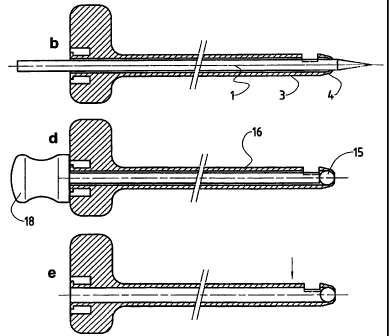
Figures 2a to 2f show a second embodiment of the device according to
the invention, a guide wire 1 with a tip 2 being shown once again n Figure 2a.
The cannula 3 has in principle the same construction as that in the first
embodiment example described above, which is why the same reference
numerals have been used here. One difference is that with the cannula
according to Figures 2b to 2e, the handle 17 is shaped differently from the
handle 7 according to Figures 1b to 1d, and.in particular has no recess 7
because in this second embodiment example there is no inner cannula 9. The
orifice 4 of the cannula 3 is closed off with a ball 15 in this embodiment,
which
io ball is pushed into its place with a plunger 16, as is shown.in Figure 2d,
after
pulling back of the guide wire 1. The plunger 16 has a support 18 and is so
long that the ball 15 sits at the right place when the support 18 abuts the
handle 17 of the cannula 3. In this embodiment example it is necessary for the
orifice 4 of the cannula to be slightly reduced. The diameter of the ball 15
is
slightly smaller than the inner diameter of the cannula 3, but somewhat larger
than the inner diameter of the orifice 4 and also larger than the width of the
radial aperture 5. In this way it is ensured that the ball 15 can be easily
inserted into the cannula 3, but cannot escape through the radial aperture 5
or
the orifice 4. So that the ball 15 does not roll back in an undesired way
after it
2o has been pushed in its place by the plunger 16, small indentations 19 are
provided in the walling of the cannula 3, as is to be seen in Figure 2f. The
indentations are dimensioned in such a way that during pushing in of the ball
15 a certain resistance must be overcome.
This second embodiment type of the device according to the invention
has the big advantage over the other embodiment types that no inner cannula
is necessary and thus the entire inner cross-section of the cannula 3 is
available for the flow of the bone cement. This results in a considerably
lower
pressure loss during injecting.
In the third embodiment example illustrated in Figures 3a to 3d a guide
wire is likewise provided, as can be seen from Figure 3a. The cannula here
has the reference numeral 20, and differs from the previously described
- -- .cannu-lae--.in-#hat.-it.has no-r.adiai-apEr.ture._T-h.us_the_handle2l.-
of_the.cannula..___._.
20 is also not asymmetrical. Figure 3c shows an obturator 22 with which the
physician makes space outside the orifice 24 of the cannula 20 after the
insertion of the cannula 20 in order to then be able to insert the inner
cannula
CA 02414351 2007-08-14
25, as is shown in Figure 3d. The obturator 22 has a head 23 and its length is
dimensioned such that when the head 23 abuts the handle 21 of the cannula,
its front end projects so far out of the orifice 24 as the inner cannula 25
does
later. The inner cannula 25 has a radial aperture 28, near its closed end 27,
for exit of the bone cement. At the other end the inner cannula 25 hasa handle
26 which is designed asymmetrically such that the situation of the radial
aperture 28 can be seen from its position.
With this third embodiment of the invention a bone cement injection runs
at the beginning the same way as with both other embodiments in that first the
guide wire 1 is driven in and then the cannula 20 is pushed over the guide
wire
1. After removal of the guide wire 1, the bone tissue is pushed back and
compressed with the obturator 22 in the region of the orifice 24 so far that
then
the inner cannula 25 can be inserted without too much resistance. After
insertion of the inner cannula 25, its radial aperture is aligned as
desired through turning of the handle 26, and the bone cement is injected with
a needle connected by means of the coupling 14.
All three embodiments described of the device according to the invention
thus allow an exact placement of the bone cement filling in that the discharge
direction of the bone cement can be determined by turning the respective
cannula and can even be changed during the injection.
So that both the cannula 3 according to the first embodiment example
and the cannula 20 according to the third embodiment example can also be
used for axial injection of bone cement, their handles 6 and 21 have a
coupling
8 for direct attachment of a needle. The range of cannulae is thereby kept
small.