Note: Descriptions are shown in the official language in which they were submitted.
CA 02417619 2003-O1-29
VALVE STEM SEAL ASSEMBLY WITH INTIEGRAL BOTTOM SEAL
BACKGROUND OF THE INVEN'CION
Field of Invention
[0001] The present invention relates to valve stern seal. assemblies for use
in
internal combustion engines, and particularly to sealing media applied to
metal
retainers of such valve stem seal assemblies including bottom flange portions
of such
assemblies.
Description of the F'rior Art
[0002] Those skilled in the art will appreciate the manner in which intake and
exhaust valves are employed in cylinder heads of internal combustion engines.
Such
valves include integral elongated stems extending away from the engine
cylinder
heads, the ends of the stems interacting with rotating earns for cyclic
repeated opening
and closure of the valves during the combustion cycle. The valve stems thus
move
reciprocally to and from the cylinder head, and so-called valve stem seal
assemblies,
also variously called oil seal assemblies, are used to seal against leakage of
oil
through a clearance path between each annular engine valve guide and an
associated
valve stem supported for reciprocal motion within that particular guide.
Obviously, in
order to permit unobstructed reciprocal movement of the stem in the guide,
some
mechanical clearance must exist between the valve guide and the moving stem.
[0003] Thus, as is well known, the intake ports of a combustion chamber are
opened alad closed by the reciprocating motion of at least one intake valve,
which in
turn is driven by the rotary motion of a cam, the latter being affixed to and
rotary with
an engine camshaft. The intake valve permits fuel mixed with ai.r to flow into
the
combustion chamber. In addition, an internal combustion engine has at least
one
exhaust valve and associated exhaust port for releasing expended combustion
gases to
i-
CA 02417619 2003-O1-29
the atmosphere. Typically, intake and exhaust valves are of the same
construction,
and include stems integrally affixed to the valves.
[0004] In the typical engine, an oii seal assembly is fitted over each valve
stem,
each assembly being fractionally mounted over an associated valve guide to
assure its
securement within the engine. Typically each oil assembly has two primary
parts; 1)
an elastomeric oil seal positioned at one end to control leakage of oil
between the
valve stem and guide as noted, and 2) a structural cylindrical part called a
retainer
which is mounted atop of and fractionally secu~°ed to the valve guide.
In some cases,
the retainer has a so-called lower or bottom flange that extends from the top
of the
valve guide downwardly to the cylinder head deck.
(0005] The cylinder head deck provides support for the bottom flange on which
the valve return springs bear. Generally, the sprang pressure against the
bottom flange
is sufficient to deter or otherwise avoid usually minor leakages of oil
between the
valve guide and the engine cylinder head deck. However, there are some
environments that foster significant oil leakage between the normally press-
fit
interface between the bottom flange and cylinder head deck, e.g. in cases of
poor
machining or large tolerances.
[0006] The present invention deals with the latter situations.
SUMMARY OF THE INVENTION
[0007] An improved system for sealing between the bottom flange of a valve
stem
seal assembly and a cylinder head deck of an internal combustion engine is
provided.
The valve stem seal assembly includes a supporting metallic outer retainer
having a
lower or bottom-flanged portion, and an interiorly disposed elastomeric seal
body
bonded to the retainer. The elastomerac seal body includes first and second
annular
sealing members that engage a valve stem and valve guide, respectively. The
elastomeric seal body also includes a third annular sealing member that
extends
slightly below the bottom surface of the valve guide, as defined by the bottom
flanged
-2-
CA 02417619 2003-O1-29
poz~ion of the retainer, and rests against the cylinder head. Poor machining
of the
valve guide, and or the cylinder head deck, often creates a leak path for
undesirable
admission of oil beneath the seal, and through openings between the guide and
the
cylinder head. The third annular sealing member seals the latter leak path.
[0008] The elastomeric seal body also includes axial ribs near the bottom of
the
retainer, which extend axially toward the cylinder head. The ribs are formed
during
the manufacture of the valve stem, and represent material left and cured in
sprues
during manufacture of the part, as will be further explained herein. The ribs
axe part
of the elastomeric seal body, and define outlines of metallic windows disposed
between the ribs. Absence of elastomeric material in the window areas
represents
lower cost of manufacture due to reduced amount of elastorneric material
required for
manufacture.
[0009] Finally, the bottom flange of the metallic retainer supports return
springs
of a reciprocating valve and stem. The springs assure continuous pressure on
the
bottom flange, which coupled with the bottom or third elastomeric sealing
member,
acts to prevent leakage of oil between the flange and the cylinder head deck.
BRIEF DESCRIPTI~N OF THE DR.AWL~TGS
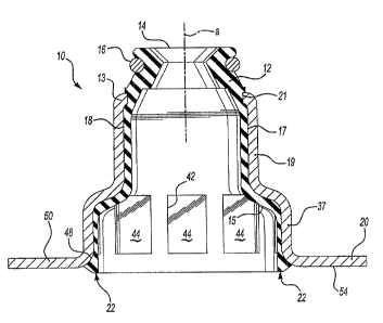
[0010] Figure 1 is a cross-sectional view of one embodiment of the valve stem
seal assembly of the present invention, revealing an elastomeric seal body and
metallic retainer to which the seal body is bonded in one preferred
embodiment.
[0011] Figure 2 is cross-sectional view of a second embodiment of a valve
stern
seal assembly, wherein the seal assembly is shown installed atop of a valve
guide
extending upwardly from a cylinder head deck, the seal assembly engaging a
valve
stem in accordance with contemplated usage of the present invention.
-3--
CA 02417619 2003-O1-29
DETAILED DESCRIPTION OF THE PREFERRED EMEODIMEN'TS
[0012) Referring initially to Figure 1, a valve stem seal assembly 10
incorporates
an elastomeric seal body 12 fixed to an end wall I3 of a cylindrical retainer
I9. The
seal body 12 is defined by a generally cylindrical structure having an axis a-
a, and
includes interior and exterior surfaces 15 and 17, respectively. The seal body
12 is
supported in the end wall 13 by means of an exterior groove 21 formed in the
exterior
surface 17 of the seal body, as revealed in Figure 1. The interior surface 15
of the seal
body 12 contains a circumferentially extending valve stem sealing lip I4
adapted to
engage a stem of a reciprocally movable valve stem assembly, a s will be
further
described. In the preferred form described herein, the seal body 12 also
incorporates a
valve guide sealing portion I8 adapted to engage a valve guide, as will also
be further
described.
[00I3] Referring now also to Figure 2, a second embodiment of the described
valve stem seal assembly 10 is shown installed over or atop a valve guide 30
in the
environment of an engine (not shown). As depicted, the seal assembly is
frictionally
secured to the annular valve guide 30, which in turn is press fit into, or
otherwise
frictionally secured within, an aperture 25 that extends through the
fragmentarily
shown cylinder head 24. It will be apparent that the valve stem assembly 10 is
actually installed over that portion of the valve guide that. protrudes above
the upper
deck 26 of the cylinder head 24. A valve stem 34 of a valve assembly 28 is
designed
to reciprocate within an aperture 31 that extends through the interior of the
valve
guide 30. It will be noted that in this embodiment the retainer I9' and its
endwall I3'
are formed differently than in the first described embodiment.
[0014] The operation of the valve stem seal assembly 10 and associated valve
assembly 28 may now be described as follows. During operation of an engine
(not
shown), the combustion process occurs in a rapid cyclic fashion. A valve 32
attached
to stem 34 is designed to open and close an intake (or exhaust) valve port 38
at a rate
of several times per second. A cam on a camshaft (neither shown) urges a cam
---q.-
CA 02417619 2003-O1-29
actuated end 36 of the valve stem 34 downwardly in a reciprocal cyclic manner
against the constant force of a valve return spring 40. In accordance with
Figure 2, it
will be appreciated that the return spring 40 bears against the upper surface
50 of a
bottom flange 20 of the retainer 19.
[0015] To the extent that the combustion process occurs within the cylinder
head
24, e.g. under the cylinder head deck 26, the valve 32 is positioned adjacent
the
combustion process.' Above the cylinder head deck 26 there exists an oily
environment, or one subj ect to "splash and spray oil" as described in the
art. As a
result, a valve stem seal assembly 10 is needed to assure that oil does not
migrate into
the area under the valve 32, i.e. the combustion chamber knot shown).
[0016] There are three migration paths along which oil may travel into the
combustion chamber. The first extends between the valve stem 34 and the
elastomeric sealing lip I4. As previously noted, the annular valve stem
sealing lip 14
is the primaxy gate for deterring oil travel along the first path. A garter
spring 16 is
disposed in an exterior groove of the seal body 12, circumferentially
tensioning the
sealing iip 14 against the stem 34 to compensate for wear of the lip over the
useful life
of the seal assembly.
[0417] The second migration path extends between the valve guide and the
interior surface 15 of the elastomeric seal body 12. h~ the: presently
described
embodiment, a portion of the interior surface 15 of the elastomeric seal body
comprises a valve guide sealing portion 18, that physically engages the guide
30 to
prevent oiI i~ow migration past the top surface 33 of the valve guide 30, and
down
along a path between the exterior surface 35 of the valve guide 30 and the
interior
surface 15 of the elastomeric seal 12.
[0018] The third migration path is by way of a gap 52, defined by the
interface of
the cylinder head deck 26 and the underside 54 of the bottom flange 20. The
gap 52
leads to the interface between the valve guide 30 and the aperture 25
extending
through the cylinder head 24. Thus the present invention contemplates that an
--5-
CA 02417619 2003-O1-29
elastomeric sealing media 22 is bonded at least to the interior annulus 48 of
the
bottom surface 54 of the flange 20 for preventing migration of oil along the
described
third migration path. In accordance with the described method of manufacturing
the
assembly 10, the bottom flange sealing media 22 will be contiguous with the
valve
guide-sealing portion 18, as well as the valve stem sealing lip 14.
[0019] The bottom flange sealing media 22 may be represented in several
distinct
embodiments. Although the embodiment described in Figures l and 2 displays
only
one configuration of the sealing media 22; i.e. attached to the inside annulus
area only
of the bottom flange 20, there are other possibilities, including the
application of a
solid layer of elastomeric material along the entire bottom surface of the
flange 20,
rather than only at the interior, or radially innermost, edge of the annular
bottom
flange 20. However, use of greater amounts of elastomeric material would be
excessive in a majority of applications.
[0020] Incidentally, the description of the seal body 12 has been simply an
elastomeric material. It will be appreciated by those skill in the art that
depending on
the internal pressures and oil migration flow patterns in a given engine, the
consistency of the elastomer can be modified with respect to its softness or
hardness
for achieving an optimal seal. In any event, it will be apparent to those
skilled in the
art that numerous other sealing media configurations may be viable or suitable
for the
desired purposes described.
[0021] Various methods can be employed for applying the elastomeric sealing
media 22 to the underside 54 of flange 2Q. For example, those skilled in the
art will
appreciate that the sealing media 22 can be screened printed or pad printed
onto an
underside or bottom 54 of the retainer flange 20.
[0022] Finally, it will be appreciated by those skilled in the art that a
bottom
interior portion 37 of the retainer 19 is spaced away from the exterior
surface 3S of
the valve guide 30. As such, there is little need for substantial application
of
elastomeric material within this region, to the extent that sealing of this
particular
-6-
CA 02417619 2003-O1-29
zone or region is not required. There is, therefore, provided an opportunity
to save
elastomeric material in the manufacture of the assembly 10.
[0023] One such method of saving elastomeric material provides that the
circumferential sealing media 22 is molded in-situ to the substrate material
of the
underside 54 of the bottom flange 20. This approach can be carried out by
physically
pouring molten elastomer into a mold provided in the interior portion of the
seal
assembly 10; i.e. within the retainer 19. In such a case, ribs 42 of elastomer
are
formed on the interior of the retainer (Figure l~ in areas where sprees and
internal
runners permit pressurized flow of elastomer to reach areas of the retainer 19
at the
bottom flange 20 in a manner adapted to apply the media 22 without wasting
elastomer: The various circumferentially spaced windows 44 of exposed metal
represent a savings of elastomer ilz areas where application of elastomeric
material is
not required. Thus, a cost savings is achieved by means of such a
manufacturing
procedure.
[0024] Although the described embodiments of this invention contemplate that
the retainer is formed of metal, other materials may be suitable depending
upon the
harshness of the particular environment. For example, some glass-filled nylons
or
other plastics may be suitable for some engine environments, wherein in such
cases
the retainer might suitably be fanned of plastic materials.
[0025] It is to be understood that the above description is intended to be
illustrative and not limiting. Many embodiments will be apparent to those of
skill in
the art upon reading the above descuiption. Therefore, the scope of the
invention
should be determined, not with reference to the above description, but instead
with
reference to the appended claims, along with the full scope of equivalents to
which
such claims are entitled.
-7-