Note: Descriptions are shown in the official language in which they were submitted.
CA 02424094 2003-03-31
WO 02/26579 PCT/USO1/30327
SELF-ADHESIVE CLOSURES
TECH1VICAL FIELD
This invention relates to self adhesive closures for packages.
BACKGROUND
In some instances, it is desirable to provide disposable articles with
reclosable
fasteners. For example, plastic bags for use in storing food (e.g., sandwich
bags and
similar bags of other sizes) are often provided with a reclosable closure
strip. Such
closure strips may be formed of a pressure sensitive adhesive, a "tongue and
groove" type
closure (e.g., "ZIP-LOC" closures), or a hook-and-loop fastener (e.g., a
"VELCRO"
fastener).
U.S. Patent No. 5,378,536 discloses a repositionable low tack or tack free
adhesive including a blend of an elastomeric block copolymer with a tackifying
material,
and mentions that one of the applications of such a material is in resealable
bags.
SUMMARY
The invention features self adhesive closures, and products including self
adhesive closures. Generally, the self adhesive closures include opposed
cooperating
fastener elements, each fastener element having a self adhesive surface. The
term "self
adhesive", as used herein, refers to a surface that exhibits adhesion to
itself (e.g., when
the surface is folded over on itself) and to surfaces having similar self
adhesive properties
(e.g., when the surface is pressed against a cooperating fastener element),
while
exhibiting relatively weaker adhesion to dissimilar surfaces and contaminants.
Preferred
self adhesive closures exhibit no significant adhesion to dissimilar surfaces
and
contaminants, and are thus substantially tack-free.
In one aspect, the invention features a package that includes a flexible bag
ZS defining an open end, and, positioned to seal the open end, a closure strip
including a
CA 02424094 2003-03-31
WO 02/26579 PCT/USO1/30327
self adhesive closure. The flexible bag is formed of a relatively non-self
adhesive
material.
In some preferred packages, the self adhesive closure includes a foam layer.
The
foam layer provides resiliency to enable the closure to seal around
contaminants, such as
particulate matter. Moreover, the foam allows for some lateral distortion of
the closure
without stressing the bond layer. When the closure is flexed, the foam layer
can undergo
shear distortion through its thickness (i.e., the inner and outer surfaces of
the foam layer
can be displaced laterally relative to one another) and thus reduce the shear
load applied
to the bond layer.
Some implementations of the invention include one or more of the following
features: The self adhesive closure includes a pair of opposed fastener
elements, each
fastener element having a self adhesive surface. Each fastener element
includes a layer
of flexible sheet-form material, a flexible foam layer bonded thereto, and a
self adhesive
layer covering at least a portion of an outer surface of the flexible foam
layer. The self
adhesive layer includes a thermoset elastomer. The foam is closed cell foam.
The self
adhesive closure is constructed to provide a watertight seal. The package
further includes
a second closure strip. The second closure strip includes a hook and loop
fastener, or,
alternatively, a non-reclosable shelf seal. The second closure strip is
positioned adjacent
the self adhesive closure, e.g., extending substantially parallel to the self
adhesive
closure. The package further includes a third closure strip. The self adhesive
closure is
positioned between the second and third closure strips. The flexible bag
includes a flap
constructed to fold over the open end. The closure strip is positioned to seal
the flap
against an outer surface of the bag. The edges of the flexible bag at the open
end lie in
the same plane.
In a further aspect, the invention features a closure strip including
cooperating
fastener elements of a self adhesive closure, each fastener element being
provided in the
form of an elongated strip, and including a self adhesive surface constructed
for
cooperative engagement with an opposed self adhesive surface of the other
fastener
element.
CA 02424094 2003-03-31
WO 02/26579 PCT/USO1/30327
Implementations of this aspect of the invention may include one or more of the
following features. Each fastener element includes a layer of flexible sheet-
form
material, a flexible foam layer bonded thereto, and a self adhesive layer
covering at least
a portion of an outer surface of the flexible foam layer. The self adhesive
layer includes
a thermoset elastomer. The foam is closed cell foam. The self adhesive closure
is
constructed to provide a watertight seal.
The invention also features methods of making bags including self adhesive
closures.
Some preferred self adhesive closures include a pair of opposed, cooperating
self
adhesive fastener elements, each fastener element including a laminate of a
flexible sheet
material, a flexible foam layer bonded to the flexible sheet material, and a
self adhesive
layer coated on an exposed surface of the flexible foam layer.
Note, however, that the flexible sheet material may be supplied as a portion
of bag
film or other flexible material to which the closure is applied in the
packaging
application, with the closure itself consisting essentially of a pair of foam
strips with self
adhesive layers which are applied to the bag film or other flexible packaging
material to
provide a releasable closure. Such closures are provided, in some instances,
with a heat-
sealable bonding layer on the sides of the foam strips opposite the self
adhesive layers,
for bonding the closure strips to the packaging material. Such closures can be
readily
p0 rolled and stored as continuous strip producis, to be cut to desired
lengths and bonded
during a bag-making operation, for example.
Suitable flexible sheet materials include flexible plastic films, e.g.,
polyethylene,
polypropylene, polyvinyl chloride, NYLON, and other flexible sheet materials
such as
fabrics, non-woven materials and papers. The flexible material should
generally have
?5 sufficient tear strength so that, when the flexible material is bonded to a
selected foam
layer, the fastener will resist tearing and permanent deformation during
normal use.
Suitable foams are those that have sufficient flexibility and strength to be
used in
a given application without tearing or interfering with proper operation of
the fastener.
Suitable foams will also provide the closure with resiliency, to allow the
closure strip to
CA 02424094 2003-03-31
WO 02/26579 PCT/USO1/30327
seal around contaminants and to allow lateral distortion of the closure strip
without
stressing of the bond. Preferably, the foam layer is formed of closed cell
foam to provide
a watertight seal. However, for applications in which ventilation is desired,
the foam
layer may be advantageously formed of an open cell foam. The thickness of the
foam
layer will depend upon the application in which the fastener is used. Thinner
foam layers
(e.g., with a thickness of 0.020 to 0.050 inch or 0.5 to 1.3 millimeters) are
more readily
run through conventional packaging equipment, and may be more suited for use
in
premade bags to facilitate dense stacking of the bags. Thicker foam layers
(e.g., with a
thickness of 0.050 to 0.125 inch or 1.3 to 3.2 millimeters) may be required
for
applications in which larger grains of particulate matter are to be contained,
or for
closures that are to be subjected to sharp distortions. Generally, it is
preferable that the
foam be at least 0.5 times as thick as the largest anticipated grain diameter,
preferably as
thick. Narrower foam strips (e.g., strips with a width of about 3116 to 3/8
inch or 5 to 10
millimeters) tend to be easier to open but are less able to seal about
particulate matter.
Wider foam strips (e.g., strips with a width of about 3/8 to 3/4 inch or 10 to
20
millimeters) can be harder to open but provide more compliance to seal about
grains.
Suitable foams include polypropylene, polyethylene and polyurethane, among
others.
The foam layer may be applied to the flexible sheet material in any desired
manner, e.g.,
by lamination, adhesion, or co-extrusion.
Z0 The self adhesive layer is formed of a material that provides a desired
degree of
self adhesion, combined with minimal adhesion to dissimilar surfaces and
contaminants.
Generally, the self adhesive layer is an elastomer that has been modified to
provide self
adhesive properties. Suitable self adhesive elastomers are described, e.g., in
U.S. Patents
Nos. 4,791,024, 4,956,228 and 4,985,299, the disclosures ofwhich are
incorporated
p5 herein by reference. For many bag closure applications, particularly those
configured
with interior anti-peel flaps, the optimum peel strength required of the
closure is very
low, such as about 0.2 to 0.4 pounds per lineal inch (0.35 to 0.7 Newtons per
lineal
centimeter), for easy opening. Such peel strength is provided, in some
embodiments, by
the engagement of the self adhesive layers, and in other embodiments by a
combination
CA 02424094 2003-03-31
WO 02/26579 PCT/USO1/30327
of the self adhesive engagement and the engagement of a primary, mechanical or
adhesive fastener. The thickness of the self adhesive layer will depend upon
the
properties required of the fastener, and the elastomer selected.
Preferably, the self adhesive elastomer is a thermoset material, particularly
for
applications which may be subjected to elevated temperatures during storage or
use, or
which require particularly good dimensional stability. For the self adhesive
material to
be suitable for repeated engagement cycles, the cohesive strength of the
material (as well
as the adhesion of the material to its carrier material, such as the foam
layer) must be less
than the force required to separate the two engaged layers of self adhesive
material.
Furthermore, for a "tack-free" characteristic as regards adhering to other
materials, the
self adhesive material should provide little to no adhesion (preferably, no
measurable
adhesion) to materials other than a contacting layer of similar material. As
discussed in
the reference patents incorporated above, a suitable adhesive material is an
elastomer
such as natural rubber dissolved in a solvent such as heptane (with a
proportion, for
example, of 15% natural rubber and 55% heptane). Another suitable adhesive is
a
mixture of elastomeric materials, such as natural rubber and butadiene-styrene
rubber.
For some applications in which the natural characteristics of a thermoset
material
are not required, a self adhering adhesive in the form of a thermoplastic
block copolymer,
such as that disclosed in U.S. Patent No. 5,378,536 (hereby incorporated
herein by
reference in its entirety), may be employed to advantage.
The self adhesive layer may be applied to the foam layer using any suitable
coating method, e.g., roll-coating or spraying.
The phrase "hook and loop fastener", as used herein, refers to reclosable
fasteners
that include a male fastener component having a plurality of male fastener
elements (e.g.,
hooks or mushrooms), and a female fastener component constructed for
cooperative
engagement with the male fastener component. This phrase also refers to
reclosable
"self engaging" touch fasteners having an array of male-type fastener elements
adapted
to engage a similar array of male-type fastener elements to form a releasable
closure.
CA 02424094 2003-03-31
WO 02/26579 PCT/USO1/30327
6
Advantageously, preferred closures of the invention are resealable,
repositionable,
relatively easy to open and close, provide a watertight seal when closed, and
are
relatively resistant to contamination, e.g., by dust or larger particulate
matter. A closure
strip including a self adhesive closure of the invention can advantageously be
used to seal
flexible, reclosable packages, such as plastic sandwich and storage bags.
Other features and advantages of the invention will be apparent from the
description and
drawings.
DESCRIPTION OF DRAWINGS
Figs. 1-7 are schematic perspective views of bags including self adhesive
closures.
Fig. 8 illustrates a second vertical form/fill bagging apparatus, configured
to
accommodate the closure strip of the invention.
Fig. 8A is an enlarged view of the means for joining the closure strip to the
bag
web in Fig. 8, with portions removed to show the configuration of the
insulator rail and
sealing jaws.
Fig. 9 is a cross-sectional view, taken along line 9-9 in Fig. 8.
Fig. 10 shows a first inverted horizontal form/fill packaging apparatus and
method, with the closure strip fed into the fin seal between the web flanges.
Fig. 10A is a cross-sectional view, taken along line l0A-l0A of Fig. 10.
Fig. 11 shows a second inverted horizontal form/fill packaging configuration,
with the closure strip wrapped about the web flanges.
Fig. 11A is a cross-sectional view, taken along line 11A-11A of Fig. 11.
Figs. 12A-12C illustrate three sample self adhesive closure constructions.
Fig. 13 shows an apparatus and method for forming bags to be filled from an
open
end opposite their closures.
Fig. 14 is a cross-sectional view, taken along line 14-14 in Fig. 13.
Fig. 15 is an enlarged view of area 15 in Fig. 13, showing the configuration
of the
closure as applied to the web.
CA 02424094 2003-03-31
WO 02/26579 PCT/USO1/30327
7
Fig. 16 shows another method for forming pouches, in which the closure strip
is
bonded to the edges of a sheet of bag film as the film is folded.
Fig. 17 illustrates making reclosable bags from two parallel plastic webs and
a
closure strip.
Fig. 17A shows a bag made by the process of Fig. 17.
DETAILED DESCRTPTION
Referring to Fig. 1, an envelope style package 10 is shown. Package 10
includes
a body 12 and a flap 14 that extends over upper edge 16 of body 12. Two
closures 18,
20, are provided to seal package 10. Each closure includes two opposed, strip-
form
fastener elements 18a, 18b and 20a, 20b. Closure 18 is a self adhesive,
reclosable
closure, while closure 20 is a non-reclosable, primary, shelf seal. Thus,
closure 20
provides supplemental sealing and tamper evidence of the package during
storage and
prior to use, and does not provide any closure function once opened. Closure
20 may be,
for example, a peel seal of an adhesive heat seal material containing
additives selected to
cause the peel seal to peel apart at a peel load lower than would be required
to fail the
underlying package film. Alternatively, closure 20 may be a permanent joint
between
opposing faces of packaging film 12, the package including a perforation 28 to
allow the
user to open the package without breaking the closure strip 20. Closure 18, on
the other
hand, is reclosable, meaning that it retains its engageable nature after
opening to provide
a reclosable seal. Closure 18 contains the self adhesive material featured in
the above
invention summary.
A face-to-face closing package 30 is shown in Fig. 2. Package 30 includes a
body 32 and, at its open end 34, edges 36a, 36b which generally lie in the
same plane.
Like package 10, package 30 includes a reclosable self adhesive closure 18 and
a shelf
seal closure 20. Package 30 also includes perforations 28a, 28b that are
constructed to
allow a user to easily tear off the shelf seal closure 20. (If desired, the
perforation may be
provided on one side only, as in a "pinch and pull" type package openable by
tearing
through a broad face of the package.)
CA 02424094 2003-03-31
WO 02/26579 PCT/USO1/30327
Figs. 3 and 3A show a roll top package 40 in its open and closed
configurations,
respectively. Roll top package 40 includes a reclosable self adhesive closure
18
including fastener elements 18a, 18b.
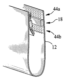
Figs. 4, 4A and 4B show various envelope-style packages that include both a
reclosable self adhesive closure 18 and a hook and loop closure 44. In the
embodiment
shown in Fig. 4, package 50 includes a reclosable self adhesive closure 18
interposed
between two associated hook and loop closures 44a, 44b. In the embodiment
shown in
Fig. 4A, a reclosable self adhesive closure 18 is positioned parallel to a
hook and loop
closure 44, with the hook and loop closure being positioned closer to the edge
46 of flap
14. In the embodiment shown in Fig. 4B, a reclosable self adhesive closure 18
is
positioned parallel to a hook and loop closure strip 44, with the
repositionable self
adhesive closure being positioned closer to the edge 46 of flap 14. In each of
the hybrid
configurations shown, the hook and loop closure provides mechanical strength
(i.e., peel
and shear strength) to the closure, while the self adhesive closure 18 gives
the hybrid
closure combination a desired degree of watertightness.
As shown in Figs. 5-7, either the self adhesive closure 18 (Fig. 5) or one of
the
sides of a combination closure (Figs. 6 and 7) may be constructed or attached
to the
packaging film 12 to form an interior "anti-peel" flap of the package, as is
described in
more detail in U. S. Patent No. 6,202,260, the entire contents of which are
hereby
incorporated by reference as if entirely set forth.
Figs. 8-16A illustrate examples of processes and equipment that are used to
apply
closure strips to flexible plastic sheet material to form reclosable bags.
Fig. 8 illustrates a vertical form and fill (VFF) machine configuration for
continuously securing the above-described closure strip to a flow of bag-
forming web
during the forming and filling of individual bags. The bag-forming web
consists of a thin
sheet of thermoplastic film 254 which is shaped into a tube by being fed over
a filling
tube 256, which has an upper funnel end 258 through which contents are
discharged to
fall into individual bags formed of the film. Film 254 is fed from a roll (not
shown) over
an attitude roller 260, and guided onto the fill tube by curved guide forms
262. In some
CA 02424094 2003-03-31
WO 02/26579 PCT/USO1/30327
cases, the film is advanced continuously and the transverse sealing jaws 264
(described
below) reciprocate vertically, traveling with the film during the
sealing/cutting process
(as indicated by arrows 265); in other cases the film is advanced
incrementally and the
transverse jaws remain within the same horizontal plane.
As film 254 is formed into a tube, its two longitudinal edges 268 form flanges
extending generally radially from the tube, between which a continuous length
of closure
strip 266 is fed in a folded condition, such that the edge regions of the web
film lie at
least partially against the outer sides of the closure strip in face-to-face
relation, but do
not overlap the folded edge of the closure strip. Guide rollers 270 above the
closure
0 sealing bars 272 maintain the adjacency of the sides of the closure strip
and the film
edges. Closure strip 266 is fed over a pair of counter-rotatable, parallel
rollers 273 to
separate the mated self adhesive strips without applying any shearing force,
and then
over a bisected insulating rail 274 extending longitudinally along the fill
tube from above
guide rollers 270 to below closure sealing bars 272. As shown in Figs. 8A and
9,
5 bisected insulating rail 274 consists of an outer rail 274a hanging from a
supporting rib
attaching rail 274a at its upper end to fill tube 256 just below rollers 273,
and an inner rail
274b extending radially from tube 256. These twin, parallel rail sections are
separated
along their length to form a space for accommodating the separated self
adhesive strips to
avoid crushing the foam layers of the strips as sealing bars 272 permanently
heat seal the
;0 closure strip to the edges of the bag film. The spacing of the rail
sections 274a, 274b also
helps to guide the closure strip through the sealing process. Outer rail 274a
also has a
notch extending along its distal end, for accommodating a middle grasp rib 132
of the
closure strip, if such is provided on the closure strip as discussed in U.S.
Patent No.
6,202,260, mentioned above. The primary purpose of insulating rail 274 is to
inhibit
,5 undesired welding of the inner sides of the closure strip together as the
edges of the bag
film are welded to the outer surfaces of the closure strip by closure sealing
bars 272, and
the primary purpose of the longitudinal space between rail sections 274a and
274b is to
avoid sliding contact against the self adhesive surfaces of the closure strip
during
processing. Other insulating rail constructions are also envisioned for
avoiding sliding
CA 02424094 2003-03-31
WO 02/26579 PCT/USO1/30327
contact of the self adhesive material, such as a twin, parallel endless belt
arrangement
(not shown) to form outer insulating rail sides that contact the self adhesive
surfaces of
the closure strip but move along with the closure through the sealing process.
Closure strip 266 may either be spooled from roll 276 over guide roll 278 in a
5 folded condition, as shown with its self adhesive strips 18a, 18b engaged,
and then pulled
over rollers 273 to peel apart the self adhesive strips, or the closure strip
may be spooled
flat and then folded onto the insulating rail, thereby avoiding having to
disengage the
self adhesive sections in the process.
Closure sealing jaws 272 each have a longitudinal groove adjacent the self
0 adhesive portions of closure strip 266, such that the heated sealing jaws
slidingly contact
the film edge regions only on either side of the self adhesive bands of the
closure strip,
sealing the film to the closure strip in two discrete bands. Sealing jaws 272
have
appropriate, embedded heating elements (not shown) to maintain their sealing
surfaces at
a predetermined, elevated temperature. To leave the inner edge of one side of
the closure
5 strip free from the film to form an anti-peel flap, the sealing jaw 272 on
that side of the
closure may be at least partially recessed, as shown, to avoid bonding the
inner edge of
that side of the closure strip to the bag film. To form an even wider anti-
peel flap, the
sealing jaw 272 on one side of the closure may be configured to contact the
bag film only
outboard of its self adhesive region.
0 Immediately below the lower edges of sealing jaws 272, insulating rail 274
terminates and the self adhesive bands of the closure strip are pressed
together between a
pair of rollers 280, just above the lower end of f 11 tube 256.
After a selected amount of contents have discharged through the lower end of
the
fill tube, transverse sealing jaws 264 come together about the bag film and
closure strip
and form two parallel, transverse seals 284, each of which will form the
sealed edge of a
bag. As jaws 264 travel with the advancing film, a cutting knife 282 within
the jaws
severs the film and closure strip between the transverse seals 284. When jaws
264 open
at the end of the sealing cycle, a fully formed, filled and severed bag 286 is
complete.
CA 02424094 2003-03-31
WO 02/26579 PCT/USO1/30327
11
Figs. 10 and 11 illustrate two examples of horizontal formlfill (HFF) machines
and processes featuring the above-described closure strips. Referring first to
Fig. 10, a
bag film 254 is continuously fed from roll 294 over attitude roller 296 and
into a forming
head 298 shaped to form the film into a rectangular tube 300. As with the VFF
method
described above, the edges of the film are brought together to form a
perpendicular fin
302 extending from one side of the tube. In this case, closure strip 100 is
fed from roll
304, folded to engage the hook and loop bands, passed about angled roller 306,
and fed
into the nip between heated fin seal rollers 308 between the edges of the bag
film.
Meanwhile individual products 310 to be packaged (e.g., trays of cookies) are
fed
through the forming head and into film tube 300 at a predetermined spacing and
rate
corresponding to the speed of the bag film.
As shown in Fig. 10A, the outer surfaces of folded closure strip 100 are
permanently welded to the extending film flanges forming the perpendicular fn
302 of
the film tube in the nip between fin seal rollers 308. No insulating rail is
needed between
the inner surfaces of the closure strip in this case because the outer
surfaces of rollers 308
are relieved in a region corresponding to the middle portion of self adhesive
closure 18 so
as to not apply excessive heat or pressure to the middle portion of the
closure, and the
edge regions of closure 18 are coated with a non-heat-sealable material 309 to
prevent
permanent sealing of closure 18. With proper adjustment of the temperature and
pressure
70 of rollers 308, which depends on the type of resin employed and the line
speed, among
other things, at most only a small amount of permanent bonding will occur
between the
engaged faces of closure 18. This small amount of bonding can advantageously
increase
the amount of peel force required to initially open the package, leaving a
sufficient
proportion of undamaged self adhesive surface to provide adequate engagement
upon
~5 reclosure.
The self adhesive strip construction 400 of Fig. 12A has a foam layer 402
applied
to a thermoplastic base 404 of the closure, a layer of self adhesive or
cohesive material
406 covering the upper surface of the foam layer, and two narrow strips of
high melt
temperature or heat barrier material 309 (e.g., MYLAR, NYLON or paper)
covering the
CA 02424094 2003-03-31
WO 02/26579 PCT/USO1/30327
12
longitudinal edge regions of the cohesive material to prevent permanent face
banding of
the closure if processed as shown in Fig. 10A. Fig. 12B shows a strip of
adhesive-coated
foam 408 applied to base 404 between two longitudinal ribs 410 disposed on
either side
of foam layer 402 to limit the facial compression of the foam layer during
processing or
during engagement in use. Both mating strips of a self adhesive closure can be
provided
with such ribs integrally molded with their bases 404, such that the ribs of
each strip
interfere with the ribs of the other strip as the two closure strips are
pressed together. Fig.
12C illustrates that foam layer 402 can be applied over ribs 410, such that
the ribs are
encased by the foam and limit compression of the edge regions of the foam
while
l0 allowing sufficient compression of the center region to accommodate
particulate
contamination.
Referring back to Fig. 10, diagonal offset folding rollers (not shown) fold
over the
fin seal, and a pair of offset rollers 312 carrying a heated seal bar and
cutting blade seal
the ends of the bags and sever the bags from each other.
L5 Fig. 11 shows a similar HFF process, in which the closure strip 100 is
folded over
on the outside of both the bag film flanges and a fin seal insulating rail 314
that extends
to just downstream of heated fin sealing rollers 308. Passed around angled
roller 306,
closure strip 100 is folded within a guide channel 316 such that the edges of
the closure
strip overlap the edges of the bag film, as shown in Fig. 11A. These
overlapped regions
>.0 are welded together on either side of insulating rail 314 by fin sealing
rollers 308a,
permanently bonding the closure strip to the bag film.
Other fin sealing arrangements will now also be apparent for attaching hybrid
or
combination closures, such as those featured in Figs. 4-4B, to bag film edges.
The hook
and loop closure portions of such closures can be arranged to be disposed
between the fin
sealing rollers, for example, with their self adhesive portions positioned
within the fin
seal and outboard of the fin sealing rollers as in Fig. I IA. Alternatively,
the self
adhesive portion may be positioned between the fin sealing rollers as in Fig.
10A., with a
hook and loop portion disposed outboard of the self adhesive portion.
CA 02424094 2003-03-31
WO 02/26579 PCT/USO1/30327
13
Fig. 13 shows another application of our closure strip in a bag-making
process.
Closure strip 318 contains a pull cord 320 (Fig. 1S) embedded along its
central rib 132.
The pull cord is configured to tear through the closure strip and bag film
longitudinally
between the self adhesive bands when pulled transverse to the closure strip,
and therefore
S must be of sufficient tensile strength to tear through the closure strip
resin without
breaking. Suitable pull cord materials include drawn nylons, such as fishing
Line, for
example. The pull cord is embedded within the resin of the center closure
strip rib by
being continuously fed into the rib-forming channel of the mold roll prior to
the
introduction of the rib-forming resin during molding of the closure strip
base.
Closure strip 318 is passed around a guide roller 324 to travel with bag film
2S4
onto a folding collar 326 where it is permanently bonded to the film under
heat and
pressure by a sealing shoe 328. As shown in Fig. 14, sealing shoe 328
slidingly engages
the closure strip along three bands, forming three continuous welds 330
between the
closure strip and bag film 254. Collar 326 supports the bag film against the
light pressure
1 S applied by the sealing shoe. The channels 332 and 334 in the sealing shoe
accommodate
a self adhesive band 18a and center rib of the closure strip, respectively,
and maintain the
transverse location of the closure strip during bonding. The exposed outer
edge of the
closure strip is not welded to the bag film in this instance, to provide an
internal anti-peel
flap in the finished bag, as shown in Fig. 1S. Other bonding configurations
are employed
?0 for various applications.
Once welded together, bag film 2S4 and closure strip 318 are folded along
their
longitudinal centerline and passed between two drive rollers 336 that press
the cohesive
bands of the closure strip together and ensure an appropriate crease along the
spine of the
closure strip. The folding of the bag film and closure strip is effected by
collar 326 and a
?S creasing idler 338 that runs along the center of the closure strip and
defines a rim groove
340 for receiving the center rib 132 of the closure strip during folding.
The folded bag film next passes between a pair of reciprocating
sealing/cutting
jaws 342 which close against the outer surfaces of the bag film to seal the
two sides of the
folded bag film and the folded closure strip together to form a series of
individual
CA 02424094 2003-03-31
WO 02/26579 PCT/USO1/30327
14
pouches, each pouch sealed on three sides and having a single open end 344 for
subsequent filling. Jaws 342 may be configured to also sever the pouches from
each
other during sealing, or to leave the pouches connected in the form of a
string of pouches
that is readily pulled through an adjacent filling/closing station (not
shown).
In the bag-forming method shown in Fig. 16, closure strip 318, already folded
in
half, is fed across an angled roller 356 and between the longitudinal edges
358 ofbag
film 254 as the film is folded within collar 326. A pair of grooved and heated
sealing
rollers 360 continuously seals the edge regions of the bag film to the
overlapping closure
strip. No insulating rail is necessary as the self adhesive bands of the
closure strip are
configured as shown in Fig. 12A and the rollers are contoured so as to not
bear upon the
center region of the foam layers. After passing through edge sealing jaws 342,
the folded
edge 362 of the bag film is trimmed away along line 364, leaving the ends of
the pouches
opposite the closure strip open for receiving materials to be packaged. The
series of
pouches may then be spooled into a roll for sale or later filling.
I S Fig. 17 shows a method of making bags from two separate sheets of bag film
and
the above-described bag closure strip. Upper and lower plastic films 368 and
370,
respectively, are unspooled continuously, with either a pre-folded closure
strip, or pre-
engaged self adhesive strips 372, fed between them as shown. The closure
strips are each
permanently welded to respective inner sides of the plastic films between two
rotary
?0 sealing rolls 376 (only the upper roll is shown). The parallel films and
closure strips are
then welded together at spaced intervals by transverse heated sealing jaws
378, forming
side seals between adjacent bags which are then filled from their open ends
(not shown)
and closed by upper and lower sets of sealing jaws 380. This process is also
useful, for
instance, for,forming a series of pre-made bags to be rolled or stacked for
later filling.
?5 The bag 382 formed by this process has four side seals 384, as shown in
Fig. 17A,
along with closure 372. The side seal 384 adjacent and parallel to closure 372
is ripped
off to open the bag and expose the closure. In another embodiment (got shown)
the side
seal 384 adjacent and parallel to closure 372 is omitted, along with the upper
set of
sealing jaws 380 in Fig. 17, and a folded closure strip is inserted in place
of separate
CA 02424094 2003-03-31
WO 02/26579 PCT/USO1/30327
strips 372, with the fold of the closure strip pointing outward toward the
adjacent side of
the continuous films.
Other embodiments are within the scope of the invention and the following
claims.