Language selection

Search

Patent 2424109 Summary

Third-party information liability

Some of the information on this Web page has been provided by external sources. The Government of Canada is not responsible for the accuracy, reliability or currency of the information supplied by external sources. Users wishing to rely upon this information should consult directly with the source of the information. Content provided by external sources is not subject to official languages, privacy and accessibility requirements.

Claims and Abstract availability

Any discrepancies in the text and image of the Claims and Abstract are due to differing posting times. Text of the Claims and Abstract are posted:

  • At the time the application is open to public inspection;
  • At the time of issue of the patent (grant).
(12) Patent: (11) CA 2424109
(54) English Title: DEVICE FOR SUPPLYING AN ELECTRO-PEN WITH ELECTRICAL ENERGY
(54) French Title: DISPOSITIF D'ALIMENTATION EN ENERGIE ELECTRIQUE D'UN STYLO ELECTRIQUE
Status: Deemed expired
Bibliographic Data
(51) International Patent Classification (IPC):
  • A61B 18/14 (2006.01)
  • A61N 1/18 (2006.01)
(72) Inventors :
  • METZGER, ROGER (Switzerland)
(73) Owners :
  • SYNTHES USA, LLC (United States of America)
(71) Applicants :
  • SYNTHES (U.S.A.) (United States of America)
(74) Agent: OSLER, HOSKIN & HARCOURT LLP
(74) Associate agent:
(45) Issued: 2011-03-29
(86) PCT Filing Date: 2000-10-04
(87) Open to Public Inspection: 2002-11-04
Examination requested: 2005-09-12
Availability of licence: N/A
(25) Language of filing: English

Patent Cooperation Treaty (PCT): Yes
(86) PCT Filing Number: PCT/CH2000/000541
(87) International Publication Number: WO2002/028301
(85) National Entry: 2003-03-31

(30) Application Priority Data: None

Abstracts

English Abstract


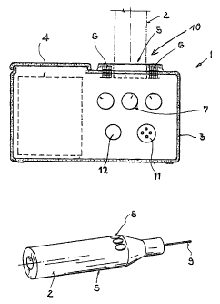
The invention relates to a device for supplying electrical energy to an
electro-pen (2) with an electric drive unit for driving a tool. The device
comprises a console with an energy supply unit (1) which supplies the electric
drive unit of the electro pen (2) with electrical energy. Said console with
the energy supply unit (1) is equipped with an accumulator (4). The electrical
energy supply from the console with the energy supply unit (1) to the electro-
pen (2) takes place either via a sterilisable cable or inductively without an
electrical connection. The console with the energy supply unit (1) is
configured in such a way that it can be steam-sterilised. The device is mobile
since it is not physically connected to a mains supply or a console. Sterility
is also guaranteed.


French Abstract

L'invention concerne un dispositif servant à alimenter en énergie électrique un stylo électrique (2) doté d'une unité d'entraînement électrique pour l'entraînement d'un outil. Ce dispositif comprend une console équipée d'une unité d'alimentation en énergie (1), qui alimente en énergie électrique l'unité d'entraînement électrique du stylo électrique (2). Cette console avec unité d'alimentation en énergie (1) comprend un accumulateur (4). L'alimentation d'énergie électrique de la console avec unité d'alimentation en énergie (1) au stylo électrique (2) s'effectue soit par un câble stérilisé soit par induction sans connexion électrique. Cette console avec unité d'alimentation en énergie (1) est conçue de manière à pouvoir être stérilisée à la vapeur. Ledit dispositif est mobile du fait qu'il n'est pas relié spatialement à une connexion réseau ou à une console. La stérilisation est en outre garantie.

Claims

Note: Claims are shown in the official language in which they were submitted.


The embodiments of the present invention for which an exclusive property or
privilege is
claimed are defined as follows:


1. Device for supplying electrical energy to an electropen (2) with an
electrical drive
unit for driving a tool where the device includes a console with energy supply
unit (1) which
supplies the electrical drive unit of the electropen (2) with electrical
energy, characterized by
the fact that

A) the console with energy supply unit (1) is equipped with an accumulator
(4),

B) the supply of electrical energy from the console with energy supply unit
(1) to the
electropen (2) takes place either via a cable which can be sterilized or
inductively without
electrical connection, and

C) the console with energy supply unit (1) is configured to be liquid-tight.

2. Device according to claim 1, characterized by the fact that at least one of
its electrical
and electronic components are configured to be liquid-tight.

3. Device according to claim 1 or 2, characterized by the fact that the
console with
energy supply unit (1) is configured to be independent of a mains and thus
mobile.

4. Device according to any one of claims 1 to 4, characterized by the fact
that the
console with energy supply unit (1) has a connection (11) to a mains for
charging the
accumulator (4).

5. Device according to any one of claims 1 to 4, characterized by the fact
that the
console with energy supply unit (1) has an electrical cable connection (12)
for connection to
the electropen (2) by means of a cable which can be sterilized.

6. Device according to any one of claims 1 to 5, characterized by the fact
that the
console with energy supply unit (1) has a receiving holder (10) at which the
electropen (2)
can be received for charging and where the inductive or electrical coupling
between the
console with energy supply unit (1) and electropen (2) can be produced.

7. Device according to any one of claims 1 to 6, characterized by the fact
that either a
sterilizable accumulator or non-sterilizable accumulator can be introduced
sterilely into the
console with energy supply unit (1) with the aid of a sterile covering.


6

8. Device according to any one of claims 1 to 7, characterized by the fact
that a
switched-mode power supply is used to charge the accumulator (4).

9. Electropen (2) for use with a device according to any one of claims 1 to 8,

characterized by the fact that, in the electropen (2), an electrical energy
storage device,
preferably a capacitor or an accumulator, is installed which can be charged
through an
electrical or inductive coupling with a corresponding device on the console
with energy
supply unit (1) of the device via its accumulator (4).

10. Device according to any one of claims 1 to 8 with an electropen (2)
according to
claim 9, characterized by the fact that for electrical coupling one or more
transformers (6)
with at least two contacts are provided in the console with energy supply unit
(1) of the
device and in the electropen (2).

Description

Note: Descriptions are shown in the official language in which they were submitted.


CA 02424109 2010-06-17

1 -
Device for Supplying an Electro-Pen with Electrical Energy

The invention relates to a device according to the preamble of claim I as well
as an electropen for use with such a device
according to the preamble of claim 9.

Such devices of the generic type find application especially in medicine, in
particular in surgery. Electropens are even used, for
example, in operations in the visual and hand area.

Electropens according to the state of the art consist of a drive unit in the
form of a pen, i.e., in the form of a pen holder, an
electric cable, and a console which converts the mains voltage into a low
voltage suitable for the drive unit.

From DE-OS 197 13 224 A 1 an electromagnetic pen is known for the treatment of
humans and animals. It serves, with the aid of
magnetic fields of low intensity, to introduce drugs through the skin of
humans and animals without perforating the skin. This
electropen is operated with two microbatteries connected in tandem.

These electropens known according to the aforementioned state of the art have
the disadvantage that the console with energy
supply unit cannot be sterilized due to its construction. Furthermore, the
console as a rule is plugged into a socket outlet and is
thus immobile.

The objective of the present invention is to provide a device for supplying an
electropen with electrical energy, said device being
mobile and not physically connected to a mains supply or to a console,
wherewith sterility is guaranteed.

According to the invention this objective is realized by the characterizing
clause of claim 1.


CA 02424109 2003-03-31

2
The device according to the invention has the advantage that the cable to the
mains is omitted and thus mobility is ensured.
Through the omission of a battery in the electropen, the latter is
significantly lighter and thus easier to handle. At the same time
any connection of the electropen to the unsterile area is avoided. A further
advantage lies in the fact that all the functions of the
device can be operated directly by the operator.

In one variant, the electropen used together with the device has, in addition,
the advantage that the supply cable is omitted and no
large and heavy accumulator has to be integrated into the electropen itself.

Additional advantageous developments of the invention follow from the
subordinate claims.

The console with energy supply unit is expediently configured to be liquid-
tight in order to ensure that it can be sterilized and is
resistant to hot steam. Steam sterilizability occurs at a temperature of 143
C, a relative humidity of 100%, and a pressure of 3
bar.

An embodiment example of the invention is represented in the single figure.

The single figure shows the device according to the invention with console and
energy supply unit as well as an electropen.

The console with energy supply unit is denoted in the single figure by the
reference number 1. From this, the electropen 2 is
supplied with electrical energy either directly via a cable or indirectly via
a charging device and small energy storage device. The
electropen 2 is equipped with an electrical drive unit 5 for driving a tool.
As a rule the electrical drive unit 5 is an electric motor,
although other drive units are also conceivable which are moved through
translation instead of through rotation.

The console and energy supply unit I can be sterilized according to the
invention. For this purpose the console and energy supply
unit I is enclosed in a liguid-tight housing 3. Since the console and


= CA 02424109 2003-03-31

3
energy supply unit I can be sterilized, they can be operated directly by the
surgeon, unlike a traditional console and energy
supply unit 1.

The console and energy supply unit I is independent of the mains and thus
mobile and equipped for this purpose with the
accumulator 4 as energy source.

In an embodiment variant, a small, rapidly chargeable electrical energy source
(for example, a capacitor) is housed in the
electropen 2 which can be charged via the accumulator 4 through an electrical
or inductive coupling with a corresponding device
on the console with energy supply unit 1. This has the advantage that a large
and heavy accumulator does not have to be used in
the electropen 2. For charging, either electrical contacts or a transformer 6
with at least one coil is used in the console and energy
supply unit 1 and in the electropen 2.

The console has a receiving holder 10 at which the electropen can be received
for charging.

Since the console with energy supply unit I is independent of the mains, due
to the accumulator 4 and the construction-related
omission of electrical cable feeds from the mains to the console with energy
supply unit 1, the entire system is no longer bound to
one workplace and is thus mobile and can be moved from one place to another
during an operation.

The reference number 7 denotes operating elements of the console with energy
supply unit 1 and the reference number 8 denotes
the operating elements of the electropen 2.

The console with energy supply unit I can however also have a cable connection
12 for operating the electropen 2 (via a cable
which can be sterilized), as represented in the single figure.


CA 02424109 2003-03-31

4
Finally, the console with energy supply unit I is also still provided with a
connection 11 to the mains for charging the
accumulator 4.

Representative Drawing
A single figure which represents the drawing illustrating the invention.
Administrative Status

For a clearer understanding of the status of the application/patent presented on this page, the site Disclaimer , as well as the definitions for Patent , Administrative Status , Maintenance Fee  and Payment History  should be consulted.

Administrative Status

Title Date
Forecasted Issue Date 2011-03-29
(86) PCT Filing Date 2000-10-04
(87) PCT Publication Date 2002-11-04
(85) National Entry 2003-03-31
Examination Requested 2005-09-12
(45) Issued 2011-03-29
Deemed Expired 2015-10-05

Abandonment History

There is no abandonment history.

Payment History

Fee Type Anniversary Year Due Date Amount Paid Paid Date
Application Fee $300.00 2003-03-31
Maintenance Fee - Application - New Act 2 2002-10-04 $100.00 2003-03-31
Registration of a document - section 124 $100.00 2003-07-04
Maintenance Fee - Application - New Act 3 2003-10-06 $100.00 2003-10-03
Maintenance Fee - Application - New Act 4 2004-10-04 $100.00 2004-10-04
Request for Examination $800.00 2005-09-12
Maintenance Fee - Application - New Act 5 2005-10-04 $200.00 2005-09-23
Maintenance Fee - Application - New Act 6 2006-10-04 $200.00 2006-10-03
Maintenance Fee - Application - New Act 7 2007-10-04 $200.00 2007-09-18
Maintenance Fee - Application - New Act 8 2008-10-06 $200.00 2008-10-01
Registration of a document - section 124 $100.00 2009-03-13
Maintenance Fee - Application - New Act 9 2009-10-05 $200.00 2009-10-02
Maintenance Fee - Application - New Act 10 2010-10-04 $250.00 2010-09-21
Final Fee $300.00 2011-01-05
Maintenance Fee - Patent - New Act 11 2011-10-04 $250.00 2011-09-27
Maintenance Fee - Patent - New Act 12 2012-10-04 $250.00 2012-09-12
Maintenance Fee - Patent - New Act 13 2013-10-04 $250.00 2013-09-13
Owners on Record

Note: Records showing the ownership history in alphabetical order.

Current Owners on Record
SYNTHES USA, LLC
Past Owners on Record
METZGER, ROGER
SYNTHES (U.S.A.)
Past Owners that do not appear in the "Owners on Record" listing will appear in other documentation within the application.
Documents

To view selected files, please enter reCAPTCHA code :


To view images, click a link in the Document Description column. To download the documents, select one or more checkboxes in the first column and then click the "Download Selected in PDF format (Zip Archive)" or the "Download Selected as Single PDF" button.

List of published and non-published patent-specific documents on the CPD .

If you have any difficulty accessing content, you can call the Client Service Centre at 1-866-997-1936 or send them an e-mail at CIPO Client Service Centre.


Document
Description 
Date
(yyyy-mm-dd) 
Number of pages   Size of Image (KB) 
Representative Drawing 2011-02-25 1 8
Cover Page 2011-02-25 2 44
Abstract 2003-03-31 2 85
Claims 2003-03-31 2 61
Drawings 2003-03-31 1 15
Description 2003-03-31 4 94
Representative Drawing 2003-03-31 1 13
Cover Page 2003-06-05 1 39
Claims 2009-12-31 2 65
Drawings 2009-12-31 1 14
Description 2010-06-17 4 93
PCT 2003-03-31 3 111
Assignment 2003-03-31 2 82
Correspondence 2003-06-02 1 24
Assignment 2003-07-04 2 62
Correspondence 2003-07-04 1 39
PCT 2003-04-01 2 62
Prosecution-Amendment 2005-09-12 1 30
Assignment 2009-03-13 11 620
Prosecution-Amendment 2009-07-03 2 48
Prosecution-Amendment 2009-12-31 7 208
Correspondence 2010-06-17 3 66
Correspondence 2011-01-05 1 43