Note: Descriptions are shown in the official language in which they were submitted.
CA 02425999 2003-04-15
WO 02/36240 PCT/CA01/01479
IMPROVED AIR/OIL SEPARATOR
FIELD OF THE INVENTION
The present invention relates to an apparatus for separating a liquid in
suspension, and more particularly to an apparatus for air/oil separation espe
cially but not exclusively for use in gas turbine engine oil systems.
BACKGROUND OF THE INVENTION
Oil systems, particularly gas turbine engine oil systems require sepa-
rators for separating air and oil from the mixture produced during operation.
These mixtures vary from oil emulsified with air to air contaminated by
droplets
of oil. For example, the compressed air streams used in gas turbine engines to
pressure labyrinth seals for the engine main bearings in order to avoid exces-
sive loss of a lubricating oil, almost invariably become contaminated with oil
in
the form of droplets suspended in the air. Contamination of the compressed air
with oil mist is particularly disadvantageous because, loss of contaminated
air
from the labyrinth seals in the compressor causes fouling of the engine parts
and produces noxious and unpleasant products in air drawn from the compres-
sor for cabin pressurization. A further disadvantage is, of course, the
increased
loss of the lubricating oil from the engine oil reservoir, necessitating
larger
capacity reservoirs and adding to the weight of the engine. It has been a
particular problem that even relatively small inefficiencies in such
separators
lead to the loss of a significant quantity of lubricating oil during each hour
of
operation of the engine.
Centrifugal separators have been extensively used in the aircraft industry
in attempts to remove the majority of oil mist from compressed air streams. An
example is described in United States patent 4,714,139 issued to Lorenze et
al.
on December 22, 1987 in which an air/oil separator is used in a gas turbine
power plant especially for an aircraft that includes a pump used for the
separation of the air and the oil, out of the air/oil mixture. The pump is so
constructed that centripetal and centrifugal forces are employed for the
air/oil
separation. The air passes by centripetal force through a sponge type filter
CA 02425999 2003-04-15
WO 02/36240 PCT/CA01/01479
2
structure and out through a hollow central shaft mounting the pump wheel or
forming an integral one-piece component with the pump wheel. The oil does not
travel through the filter but is reversed in its travel direction by
centrifugal force
for return into the lubricant circulating system.
Another example is United States patent 4,755,103 which issued to
Streifinger on July 5, 1988. Streifinger describes means for separating an
air/oil
mixture and for returning oil droplets to a circulation having oil consuming
devices, which includes a porous air-permeable element built into the hollow
main shaft between two oil impermeable walls whereby outer feed openings for
the air/oil mixture are arranged in the upstream wall which correspond to open-
ings in the main shaft while an air discharge opening is arranged through the
downstream wall in its center which is in communication with the vent line.
The
oil is prevented from flowing out of the air discharge opening by centrifugal
force
and it is thrown back into the bearing chamber and is fed back to the tank by
way of the suction line.
The disadvantage of the above prior art lies in that the oil separated from
the air/oil mixture travels in a reverse direction relative to the air/oil
mixture flow
in the sponge type filter or the porous air-permeable element, and exits from
the
inlet for admitting the air/oil mixture, thereby creating a blockage and
increasing
the delta pressure across the air/oil separator, resulting in loss of
efficiency.
Smith describes, in United States patent 4,049,401 issued on
September 20, 1977, a centrifugal separator for separating suspensions of oil
mist in air and especially intended for use with aircraft engines. The
separator
comprises a rotatable chamber filled with a relatively rigid porous material
and
driven by a hollow shaft. An inlet for the suspension is provided in one end
wall
of the chamber and separate outlets for oil and air in the form of an
apertured
chamber outer wall and apertures in the shaft respectively. A buffer is
positioned within the chamber between two different grades of porous material
to facilitate radial movement of the oil droplets in the porous material. The
oil
droplets are directed away from the air/oil mixture flow path, thereby
reducing
the blockage and therefore the delta pressure across the air/oil separator.
CA 02425999 2003-04-15
WO 02/36240 PCT/CA01/01479
3
However, as pointed out by Smith, it has proven possible to dispense with the
buffer and the differing grades of porous material without any significant
loss of
efficiency. In other words, the buffer and differing grades of porous material
have not improved the efficiency of the separator.
Therefore, there is a need for an improved air/oil separator for more
efficient separation of the air/oil mixture.
SUMMARY OF THE INVENTION
It is one object of the present invention to provide an air/oil separator with
a relatively higher efficiency of separation.
It is another object of the present invention to provide an improved form
of separator suitable for use in aircraft and lending itself to the
construction of a
modular and interchangeable separator that is simply constructed and
relatively
economical to manufacture.
In accordance with the present invention there is provided an apparatus
adapted for separating a liquid suspended in a gas, comprising a rotatable
vessel defining a chamber and a packing within the chamber adapted to rotate
with the vessel. The rotatable vessel has an inlet at a first end of the
chamber
for admitting the gas having the liquid suspended into the chamber, an outlet
for
the liquid in the vessel in a radially outer part of the chamber and an outlet
for
the gas in the vessel, in a radially inner part of the chamber at a second end
thereof. The packing includes a substantially rigid matrix adapted to inhibit
collapse under centrifugal forces during rotation of the vessel, the matrix
including interstices defining a plurality of flow passages permeable to the
liquid
and gas for both axial and radial movement of the liquid and gas therethrough.
A cut-away area is formed in the packing to facilitate ejection from the
packing
of liquid droplets formed in the passages of the packing, whereby the passages
are relatively cleared to facilitate a continuous movement of a succeeding
portion of the mixture of the liquid and gas therethrough..The cut-away area
preferably extends inwardly and radially from an outer periphery of the
packing.
CA 02425999 2003-04-15
WO 02/36240 PCT/CA01/01479
4
It is also preferable that the cut-away area is axially located close to the
first end
of the chamber, and axially aligns with the liquid outlet of the chamber.
In one embodiment of the present invention the cut-away area comprises
a plurality of bores circumferentially spaced apart from one another,
extending
radially from the outer periphery of the packing.
In another embodiment of the present invention the cut-away area
comprises an annular groove extending radially from the outer periphery of the
packing.
In accordance with another aspect of the present invention, an air/oil
separating arrangement is provided for a machine having a rotatable hollow
shaft. In the arrangement a vessel defining a separating chamber is mounted to
the hollow shaft and adapted to rotate together with the hollow shaft. The
vessel
has an inlet at a first end of the separating chamber for admitting a mixture
of
air and oil mist under a pressure differential between outside of the chamber
and inside of the hollow shaft, an outlet in a radial inner part of the
chamber in
communication with the inside of the hollow shaft for exhausting the air into
the
hollow shaft under the pressure differential, and an outlet in the vessel in a
radial outer part of the chamber for expelling oil droplets out of the chamber
under centrifugal forces during rotation of the chamber. A packing is filled
within
the chamber adapted for rotation with the chamber. The packing has a substan-
tially rigid matrix adapted to inhibit collapse under the centrifugal forces.
The
matrix includes interstices defining a plurality of flow passages permeable to
the
air and oil mist for both axial and radial movement of the air and oil there-
through. A cut-away area formed in the packing radially extending from an
outer
periphery of the packing to facilitate ejection from the packing of the oil
droplets
formed in the passages of the packing, whereby the passages are cleared to
facilitate a continuous movement of a following portion of the mixture of the
air
and oil mist.
The cut-away area is preferably located axially close to but spaced apart
from an end of the packing adjacent to the inlet. It is also preferable that
the oil
outlet is axially located close to the first end of the chamber and axially
aligns
CA 02425999 2003-04-15
WO 02/36240 PCT/CA01/01479
with the cut-away area of the packing while the air outlet is axially located
close
to a second end of the chamber.
Preferably, the vessel defining the separating chamber is sealingly
mounted to the hollow shaft, and an annular space formed between the radially
5 inner part of the chamber and the hollow shaft communicates with the inside
of
the hollow shaft through at least one aperture through a wall of the hollow
shaft
so that a pressure at the air outlet of the chamber is maintained lower than
the
pressure at the inlet and the oil outlet of the chamber.
The air/oil separator according to the present invention advantageously
provides an efficient solution with a relatively simple structure for
separating oil
suspended in air. A major proportion of the oil suspended in the air forms oil
droplets in the passages of the packing at a first stage after entering the
packing. The major proportion of oil droplets formed in the passages at the
first
stage will partially block the passages and slow down the continuous movement
of a following portion of the mixture in the passages although the oil
droplets are
eventually ejected away radially by centrifugal forces. The cut-away area
formed close to the inlet is used as an early exit from the passages in the
packing and a temporary reservoir for the major proportion of the oil droplets
so
that the oil droplets formed in the passages at the first stage are collected
in the
cut-away area and quickly ejected from the packing to clear the passages and
facilitate a continuous movement of a following. portion of the mixture of air
and
oil.
Other advantages and features of the invention will be better understood
with reference to the preferred embodiments described below.
BRIEF DESCRIPTION OF THE DRAWINGS
Having thus generally. described the nature of the invention, reference
will now be made to the accompanying drawings, showing by v~iay of
illustration
the preferred embodiments thereof in which:
CA 02425999 2003-04-15
WO 02/36240 PCT/CA01/01479
6
Fig. 1 is a longitudinally cross-sectional view of an air/oil separator
mounted on a hollow shaft according to one preferred embodiment of the
invei-ition;
Fig. 2 is,a cross-sectional view of the air/oil separator taken along line 2-
2 in Fig. 1 and rotated 90° counterclockwise;
Fig. 3 is a longitudinally cross=sectional view of the air/oil separator
taken along line 3-3 and detached from the hollow shaft; and
Fig. 4 is a longitudinally cross-sectional view of a air/oil separator
according to another preferred embodiment of the invention.
DETAILED DESCRIPTION OF THE PREFERRED EMBODIMENTS
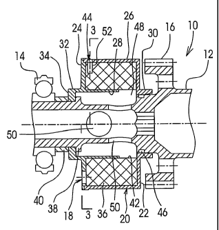
Referring to the drawings, particularly to Figs. 1 through 3, a rotatable
centrifugal separator 10 is mounted on a hollow shaft 12 of a gear box for a
jet
engine. The hollow shaft 12 is rotatably supported in bearings, only one of
which is shown and indicated at numeral 14, and is driven from a main shaft of
the engine (not shown) by way of gear 16. A mixture including oil mist
suspended in air is passed via the gear box casing (not shown) to the inlet 18
for the separator 10.
The separator 10 includes a rotatable chamber 20 forrr~ed by a rear
wall 22, a front walls 24, outer cylindrical wall 26 and inner cylindrical 28.
The
rear wall 22 and the outer cylindrical wall 26 are made as an integral piece
while
the front wall 24 and the inner cylindrical wall 28 are made as another
integral
piece. The rear wall 22 includes an annular and axial flange 30, and the front
wall 24 includes an annular flange 32 having a. radial section 34 so that the
assembly of chamber 20 is radially supported on the hollow shaft 12 through
the
flanges 30 and 32.
Inside the chamber 20 there is provided a packing 36 snugly fit between
and frictionally engaging the outer and inner cylindrical walls 26 and 28 so
that
the assembly of the chamber 20 is secured together. The assembly of
chamber 20 is axially restrained on the hollow shaft 12 through the radial
section 34 of the flange 32 which is forced to abut an annular shoulder 38 of
the
CA 02425999 2003-04-15
WO 02/36240 PCT/CA01/01479
7
hollow shaft 12 by, for example, a nut (not shown) via the bearing 14 and an
annular spacer 40. The assembly of chamber 20 is rotatable together with the
hollow shaft 12, connected to the hollow shaft 12 by any well known means,
such as a key and a notch, not shown.
An annular air outlet 42 is formed between the rear wall 22 and the end
of the inner cylindrical wall 28 because the inner cylindrical wall 28 is
shorter
than the outer cylindrical wall 26. An oil outlet 44 is provided in the outer
cylindrical wall 26. Seals are provided between the chamber 20 and the hollow
shaft 12 one of which, as an example, is shown and indicated at numeral 46,
whereby a pressure difference is maintained between the outside of the
chamber 20 and the inside of the hollow shaft 12. An annular space 48 is
formed between the inner cylindrical wall 28 of the chamber 20 and the hollow
shaft 12 to communicate with the inside of the chamber 20 through the outlet
42
and the inside of the hollow shaft 12 through the apertures 50 in the wall of
the
hollow shaft 12 to maintain the pressure at the outlet 42 lower than the
pressure
at the inlet 18, thereby causing a flow of the mixture of air and oil mist
entering
the inlet 18, and a flow of air exiting from the outlet 42 to enter the inside
of the
hollow shaft 12. The air generally will not escape from the outlet 44 when
passing through the packing 36 because the air flows towards the outlet 42
under the pressure difference between the inlet 18 and the outlet 42 while
there
is no pressure difference between the inlet 18 and the outlet 44. On the other
hand, the mixture of the air and oil may enter the outlet 44 because of the
pressure difference between the outlet 44 and the outlet 42. Nevertheless, a
majority of the mixture of air and oil mist will be admitted to the chamber 20
through the inlet 18 but not the outlet 44 because the oil droplets formed in
the
passages of the packing 36 radially move toward the outlet 44 under
centrifugal
forces resulting in a blockage to the mixture of air and oil mist entering
outlet 44.
A most satisfactorily permeable and substantially rigid matrix material to
form the packing 36, is the product RetimetTM made by the Dunlop Company
Ltd. RetimetTM includes a mesh of metal formed by plating a metal onto a
synthetic open-celled formed structure and subsequently leaching out and/or
CA 02425999 2003-04-15
WO 02/36240 PCT/CA01/01479
otherwise removing the synthetic material. By substantially rigid it is meant
that
the matrix is capable of withstanding the centrifugal and other loads imposed
on
it during operation of the separator without suffering a significant amount of
deformation which would tend to close the mesh and,unduly restrict the flow of
the mixture of air and oil therethrough. One particular advantage that stems
from the use of RetimetTM is that it can be radially machined approximately to
size and is sufficiently deformable to allow it to be sized by compressing
prior to
its insertion into the chamber 20.
The matrix material, nevertheless, could be formed of any suitable mesh
material, for example, wire gauze or expanded mesh, a plurality of pierced
plates, or alternatively a bristle structure. The essential feature of the
matrix is
that it should provide both axial and radial passages therethrough and a
relatively large surface area of the passages for oil particles to collect on
so that
oil may migrate radially outwards and air radially inwards while the mixture
of
the air and oil mist travel axially through the matrix. It is suggested that a
matrix
having a higher delta pressure should be selected for use when the oil
concentration in the mixture of air and oil mist to be separated, is higher.
In order to improve the efficiency of the separator 10, a plurality of radial
bores 52 are drilled in the outer periphery of the packing 36 and circum-
ferentially spaced apart from one another as shown in Fig. 2. The radial
bores 52 are located axially close to the front wall 24 of the chamber 20. The
distance between the center of each radial bore 52 and the outer surface of
the
front wall 24, as indicated by letter "D" in Fig. 3 is about two times the
diameter
of the radial bore 52 when the thickness of the front wall 24 measures between
'h and the total diameter of a radial bore 52.
In accordance with the deployment of radial bores 52, the outlet 44 is
formed with a plurality of apertures 44a drilled in the outer cylindrical wall
26 of
the chamber 20 and circumferentially spaced apart from one another. Each of
the apertures 44a has a diameter equal to that of the radial bores 52 and
aligns
with the respective radial bores 52: The inlet 18 is accordingly formed with a
plurality of apertures 18a, numbering equally to the radial bores 52, drilled
in the
CA 02425999 2003-04-15
WO 02/36240 PCT/CA01/01479
9
front wall 24 and circumferentially spaced apart from one another. Each of the
apertures 18a has a diameter which is equal to the distance from the outer
surface of the outer cylindrical wall 26 to the bottom of the radial bore 52
as
indicated at letter "d" in Fig. 3. It is suggested that the distance "d" is
about 3
times of the diameter of a radial bore 52. The center line of each aperture
18a is
radially spaced apart from the outer surface of the outer cylindrical wall 26
a
distance of "S" which is equal to or slightly greater than the radius of the
aper
ture 18a plus the thickness of the outer cylindrical wall 26 so that the aper-
tures 18a are not blocked by the outer cylindrical wall 26. When the chamber
20
is assembled with the packing 36, the center line of the radial bores 52 is
angled, as indicated by "A" as shown in Fig. 2, with a radium of the front
wall 24
passing the center of the corresponding apertures 18a in the direction
opposite
to rotation "R" so that the radial bores 52 are substantially tangent to the
inlet
apertures 18a as shown in Fig. 2.
In operation, the mixture of air and oil mist enters the inlet apertures 18a
under pressure and generally moves axially through the packing 36. The inlet
apertures 18a are located at a distance from the axis of rotation of the
separator 10, where the centrifugal force field acting on the oil mist is
relatively
strong. Therefore, the heavy oil droplets formed in the passages of the pack-
ing 36 are thrown radially to the outer periphery of packing 36. The mixture
of
air and oil mist when just entering the packing 36 through the inlet aper-
tures 18a is oil rich and a major proportion of oil droplets are formed in the
passage in the packing 36. The major proportion of the oil droplets rotate
together with, but slower than the packing 36 because of their inertia. Thus,
the
movement of the oil droplets is offset from the axial direction and the
droplets
are collected in the radial bores 52 which are circumferentially behind the
respective inlet apertures 18a relative to the direction of the rotation. The
oil
droplets collected in the radial bores 52 are rapidly thrown out of the
rotating
chamber 20 through the outlet apertures 44a by centrifugal forces. After the
major proportion of the oil droplets are ejected from the radial bores 52, the
mixture of air and oil mist in the passages in the packing 36 downstream of
the
CA 02425999 2003-04-15
WO 02/36240 PCT/CA01/01479
radial bores 52 is relatively oil lean. Therefore, the remainder of the oil
mist in
the mixture forms a relatively smaller quantity of oil droplets in the
passages of
the packing 36 downstream of the radial bores 52 so that the passages in the
packing 36 downstream of the radial bores 52 are relatively cleared to
facilitate
5 a continuous movement of following portion of the mixture of the air and oil
mist.
The oil droplets formed from the remainder of the oil mist in the passages
in the packing 36 downstream of the radial bores 52 are driven by the
centrifugal forces to move radially and outwardly towards the outer
cylindrical
wall 26 of the chamber 20, and eventually move along the outer cylindrical
10 wall 26 and exit from the outlet apertures 44a. Air relatively free from
oil mist
then leaves the separator 10 through the air outlet 42 and the annular space
48
to enter the apertures 50 in the wall of the hollow shaft 12, and is carried
to a
point of use by the hollow shaft 12.
An air/oil separator 10a according to another preferred embodiment of
the invention as shown in Fig. 4 generally has a structure similar to the
air/oil
separator 10 shown in Figs. 1-3 and the parts similar to those equivalents in
Fig. 3 are indicated by the same numerals and will not be redundantly
described.
The cut-away area of the packing 36 of the air/oil separator 10a, being
different from the plurality of radial bores 52 of. the air/oil separator 10
shown in
Fig. 1, is formed by an annular groove 52a radially extending from the outer
periphery of the packing 36 to simplify the machining of the packing 36. The
depth and axial position of fihe annular groove 52a are similar to those of
the
radial bores 52 of the air/oil separator 10, whereby the annular groove 52a
will
simulate the same advantage as the radial bores 52 of the air/oil separator 10
at
a lower manufacturing cost. This structure also makes assembly of the air/oil
separator 1 Oa easier. Unlike the angular relationship indicated by "A" in
Fig. 1,
between the radial bores 52 and the inlet apertures 18a, there is no such
relationship required between the inlet apertures 18a and the annular
groove 52a because the annular groove 52a is circumferentially continuous.
The number of outlet apertures 44b can be determined without matching the
CA 02425999 2003-04-15
WO 02/36240 PCT/CA01/01479
11
number of the radial bores 52. In this particular embodiment, five outlet aper-
tures 44b are provided, equally and circumferentially spaced apart from one
another (not shown). The diameter of each of the outlet apertures 44b is
about 1/2 of the width of the annular groove 52a.
The outer cylindrical wall 26 of the chamber 20 in this embodiment, being
different again from that of the air/oil separator 10, is formed with an
upstream
section 26a having a relatively larger diameter and a downstream section 26b
having a relatively smaller diameter. The mixture of air and oil mist under
the
pressure difference moves axially and radially, inwardly from the inlet
apertures 18a towards the annular outlet 42 so that the air with the remainder
of
the oil mist to be separated moving in the passages in the downstream section
of the packing 36 is generally in an inner radial portion of the packing 36.
Therefore the diameter reduced downstream section 26b of the packing 36 will
not substantially affect the efficiency of the separation of while the weight
of the
separator is thereby reduced. In addition the stepped outer cylindrical wall
configuration facilitates the oil droplets formed in the passages downstream
of
the annular groove 52a to flow back along the outer cylindrical wall 26
towards
the outlet apertures 44b.
Modifications and improvements to the above described embodiments of
the present invention may become apparent to those skilled in the art. The
foregoing description is intended to be exemplary rather than limiting. The
scope of the invention is therefore intended to be limited solely by the scope
of
the appended claims.