Note: Descriptions are shown in the official language in which they were submitted.
CA 02429912 2003-05-28
1 MEI)ICA'TION REMINDER SYSTEM
2
3 FIELD OF THE INVENTION
4 [0001] This invention relates to the field of indicators and more
specifically to indicators used
with containers for pills, capsules, caplets etc. which are provided by
pharmacists with
6 prescription medications or by manufacturers of vitamins, dietary
supplements, homeopathic
7 medicines etc. More particularly the invention relates to devices that aid
in compliance with a
8 dosage regimen.
9
BACKGROUND OF THE INVENTION
11 [0002] Failure to take a medication when prescribed, or double dosing
because a patient has
12 forgotten that he or she already took their medication is a common problem.
When taking a new
13 medication, compliance with the physician's instructions is usually fairly
good but as the length
14 of the treatment course extends beyond the first few days, patients often
become forgetful
regardless of their age or mental faculties though these factors may
exacerbate the problem.
16 [0003] When taking an antibiotic or other drug treatment, it is often
difficult to remember if one
17 has actually taken a pill or merely "intended" to take the pill. As lives
become busier and more
18 stressful it becomes harder to remember to take a medication with the
prescribed frequency. The
19 problem is compounded when multiple medications with different prescribed
dose frequencies
are being used at one time.
21 [0004] Research into the issues of prescription medication non-compliance,
indicate the
22 significant consequences that result.
23 [0005] The National Pharmaceutical Council estimates that non-compliance
costs more than
24 $100 billion a year in the USA alone in increased hospital and nursing home
admissions, lost
productivity, and premature deaths.
26 [0006] Up to 60% of all medication prescribed is taken incorrectly, or not
at all (National
27 Council on Patient Information & Education, 1995).
28 [0007] 90% of elderly patients made some medication errors, and 35% make
potentially serious
29 errors. Older adults average 2.3 serious medication errors per patient per
month (C''rreen et al.,
1985).
-1-
CA 02429912 2003-05-28
1 ]0008] Even patients who understand and agree with treatment are on-~y 75%
compliant ('Crame~,
2 1990.
3 [0009] Physicians themselves take only 7~% of prescribed pills
correctly(F~oth; 19'87).
4 [0010] Patients quite possibly are less compliant the more serious their
condition. 1n one study;
j only 42% of glaucoma patients met minimal criteria for compliance after
having been gold they
6 i~-ould go blind if they did not comply. Among patients who already had gone
blind in one eye,
7 compliance rates rose only to 58%° (Meichenbaum ~ Turk, 1987).
8 [00l l ] The cost of non-compliance in 1992 eras $100 billion, ~4S billion
to the h~ealthcare
9 industry alone (E-pill, 1999).
[0012] Icon-compliance is directly responsible for the admission of 380,00.0
patients to nursing
1 I homes each year (23% of all nursing home admissions). In 60°/« of
all nursing home admissions,
12 non-compliance is a greater factor than the person's actual medical
condition (Col, Fanale, ~c~.
13 Kronholm, 1990; Meichenbaum & Turk: 1987).
14 [0013] Non-compliance leads t~ 3.5 million hospital admissions annually, or
11% of all
l j admissions. In the elderly, 40% of all admissions are due to medication-
related problems. The
1~6 mean cost per admission in these cases has been estimated at $2,150
(~allcrishnan, 199$).
17 [0014] Non-compliance is the greatest single cause for readmission to
hospitals (Meichenbaum
18 c~ Turk. 1987).
19
DESCRIPTION OF THE PRIOR ART
21 [00l ~] Attempts to provide patients with reminder devices have been oracle
for almnst as long as
22 patent records have been kept. For example. Noel was granted pate' number
332,20'8 in
23 December 1885 for a simple paper device that could be attached to a
medicine bottle and many
24 other designs have followed over the years.
2~ [0016) Existing designs fall into four main categories. The first of these-
c~nsists -of devices
26 '-here one or more medications are transferred from the original
eontainea~(s) in which they were
27 supplied by the pharmacist or manufacturer and placed into a different
container with multiple
28 compartments. each one corresponding to a day of the week or a time of day.
These systems can
29 be simple box-like designs with multiple compartments and lids. or more
co~n~lea s»t~ms
including timers, motors and alam~s »hich deny access to medication except at
tyre desired time
_7_
CA 02429912 2003-05-28
1 and deliver the correct pills or caplets with or ~vithout an alert. These
s,rstems are reusable and
2 must be purchased separately by the end user.
3 [0017) The second type of design relates to devices that are intended as add-
~n products to the
4 original container itself and that can be stuck on to, or affixed to.. a
bottle or vial, or alternatively
j in which the container is inserted or placed into a holder or other device
in order to produce the
6 desired effect.
7 [00l ~] An example of an add-on reminder device is shown in U..S. Pat. No.
5,433:324 issued to
'8 Leonard. The Leonard device is separable from the medicine bottle and thus
would be typically
9 sold to consumers separate from the medicine and used over and over by the
user for different
7~0 medicines.
I 1 [00l 9) Because the Leonard device can be reused once a course of
medication is completed the
12 cost of the unit is not of primary concern and the purchase is at the
discretion of the patient.
13 Predictably, the Leonard device is not very amenable to being manufactured
cheaply enough to
14 be included w-ith each prescription. This limits its usefulness as a device
provided as an
l ~ additional sen~ice of a pharmacy or pharmaceutical bottle distributor.
Another disadvantage of
16 the Leonard device is that it is not secured to the medicine container
making it impractical for
17 those who carry their medication in a purse or pocket.
18 [0020) hems in the first two categories always result in additional costs
to the consumer because
19 they require an optional purchase that may or may not be reused on future
occasions.
20 [0021 ) The third type of compliance aid inr-olves custom packaging
w°herein the package itself
21 acts as the reminder device. Most people are familiar with birth control
pill dispensers in w-hich
22 each dose of a medication is located in a blister pack or mechanical device
indicating the
23 appropriate day of the week. These forn~s of packaging are extremely
effective but need to be
24 modified for each dosage regimen and they are not interchangeable. They are
typieallwpart of
25 the manufacturing process and medications that use them are supplied to the
pharmacist pre-
26 packaged ready for final sale.
27 [0022] The final Group of compliance devices attempts to design the
reminder mechanism into a
2'8 pre-manufactured container that can be supplied by the pharmacist. 1n
these cases the
27 pharmacist will count the prescribed number of pills or capsules fro3r~ a
bulk container and
3i7 transfer them to a smaller container that is given to the user to take
home. This container bears
_ J -
CA 02429912 2003-05-28
1 the instructions on how the medication should be taken. Prior ai-t
description's inr~lv~ cap
2 designs, container designs, or both and often invohTe rotating dials, wheels
or ether mechanisms
3 to indicate when the next dose is due or when the prior dose was taken.
4 (0023] There are several problems rr~ith existing prior art, r~~hich
explains why they are rarely nor
S never seen by consumers and have not been widely adopted by pharmacists or
manufacturers of
6 vitamins or homeopathic medications.
7 60024] Cost is always a critical factor in this industry. The containers
~supp3i~d by pharrriacists
8 are given away at no additional cost to the consumer with the medication
itself. ~s such the cost
9 of the container is critical to the pharmacy and any device costing more
than a few gents is
la unlikely to ever achieve significant sales. The device must therefore be
extremely simple to
11 manufacture and very inexpensive to produce.
12 '002] In addition, in almost every country around the wlorJd it is a legal
requir~emen~t that all
13 prescription medications and all non-prescription medications or products,
consumption of a
14 large quantity of ra~hich would seriously harm a small child, must be
provided in child resistant
I S containers. Since most of these child-resistant mechanisms require
trr~isting. turning,. ~s~qu~eezing
l 6 or pushing. they are not compatible r~~ith most prior art devices. The act
of opening a bottle or
17 vial with a child-resistant device would typically result in the movement
of the indi~cai~or device,
18 pointer or ring rendering the reminder highly undependable.
19 X0026] Prior art designs that use dials and rings frequently require that
different ~prin Ted verSlonS
20 be used depending on the dosage frequency. This requires the pharmacist to
carry many
21 different components in stock or to assemble each unit based on the
frequency required by each
22 prescription. Some designs require the pharmacist or the user to rr~rite
the dosage 'schedule on
23 the cap or to transfer pre-printed labels onto it depending on the dasage
frequency. Since both
24 time and physical space are at a premium in the average pharmacy= and
mu3ti~le vial sizes W ust
2~ already be carried in stock, the requiremem to have multiple caps or dials
for each size of vial
26 becomes impractical and anything that requires customisation by the user rA-
i11 oot be used.
27 These systems do not lend themselves to changes in dosage for example
ra~here a nredi~cation is
28 taken once daily for the first r~~eek and then more fre~yuently in
subsequent weeks.
29 10027] L'.S. Pat.'.vo. 4,440,045 issued to Villa-Real shorrrs an example of
a reminder cap and
30 container that demonstrates most of these shortcomings. The \% ills-Real
cap is ~ex~ensive to
_4_
CA 02429912 2003-05-28
1 manufacture and therefore would tend to be a cost prohibitive adciiti~on to
a bottle. The design is
2 incompatible rr~ith child-resistant devices, as any attempt to open the
container would r-esult in
3 the rotation of the dial designed to be a part of the rim. Finally the
l~illa-Real cap requites one of
~ multiple rings to be assembled by the pharmacist at the point of dispensing
depending on the
dosage frequency. This could not be altered if the frequency changed during
the prescribing
6 period.
7 [0028] Some recent prior art examples attempt to automate the advancement of
the r~emind~er
8 mechanism, moving it to the next occasion each time the cap is either
replaced or r~emor~d. (See
9 U.S. Pat. #5.638,970). Such designs suffer several defects despite their
apparent ease of use that
may limit their application. Firstly, they are by their nature more expensive
to produce and,
11 relying on a mechanical device to advance the reminder, they are
potentially subject to Tailure.
l 2 Because a pharmacist typically supplies the container r~~ith medication,
this tvp~e ofdevice leaves
13 the pharmacist potentially liable for the Lonsequences of overdose or
uriderdose by 'the patient if
14 the mechanism fails.
l ~ [0029] Additionally, because the advancement ofthe reminder carmot be
und~rtakeb manual3y;
1b the designs do not lend themselves to different dosage regimens using a
single cap design or
17 dosage patterns that change over time. Finally in the event that a user
operas and cloys the
1 g container rr~ithout taking a dose, or medication is skipped for a short or
extended time, resetting
19 the reminder to the current date indication requires repetitive opening and
closing of the
2~0 container rr~hich is very lime-consuming. Situations in which a user ra-
ould open a bottle ra~ithout
21 taking medication might include counting the pills to determine howl many
have-been taken or'
22 remain, or replacing a pill that was removed i'7 error.
24 SUMMARY OF THE INVENTIOI~I
2~ [0030] According to one aspect of the invention, a closure has a base and
an up~stanrling
2t peripheral recall that defines a recess. A rover is located in the
recess'and rotatable relative to the
27 base. 'The cover is located below the rim of the wall.
28 Preferably, the cover carries a rr~indorr~ and is rotated to align the
r~~indow with the required
29 indicium carried by the base to indicate dosage. The closure can be
incorporated into existing
30 container designs rr~ithout interfering rr~ith child-resistant n~echani5ms.
_j_
CA 02429912 2003-05-28
2
4 BRIEF DESCRIPTION OF THE DRAWINGS
~ [0031] Embodiments of the invention will nov<'' be described by way of
example only with
6 reference to the accompanying drawings in which.
7 [0032] Figure 1 is an exploded perspective view of a closure.
8 [0033) Figure 2 is a perspective view of the base of the closure ~ho~~n in
Figure l .
9 [0034) Figure 3 is a perspective viee~~ of the underside of the base shown
in Figure 2.
[0035] Figure 4 is a plan view of the base shown in Figure 2.
w 11 [0036] Figure 5 is a perspective view of the cover of the closure sho»~n
in Figure 1.
l2 [0037] Figure 6 is a perspective e~iew of the underside of the cover
shorten in Figure ~.
13 [0038] Figure 7 is a detailed view of a component used on the co~7er
shorten in Figure b.
l4 [0039] Figure 8 is a plan view of the assembled closure of Figure 1.
[0040] Figure 9 is a view on the line Lx-La of Figure 8.
l 6 [0041 ] Figure l 0 is a view on an enlarged scale of a portion of the
cover shown in Figure 9.
l 7 [0042] Figure 11 is a view on the line XI-~s') of Figure 8. '
18 [0043] Figure 12 is an enlarged view of a portion ofthe closure shown in
Figure 11.
l 9 [0044] Figure l 3 is a plan view of an alternative embodiment of the
closure 'shown in Figure 1.
2~J [0045] Figure l4 is a view on the line X1V-?:lV of Figure 13.
21 [0046] Figure 15 is a view on the line ?~V-?~!~ of Figure l 3.
22 (0047] FiQUre 16 is a detailed view of a portion of the closure sl3own in
Fiau~-e 1 j.
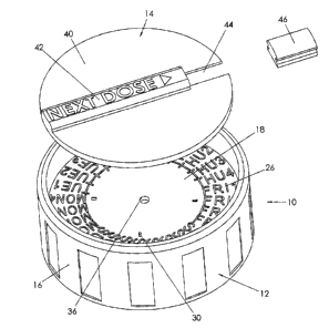
23 [0048] Referring therefore to Figure l, a closure 10 includes a base l2 and
a cover 14. The base
24 12 includes a peripheral wall l 6 that projects to either side of a radial
wall 18. As can best be
2~ seen in Figure 11, the radial wall 18 and peripheral wall 16 define a pair
of oppositely directed
26 counter bores 20. 22. It refill be appreciated that the~counter bore 20 is
configured to match a
27 neck N of a bottle or container shown in ghosted outline. The counter bore
20 may include
28 threads that correspond to the threads on the neck on the container and may
also include a
29 mechanism that inhibits removal of the closure by a child. Such a mechanism
may be of l:noaaw
_6_
CA 02429912 2003-05-28
l construction that requires a combination of rotation and axial movement such
as int~erengagin-~
2 teeth, biased apart normally but which is not been shown in detail in the
drawings.
3 10049] The upper surface 24 of the radial gall l 8 includes an outer band
~of indicia 2b. The
4 indicia 26 indicate a day and a segment of the day at which the next dose of
medi~atinn is dine or
has been taken. Thus in the example shown in Figures 1 and 3, it is
contemplated that the
6 medication evill be taken up to four times per day indicated as, for example
SUN 1, SUN 2, SlJis
7 3, and SUN 4.
[0050] A set of Cam lobes 30 are formed on the upper surface 24 and are
uniformly spaced
9 around the inner circumference of the band 26. As shov~~n in Figure 10. each
lobe 30 has a ramp
32 and an abutment face 34 integrally formed with the ramp 32. In the
embodiment >shown in
11 Figure 1, four cam lobes 30 are disposed around the radially inner
circumference ofband 26.
12 [0051 ] A central retaining hole 36 is provided in the radial face 18 to
secure the coa~~r 14 to the
13 base 12. As seen in Figures 5 and 6, the coe~er 14 includes a bodw 40
f~rm~ed as a circular disk
14 with an upstanding bar 42 integrally moulded on a diameter of the disk 40
to facilitate rotation of
1 j the cover. A radial slot 44 having a radial extent corresponding to that
of the band 26 is formed
l6 in the disc 40 in alignment with the bar 42. The upper surface o:f bar 42
has an indicium
17 indicating "next dose" formed in the surface v~~ith an arrow pointing
toward the slot 44. A lens
18 46 engages with flanks of the slot 44 to pro~Tide a widow in the cover 14.
l 9 [002] The underside of the cover 40 is shown in Figure 6 and has a t-
atchet wheel SO integrally
moulded into the disk 14. The ratchet wheel 50 extends to the edge of the slot
44 and has a set of
2l radial slots 52 defining teeth formed at the periphery of the wheel 50.
22 10053] A retainer 54 projects from the underside centre of the cover 40 and
has a set of resilient
23 tangs 56 shown in greater detail 'in Figure 7 for engagement with the hole
36 in the radial w-all
24 18. Each of the tangs 56 has an enlarged head 58 to pass through the hole
36 and engage in a
counter bore 59 provided in the underside of the re-all 18 to inhibit removal
of the body 40, as can
26 be seen in Figure 12.
2 7 10054] Referring to Figures 9 and l l . the body 40 of the cover 14 is
dimensioned to ~t within
28 the bore 22 and be retained by the retainer 54 on the radial wall I 8. The
slots ~2 of the ratchet
29 wheel 50 accommodate the cam lobes 30 with the abutment face' 34 en~aQino a
radial wall ~f a
slot 52 to inhibit rotation in one direction. The coe er 40 is thus .able to
rotate in a direction in
_-,_
CA 02429912 2003-05-28
1 which the undersurface of the ratchet v~~heel 52 rises over the carn 32 but
couhter rotation is
2 inhibited by the abutment face 34.
3 I00~~] Vhhen assembled, the window 44 is located over the band of indicia 26
~o that a single
4 dosage interval may be viewed through the lens 46: After a dose of
medication has been tai~en,
~ the bar 42 may be used to rotate the disk 40 relative to the base 16 over
the cams 32 until the
6 next slot 52 engages with the cam. The next dosage interval is then
indicated in the window 44.
7 At each dosage, the disk 40 may be incremented one or more times providing
an accurate
8 indication of when the next dose is due: In the event that there is a change
in dose freruency or
9 an interruption of medication, the disk 40 may be easily incremented as many
tines as required
to align the window 44 with the appropriate ipdicium. The recalibration will
often be~ffected in
11 a single s»~eeping action if appropriate torque is exerted on the bar 42.
12 /006] It will be noted that the upper surfaces of the bar 42 and disk 40
are maintained below the
l3 upper edge of the peripheral wall 16 defining the counter bore 22. The
typical spacing between
l4 the upper surface ofthe bar 42, the disk 40 and the top of the wall l6 is
in the order of 2-mm w
although this may be varied depending on particular circumstances. 'The
recessing of the upper
l6 surface of bar 42 and disk 40 below the rim inhibits unintentional movement
of the disk 40
l 7 during removal from, or replacement of, the closure 10 on the container
due to any twisting,
18 turning, squeezing. pushing or other motions or the fingers or palms
required to defeat the
19 childproof mechanisms or to facilitate use by an elderly or arthritic user.
Moreover, as can be
seen from Figure 12, the interaction of the ratchet wheel and the cam 30
prevents rotation of the
21 disk 40 in a counter clockwise direction normally associated v~~ith the
remoe~al of the closure
22 from the container. 'Thus the tendency of the disk 40 to rotate glue to
pressure exerted on the
23 closure 10 to overcome the childproof mechanism is resisted not onl>> by
the rec-essing of the disk
24 but also the orientation of the cams.
2~ 10057] The indicia 26 are shown as integrally moulded into the radial w-all
18 but the indicia may
26 also be applied through printing of the.radial wall 18 or printing on an
adhesive disk that may be
27 inserted into the counter bore 22: In this wav a range of possible dosage
inten~al~s may be
2b incorporated into the closure l6 and the disk incremented past the slots 52
until the next
29 appropriate dosage is visible in the ea-indow- 44. As a further ref nement,
the ratchet wheel 5'0
may be customised for each dosage interval so that the position of the slots
~2 zmresponds to the
_g_
CA 02429912 2003-05-28
l dosages indicated on the indicts 26. It will be appreciated that the lens 46
may be removed to
2 leave an open window 44 to view the indicts.
3 [0058] It will also be noted from Figure 1 I, that the provision of the
ratchet disk 50 maintaips
4 the underside of the disk 40 in spaced relationship from the intlicia in the
band 26 and thereby
inhibits erosion due to rotation between the disk 40 and the surface 18.
6 00059] An alternative embodiment of the closure I 6 is shown in Figures l 3
through l 6 in which
7 like reference numerals are used to indicate like components with a suffix
"a" added for clarity.
8 In the embodiment of Figures 13 through 16. the retainer 56 is replaced by a
semi-circular rabbet
9 60 formed on the radial inner surface of the wall I 6a in the cavity 22a.
The disk 40a has a
diameter greater than that of the bore 22a with a rounded edge complementary
to the semi-
I I circular recess 60. The disk 40a is a snap ft within the recess 60 r~~hich
permits rotation whilst
12 inhibiting separation in an axial direction.
13 [0060] From the foregoing description, it will be recognised by those
skilled in the art that a
.14 medicine reminder device offering advantages over the prior art has been
provided: It is'more
1 ~ economical to manufacture, is compatible with a reside variety ~f existing
anti future child- -
36 resistant mechanisms and provides a reminder mechanism that works in a
~~,~ide variety of dosing
l7 schedules:
l8 10061] In the foregoing specification, the invention has been described
with reference to specific
I 9 preferred embodiments and methods. It will, ho»~ever. be evident to those
of skill in the art that
various modifications and changes may be made without departing from the
broader spirit and
21 scope of the invention as set forth in the attendant claims. The
specification and drawings a~-e.
22 accordingly, to be regarded in an illustrative, rather than restrictive,
sense.
23 f 0062] Although the ine-ention has been described v~~ith reference to
certain speci#ic
2~ embodiments, e~arious modifications thereof will be apparent to those
skilled in the an without
departing from the spirit and scope of the invention as outlined in the claims
appended hereto:
_9_