Note: Descriptions are shown in the official language in which they were submitted.
CA 02430862 2003-06-03
86412-5
1
TITLEe CONTROL PANEL ANI~ CONTROL SYS'T~M FOR A SPA
FIELD OF THE INVENTION
The present invention relates to the field of control systems for spa units;
and more
specifically, to control panels having user interfaces arranged f~r
facilitating use thereof
from different locations.
BACKGROUND OF THE INVENTION
Control panels that are operative to enable a user to control one or more
operational
settings of a spa are known in the art. Typically, such control panels are
placed on the
outer rim of the spa and include a user interface that is arranged to
facilitate operation
by a user located outside the spa. Before entering the spa, a user is able to
use the
control panel in order to set the water temperature and grater jet intensity
for example.
A deficiency with control panels of this type is that they are inconvenient
and difficult
to operate by users located within the spa. More specifically, the positioning
and
orientation of the control panel make the latter difficult to operate by a
user sitting
within the spa. Typically, a user located within the spa ~!nust exit the
comfort of the spa,
at least partially, in order to view the control panel and modify a desired
spa setting.
Against the background described above, it appears th~~t there is a need in
the industry
to provide a control panel for a spa that alleviates at Least in part the
problems
- associated with the existing control panels.
SUMMARY OF THE dNVENTdON
In accordance with a broad aspect, the invention provides a control panel
suitable for
controlling operational settings of a spa. The control panel includes a first
portion
CA 02430862 2003-06-03
86412-5
2
having a first user input device for enabling a user to enter a signal
indicative of a
desired change in a certain operational setting of tl~e spa. The control panel
also
includes a second portion joined to the first portion. The second portion has
a second
user input device for enabling a user to enter a signal indicative of a
desired change in
the same certain operational setting of the spa as the first user input
device. The first
user input device is included within a first user inte;rfacc that is adapted
for being
positioned such as to facilitate use by a user situated in a first location.
The second user
input device is included within a second user interface that is adapted for
being
positioned such as to facilitate use by a user situated in a second location.
l0
In a specific implementation, the first location is located within the spa,
and the second
location is located outside the spa.
In a specific implementation, the first portion and the second portion are
joined together
to form an angle.
In accordance with a first non-limiting implementation, the first portion is
adapted to be
positioned along an inner wall of the spa and the second portion is adapted to
be
positioned along a rim wall of the spa.
In accordance with a second non-limiting implementation, the first portion is
adapted to
be positioned along a rim wall of the spa, and the second portion is adapted
to be
positioned along an outside wall of the spa.
In accordance with a third non-limiting implementation., the first portion and
the second
portion are joined via a third portion. The first portion is adapted to be
positioned along
an inner wall of the spa and the second portion is adapted to be positioned
along an
outer wall of the spa.
In specific implementations, the portion of the control panel adapted to
positioned along
3~ an inner wall of the spa shell may be recessed from the inner wall, may
protrude from
the inner wall, may be substantially aligned with the inner wall or may be
positioned at
CA 02430862 2003-06-03
86412-5
3
an angle with respect to the inner wall without detracting from the spirit of
the
invention. When a portion of the control panel is positioned at an angle with
respect to
the inner wall, the angle will generally be between about 0 degrees and about
45
degrees in either direction from the surface of the inner wall. Similarly, the
portion of
the control panel positioned along a rim wall of the spa may be recessed from
the rim
wall, may protrude from the rim wall, may be substantially aligned with the
rim wall or
may be positioned at an angle with respect to the rim wall without detracting
from the
spirit of the invention. When a portion of the control is positioned at an
angle with
respect to the rim wall, the angle will generally be between about 0 degrees
and about
l0 45 degrees in either direction from the surface of the r:im wall. In
addition the portion
of the control panel positioned along an outer wall of tlae spa may be
recessed from the
outer wall, may protrude from the outer wall, rnay b~e substantially aligned
with the
outer wall or may be positioned at an angle with respect to the outer wall
without
detracting from the spirit of the invention. When a portion of the control is
positioned
at an angle with respect to the outer wall, the angle will generally be
betwcen about 0
degrees and about 45 degrees in either direction from the starface of the
outer wall.
In accordance with a specific example, the first user interface and the second
user
interface include multiple user input devices for enabling a user to control
multiple
operational settings of the spa. The user input devices on the first user
interface and the
user input devices on the second user interface are adapted to control a same
set of
operational settings of the spa or, alternatively are adapted to control
different sets of
operational settings of the spa.
In accordance with a broad aspect, the invention provides a control system
suitable for
controlling operational settings of a spa. The control system includes a fzrst
portion
having a first user input device for enabling a user to enter a signal
indicative of a
desired change in a certain operational setting of the spa. The control system
also
includes a second portion joined to the first portion. The second portion has
a second
3o user input device for enabling a user to enter a signal indicative of a
desired change in
the same certain operational setting of the spa as the first user input
device. The control.
CA 02430862 2003-06-03
86412-5
4
system also includes a control entity in communication: with the first user
input device
and the second user input device for receiving signals indicative of desired
changes in
the certain operational setting of the spa. The control entity is responsive
to a signal
received from either one of the first user input device and the second user
input device
for causing the desired change in the certain operational setting of the spa
to be
implemented.
In a specific implementation, the control entity is in wire-line communication
with
either one or both of the first user input device and the second user input
device.
In another specific implementation, the control entity is in wireless
communication with
either one or both of the first user input device and the second user input
device. In a
non-limiting implementation, the control entity communicates with either one
or both of
the first user input device and the second user input device over either one
of an radio
frequency (RF) link or an infra-red IR link.
In a specific implementation, the first portion includes a first user
interface where the
first user input device is part of the first user interface. In addition, the
second portion
includes a second user interface where the second userinput device is part of
the second
2o user interface. The first user interface is adapted to be positioned such
as to facilitate
use by a user situated within the spa and the second user interface is adapted
to be
positioned such as to facilitate use by a user situated outside the spa.
In accordance with another broad aspect, the invention provides a spa system
including
a spa shell, a comfort component and a control system mounted to the spa
shell. The
control system adapted for causing the generation of signals directed to the
comfort
component for controlling an operational setting of the spa. The control
system
includes a control panel and a control entity. The control panel includes a
first portion
having a first user input device for enabling a user to enter a signal
indicative of a
desired change in the operational setting of the spa. T'he control panel also
includes a
second portion joined to the first portion and having a second user input
device for
CA 02430862 2003-06-03
X6412-5
enabling a user to enter a signal indicative of a desired change in the same
operational
setting of the spa as the first user input device. The control entity is in
communication
with the first user input device and the second user input device for
receiving signals
indicative of desired changes in the operational setting of the spa. The
control entity is
5 responsive to a signal indicative of a desired change in the operational
setting of the spa
received from either one of the first user input device and the second user
input device
for causing the desired change in the operational setting of the spa to be
implemented.
In accordance with another broad aspect, the invention provides a control
panel suitable
for controlling operational settings of a spa. The control panel includes a
first portion
and a second portion. The first portion has a first user interface including a
first user
input device for enabling a user to enter a signal indicative of a desired
change in a
certain operational setting of the spa. The second portion is joined to the
first portion
and has a second user interface for conveying information related to the
certain
operational setting of the spa. The first user interface is positioned to
facilitate use by a
user situated in a first location, and the second user interface is positioned
such as to
facilitate use by a user situated in a second location.
In a specific implementation, the second user interface incltades a display
screen for
displaying information indicative of the certain operational setting of the
spa.
Alternatively, the second user interface includes an an.dio output device for
issuing an
audio signal conveying the certain operational setting of the spa.
In accordance with yet another broad aspect, the invention provides a control
panel
suitable for controlling an operational setting of a spa. The control panel
includes a first
portion having first means for enabling a user to enter a signal indicative of
a desired
change in the operational setting of the spa. The control panel also includes
a second
portion joined to the first portion. The second portion has second means for
enabling a
user to enter a signal indicative of a desired change in the same operational
setting of
the spa at the first means. The first means is adapted for being positioned
such as to
CA 02430862 2003-06-03
86412-5
6
facilitate use by a user situated in a first location, and the second means is
adapted for
being positioned such as to facilitate use by a user situated in a second
location.
BRIEF DESCRIPTI~1V ~F TIIE DR,~ SINGS
A detailed description of examples of implementation of the present invention
is
provided hereinbelow with reference to the following drawings, in which:
Figure 1 shows a spa equipped with a control panel iri accordance with a first
specific
to example of implementation of the present invention;
Figure 2 shows an enlarged view of the control panel shown in Figure 1;
Figure 3 shows a specific example of a control panel in accordance with a
second
example of implementation of the present invention;
Figure 4 shows the control panel shown in Figure 1 positioned in a different
configuration on a spa, in accordance with a specific example of
implementation of the present invention;
Figure 5A shows a spa equipped with a control panel in accordance with a third
specific
example of implementation of the present invention;
Figure SB shows a spa equipped with a control panel in accordance with a
fourth
specific example of implementation of the present invention;
Figure 5C shows a spa equipped with a control panel in accordance with a fifth
specific
example of implementation of the preserdt invention;
Figures 5I3 and 5E show a spa equipped with a control panel in accordance with
a sixth
specific example of implementation of the present invention;
CA 02430862 2003-06-03
86412-5
7
Figure SF shows a spa equipped with a control panel in accordance with a
seventh
specific example of implementation of the present invention;
Figure 6 shows the control panel from Figure 1 in communication with a control
entity,
in accordance with a specific example of implementation of the present
invention;
Figure 7 shows a block diagram of a computing unit for implementing the
functionality
of the control entity shown in Figure 6;
Figures 8A, 8B, 8C, 8D, 8E, 8F show a specific example of a control panel in
accordance with an eighth example of implementation of the present
invention.
In the drawings, embodiments of the invention are illustrated by way of
example. It is
to be expressly understood that the description and drawings are only for the
purposes
of illustration and as an aid to understanding, and are not intended to be a
definition of
the limits of the invention..
DETAILED DESCIZ11'TI~N
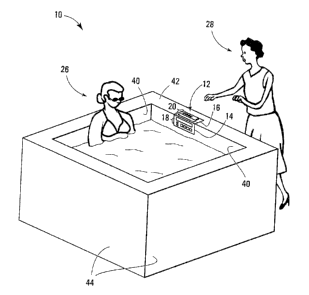
Shown in Figure 1 is a spa IO that is equipped with a control panel 12 in
accordance
with a specific example of implementation of the present invention. The
control panel
12 is operative to enable a user to control at least one operational setting
of the spa.
It should be understood that the term "spa", as used for the purposes of the
present
description, refers to spas, whirlpools, hot tubs, bath tubs, swimming pools
and any
other type of bathing receptacle that can be equipped with a control panel for
3o controlling various operational settings. Some non-limiting examples of
operational
settings of the spa include an on/off setting, a temperature control setting,
jet control
CA 02430862 2003-06-03
86412-5
8
settings and lighting settings. It should also be appreciated that, where the
spa is
connected to entertainment and/or multimedia modules, the operational settings
of the
spa may also include audio settings and video settings amongst others.
Consequently,
the expression "operational settings'' for the purpose of the present
invention is intended
to cover operational settings for any suitable equipment that can be used by
the spa
bather.
As shown in Figure l, the control panel 12 includes a first portion 14, and a
second
portion 16 that is joined to the first portion 14. As can best be seen in the
enlarged view
to of control panel 12 shown in Figure 2, the first portion 14 includes a
first user interface
18, and the second portion 16 includes a second user interface 20. Both the
first user
interface 18 and the second user interface 20 include user input devices 21.
The user
input devices 21 enable a user to enter signals indicative of desired changes
in the
operational settings of the spa. In the specifac control panel 12 depicted in
figure 2, the
user-input devices are shown as buttons forming keypads 22. In addition, in
the
example shown in figure 2 both the first user interface 18, and the second
user interface
20, include a display screen 24.
It should be understood that the physical implementations of user interfaces
18 and 20
can vary greatly without departing from the spirit of the invention. For
example, the
user interfaces 18 and 20 are not limited to including a keypad 22 and instead
can
include any combination of user input devices, such as levers, toggle
switches,
keyboard, touch sensitive screen, microphone connectc;d to a voice recognition
unit, an
infra-red receiver for receiving signal from a remote control device or any
other suitable
user input devise known in the art for allowing an operator to enter commands
relating
to the operational settings of the spa. In addition, the display screens 24
are optional
components for user interfaces 18 and 20.
In an alternative physical implementation (shown figure SF of drawings), at
least some
user-input devices may be shared between the first user interface 18 and the
second user
interface 20. In a first specific example of such an alternative physical
implementation,
CA 02430862 2003-06-03
X6412-5
9
user interfaces 18 and 20 intersect along an edge and the input devices are
located along
that edges such as to be conveniently accessed from two different locations.
In a second
specific example of such an alternative physical ianplementation, the first
interface
includes a set of user-input devices in the form of switches. The second user
interface
includes second input devices in the form of mechanical levers adapted to
actuate the
user-input devices in the first user interface such that; the user-input
devices Located on
the first user interface are accessible from the first user interface and the
second user
interface.
to In another alternative physical implementations (not shown in the
drawings), the user
input devices may be omitted from either one of thc~ first user interface 18
or second
user interface 20. In such alternative physical implementations, the user
interface
without user input devices is adapted for conveying information related to the
operational settings of the spa. This may be effected through any suitable
output device
including without being limited to a display screen, a set of one or more
LEI3s, an audio
output device such as a speaker or any other suitable output device known in
the art for
conveying to a user information related to the operational settings of the
spa. The output
device may be controlled by any suitable device driver. Such device drivers
are well
known in the art and as such will not be described fur~~her here.
As will be described in more detail further on, in a specific implementation,
at least one
operational setting of the spa can be controlled fromboth the first user
interface I 8 and
the second user interface 20. For example, both the first user interface 18
and the second
user interface 20 include a user input device that is operative to control the
same
operational setting of the spa. Advantageously, this allows a user to control
at least one
operational setting of the spa from both the first user interface 18 and the
second user
interface 20. For example, both the first user interface 18 and the second
user interface
20 can include an on/off button that is able to turn the spa on and off.
3o It should also be understood that user interfaces 18 and 20 can include any
number of
user input devices in order to enable a user to control any number of
operational settings
CA 02430862 2003-06-03
86412-5
of the spa. For example, the user interfaces 18 and 2t) may include only one
user input
device, such as a single button, for enabling a user. to control only one
operational
setting of the spa, such as an on/off setting. Alternatively, the one user
input device
could be a touch sensitive screen or microphone, through which the user can
control
5 multiple operational settings of the spa. In the example shown in Figure 2,
the user
interfaces 18 and 20 include a number of user input devices, in the form of
buttons 21,
in order to enable a user to control multiple operational settings of the spa.
More
specifically, each button 21 corresponds to a different operational setting.
Alternatively, an operational setting selection input is provided such as to
allow a same
l0 button to correspond to multiple operational settings depending on the
operational
setting selected by the operational setting selection input.
Referring back to Figure l, it is shown that the first user interface 18 is
arranged to
facilitate use by a user 26 situated in a first location, and the second user
interface 20 is
15 arranged to facilitate use by a user 28 situated in a second location. In
the specific
example of implementation shown in Figure 1, the ~zser 26 situated in the
first location
is situated within the spa 10, and the user 28 situated in the second location
is sihzated
outside the spa 10. As such, any symbols or text included an the first user
interface 18,
either to identify buttons on the keypad 22 or displayed on the display screen
24, are
20 arranged to facilitate reading by user 26 located in the spa. Likewise, any
symbols or
text included on the second user interface 20, are arranged to facilitate
reading by user
28 located outside the spa. In this way, regardless of whether a user is
located within the
spa, or outside the spa, the user is not forced to adopt an uncomfortable
position in order
to be able to easily read text or symbols displayed on a user interface of the
spa.
25
In the specific example of control panel 12, the first user interface 18 is
substantially the
same as the second user interface 20, thereby providing user 26 located within
the spa
with the same functionality as user 28 located outside the spa. The second
user interface
includes substantially the same user input devices as the first user interface
18 such
30 that a user is able to enter substantially the carne commands indicative of
desired
changes in the operational settings of the spa at the first user interface 18
and at the
CA 02430862 2003-06-03
86412-S
11
second user interface 20.. For example, for each operational setting that can
be
controlled via the second user interface 18, the same operational setting can
be
controlled via the first user interface 20. More speei~cally, the first user
interface I8
includes a first set of user input devices adapted for enabling a user to
control a set of
operational settings of the spa. The second user interface 20 includes a
second set of
user input devices adapted for enabling a user to control the same set of
operational
settings of the spa as the first set of user input devices. This allows a user
to cause
desired changes in the same set of operational settings of the spa at the
first user
interface and at the second user interface.
It should be understood that in alternative examples of implementation, the
functionality
provided by the first user interface 18 is different from. the functionality
provided by the
second user interface 20. For example, an operational setting that can be
controlled via
one user interface may not be controlled via the other user interface.
Shown in Figure 3 is a control panel 30 that includes a first portion 32
having a first
user interface 34, and a second portion 36 having a second user interface 38.
In this
non-limiting example, the second user interface 38 includes more user input
devices 37
than the first user interface 34. As such, the second user interface 38
enables a user to
control different operational settings of the spa from those controllable from
the first
user interface 34. For example, the second user interface 38 includes at least
one user
input device 37 that enables a user to enter a signal indicative of a desired
change in an
operational setting at the second user interface 38 that the user is not able
to enter at the
first user interface 34. More specifically, the first user interface 34
includes a first set of
user input devices adapted for enabling a user to control a first set of
operational
settings. The second user interface 38 includes a second set of user input
devices
adapted for enabling a user to control a second set of operational settings.
The second
set of operational settings including at least one operational setting absent
from the first
set of operational settings such as to allow a user to cause desired changes
in different
3o sets of operational settings of the spa at the first user interface and at
the second user
interface. It should be understood that in an alternative embodiment, the
second user
CA 02430862 2003-06-03
86412-5
12
interface 38 might have a reduced functionality compared to the first user
interface 34.
Control panels in accordance with the present invention, such as control
panels 12 and
30 described above, are adapted to be positioned on spas of the type shown in
Figure l,
such that the two user interfaces are arranged to facilitate use by users
Located in
different positions. In addition, in accordance with a non-limiting
implementation, the
control panels may be installed on a spa shell using a single hole punctured
in the shell
of the spa. This facilitates ease of installation, and also reduces the
likelihood of leaks
that are caused by having multiple holes punctured in the shell of the spa.
Spa 10, shown in Figure 1, includes a spa shell having four inner walls 40, a
rim wall 42
and four outer walls 44. It should, however, be ur.~derstood that control
panels in
accordance with the present invention can be installed on spa shells having
any number
of inner and outer walls made in any shape and size. For example, many spa
shells
1 s include more or less than four inner walls 40, and have inner walls 40
that are angled
and/or curved. The same thing is true of the outer walls 44. Many spa shells
include
more or less than four outer walls 44, and have outer walls 44 that are angled
and
curved. The term "rim wall" as used for the purposes of the ;present
invention, can be
any wall that acts to join the inner walls 40 with the outer walls 44. The rim
wall 42 can
2o be curved, angled or molded into any suitable shape.
In a specific implementation, the control panel is mounted to the spa shell
such that one
portion of the control panel is positioned to be accessed from inside the spa
and the
other portion is positioned to be access from outside the spa. The control
panel may be
25 flush with the spa shell, may protrude from spa shell or may be recessed
from the spa
shell without detracting from the spirit of the invention.
The first portions and second portions can be joined in a variety of different
configurations. In a first specific configuration, the first portions and
second portions
3o are adapted to straddle the spa shell. Ln a second specific configuration,
the first
portions and second portions are part of a control panel body adapted to be
positioned in
CA 02430862 2003-06-03
86412-5
13
a recessed portion of the spa shell. In a third specific configuration, the
first portions
and second portions are part of a control panel body adapted to be positioned
atop a rim
wall of the spa shell. A few, specific, non-limiting examples of how the first
portions
and second portions can be joined will be described in more detail below.
As shown in Figure 2, the first portion 14 and the second portion 16 of
control panel 12
are joined at an angle a corresponding essentially to the angle formed between
the rim
wall and the inner wall where the control panel 12 is to be installed. In
figure 2, this
angle is shown as being an angle of about 90 ° . As such, in the
configuration shown in
l0 Figure 1 the control panel 12 is able to be positioned on the spa IO such
that the first
portion 14 is positioned along an inner wall 40 of the spa, and the second
portion 16 is
positioned along a rim wall 42 of the spa. In Figure 4, control panel 12 is
shown
positioned on spa 10 in a different configuration, wherein the first portion
14 is
positioned along a rim wall 42 of the spa and the second portion 16 is
positioned along
an outer wall 44. In both of these configurations, the first user interface I8
is arranged
to facilitate use by a user situated within the spa and the second user
interface 20 is
arranged to facilitate use by a user situated outside the spa.
As for control panel 30 shown in Figure 3, the first portion 32 and the second
portion
36, are also joined at an angle a of about 90 ° , such that the control
panel 30 can be
positioned on spa 10 in the same types of configurations as described above
with
respect to control panel I2.
Shown in Figure 5A is a control panel 50 in accordance with a third specific
example of
implementation of the present invention. Control panel 50 includes a first
portion 52
having a first user interface 56, and a second portion ~4 having a second user
interface
58. The first portion 52 and the second portion 54 are joined at an angle (3,
such that the
control panel 50 can fit properly on a spa shell having an angled inner wall,
such as spa
51 shown in Figure 5A. It should be understood that the first portion 52 and
the second
3o portion 54 can be joined at any angle (3 that permits the two portions of
the control panel
50 to be positioned along a combination an inner wall and a rim wall of a spa
or a rim
CA 02430862 2003-06-03
86412-5
14
wall and an outer wall of a spa. In a sped frc embodiment of control panel 50,
angle (3 is
an angle between about 45 ° and about 170 ° . In the example
shown in figure Sa,
angle (3 is an obtuse angle. In an alternative example, the angle j3 may be an
acute angle
allowing the control panel to be positioned along a combination an inner wall
and a rim
wall of a spa shell or a rim wall and an outer wall of a spa shell forming an
acute angle.
Shown in Figure SB is a control panel 60 in accordance with a fourth specific
example
of implementation of the present invention. Control panel 60 includes a first
portion 62
having a first user interface (not shown), and a second portion 64 having a
second user
to interface 66. The first portion 62 and the second portion 64 are joined
together via a
third portion 68. As such, control panel 60 can be positioned on the spa such
that the
first portion 62 is positioned along an inncr wall of the spa shell and the
second portion
64 is positioned along an outer wall of the spa shell. In this configuration,
the first user
interface (not shown) is arranged to facilitate use by a user situated within
the spa and
the second user interface 66 is arranged to facilitate use by a user situated
outside the
spa.
A control panel 70 in accordance with a fifth specific example of
implementation of the
present invention is shown in Figure SC. Control panel 70 includes a first
portion 72
2o having a first user interface 76 and a second portion 74 having a second
user interface
78. 'The first portion 72 and the second portion 74 are joined together by
body 79.
Control panel 70 is adapted to be positioned on spa 10 such that the first
user interface
76 is arranged to facilitate use by a user situated within the spa and the
second user
interface 78 is arranged to facilitate use by a user situated outside the spa.
A control panel 600 in accordance with a sixth specific example of
implementation of
the present invention is shown in Figure 5D. Control panel 600 includes a
first portion
614 having a first user interface 618 and a second portion 616 having a second
user
interface 620. The first portion 614 and the second portion 61.6 are joined
together by
3o body 500. Control panel 600 is adapted to be positioned in a recessed
portion of the spa
shell. In the example shown in figure SD, the first portion 614 of the control
panel 600
CA 02430862 2003-06-03
86412-5
is positioned along an inner wall 40 of the spa shell. It will be appreciated
that the first
portion 614 may be recessed from the inner wall, ma.y protrude from the inner
wall,
may be substantially aligned with the inner wall or may be positioned at an
angle with
respect to the inner wall without detracting from the spirit of the invention.
~Ihen the
5 portion 614 of the control panel 600 is positioned at an angle with respect
to the inner
wall 40, the angle will generally be between about 0 degrees and about 45
degrees in
either direction from the surface of the inner wall. Figure 5E of the drawings
illustrates
a side elevation of control panel 600 positioned such that the first portion
614 of the
control panel 600 is positioned along the inner wall 400, recessed therefrom
and at an
1 o angle "m" with respect to the inner 'vall.
A control panel 700 in accordance with a seventh specific example of
implementation
of the present invention is shown in Figure SF. Control panel 700 includes a
first
portion 718 and a second portion 716. At least some user-input devices 722 are
shared
15 between the first user interface and the second user interface. As shown,
the first portion
and the second portion intersect along an edge and the input devices 722 are
located
along that edge such as to be conveniently accessed frown two different
locations.
A control panel 800 in accordance with a eighth specific example of
implementation of
2o the present invention is shown in figures 8a, 8b, 8c, 8d, 8e and 8f. Figure
8a shows a
front elevation view of the control panel 800. Figure 8b shows a top plan view
of the
control panel 800. Figure 8c shows a rear elevation view of the control panel
800.
Figure 8d shows a side elevation view of the control panel 800. Figure 8e
shows a
perspective view of the control panel 800. Figure 8f shows a bottom view of
the control
panel 800. Control panel 800 includes a first portion 1314 having a first user
interface
and a second portion 816 having a second user interface. The first portion 814
and the
second portion 816 are joined together by a body. Control panel 800 is adapted
to be
positioned either in a recessed portion of the spa shell or atop the spa
shell. The first
portion 814 and the second portion 816 form an angle 0 there between. The
angle 8 can
be of any suitable value. In a non-limiting implementation, the angle 0 is
between about
45 degrees and about 170 degrees. The first user interface and second user
interface
CA 02430862 2003-06-03
86412-5
16
include respective display screens 860 and 850 for <;onveying information
regarding
operational settings of the spa. The first user interface and second user
interface also
include respective input devices 822 for enabling a spa user to provide
commands for
modifying operational settings of the spa.
It should be understood that the above described control panels are specific,
non
limiting examples of implementation of control panels in accordance with the
present
invention, and that other embodiments and configurations of control panels in
accordance with the present invention can be envisaged by the person skilled
in the art
in light of the present specification.
Referring now to Figure 6, control panel 12 is shown in communication with a
control
entity 80 for implementing the desired changes to the operational settings of
the spa, as
entered by the user via the first user interface 18 and the second user
interface 20.
Although control panel 12 will be used for the purposes of the following
description, it
should be understood that any one of the control panels 30, 50, 60 or 70
described
above are also adapted to be used in conjunction with a control entity 80.
The control entity 80 is in communication with the user input devices of the
first user
interface and the user input devices of the second user interface for
receiving signals
indicative of desired changes in the certain operational setting of the spa.
The control
entity 80 is responsive to a signal received from a user input device in
either one of the
first user interface and the second user interface indicative of a desired
change in the
certain operational setting of the spa for causing the desired change in the
certain
operational setting of the spa to be implemented. ~ptionally, control entity
80 is also in
communication with either one or both of the first user interface and second
user
interface for issuing control signal for controlling output devices, such as a
display
screen, LEDs or speaker, for conveying information related to an operational
setting of
the spa.
The control entity 80 may be part of the control panel 12 or may be part of a
centralized
CA 02430862 2003-06-03
86412-S
17
control system adapted for controlling various spa components. As such the
control
entity may be positioned in proximity to the control panel 12 or remotely
therefrom
without detracting from the spirit of the invention. In addition, the
functionality
implemented by control entity 80 may be implemented i.n one or more processors
and/or
micro-controllers which may be distributed in different physical locations or
which may
be positioned in a same location. In a non-limiting implementation, control
entity 80 is
part of a spa control pack and is positioned remotely from the control panel
12.
However, other possible mounting positions for control entity 80 can also be
used
without departing from the spirit of the invention.
to
In the specific embodiment shown in Figure 6, control entity 80 is in
communication
with the user inputs of the first and second portions 14 and 16, which in the
case of
control panel 12 are the buttons of keypads 22, via a communication link. The
communication link may be any suitable link such as a wireline link, an
infrared link, a
radio frequency link or other suitable wireless links.
In order to cause the desired changes in the operational settings to be
implemented, the
control entity is in communication with actuators that. are operable to
implement the
desired changes in the operational setting by selectively actuating comfort
components.
2o Such actuators may be in the form of relays and solid-state switches for
example.
Comfort components may include without being limiting to a heating element,
pump,
blower, valve, ozonator, sanitization system, a lighting elememt, audio
equipment video
equipment and computer equipment. The computing unit 80 includes the suitable
logic
far receiving and processing a command indicative of a desired operational
setting for
the spa such as to generate appropriate signals for causing the operational
settings to be
set to the desired values. For example, in the case where the command is
indicative of a
desire to have the temperature in the water increased, the control entity 80
issues a
signal to a heating element to cause the temperature of the water to be
increased to the
desired temperature. The manner in ~~hich the water temperature is set to a
desired
3o temperature may be effected in any manner well known in the art and as such
will not
be described further here. The example of increasing the temperature of the
water is
CA 02430862 2003-06-03
86412-5
18
simply being used for the purposes of illustration, and it should be
understood that any
other controllable function of the spa could also have been used for the
purposes of this
description. Optionally, the computing unit 80 includes the suitable logic for
issuing
signals to either one or both of the first user interface and second user
interface for
causing output devices, such as a display screen, LEDs or spealker, to
conveying
information related the temperature of the water such as the desired water
temperature,
the actual water temperature or both.
The computing unit 80 may be configured as a computing apparatus 90 of the
type
depicted in Figure 7, including a processing unit 92 and a set of interfaces
102 702 and
104 for receiving or sending data elements to external devices. The processing
unit 92
is adapted to implement the desired changes in the operational settings as
described in
the specification. For example, interface 102 receives/transmits signals the
first user
interface of the control panel described above. Interface 702
receives/transmits signals
the second user interface of the control panel 12 described above. The
processing unit
92 is operative for processing the signals received from either interface 702
or 102 to
derive local signals for transmission to the actuators, in order to have the
desired change
in the operational setting implemented. Interface 104 is for releasing the
local signals to
the actuators for causing the desired changes to be implemented. The
processing unit
92 is operative for issuing signals directed to either interface 702 or 102 or
both to cause
the user interfaces through suitable output devices to convey information
related to
operational setting of the spa. In a non-limiting implementation, the
processing unit 92 is
operative for issuing signals directed to an output driver module associated
to the
control panel interfaces. In the case where the user interfaces include a
display, the
interface 102 and 701 are adapted for releasing signals to display drivers
associated to
the user interfaces of the control panel for causing the display to convey
information
related to operational setting of the spa. Where the control panel is of the
type shown in
figure 6, the interface 702 may cause the same information to be conveyed by
the first
portion 14 of the control panel and by the second portion 16. Alternatively,
the interface
702 may cause different information to be conveyed by the first portion 14 of
the control
panel and by the second portion 16 of the control panel.
CA 02430862 2003-06-03
86412-5
19
As mentioned earlier, in use, a user uses the user input devices located on
either one of
the first and second portions of the control panels ~.n order to input a
command
indicative of a desired change in an operational setting of the spa. For
example, in the
case of control panel 12 shown in figure 6, the first user interface 18 of the
first portion
14 includes a button 88 for enabling a user to increase the temperature of the
water in
the spa. Similarly, the second user interface 20 of the second portion 16
includes a
button 89 that is also for enabling a user to raise the tennperature of the
water in the spa.
As such, a user can use either one of buttons 88 or 89 in order to enter a
command for
causing the temperature of the water to be increased.
The control entity 80 is responsive to a signal indicative of the command to
increase the
temperature of the water originating from either button 88 or 89, for causing
the desired
change in the water temperature to be implemented.
Although the present specification has described embodiments of the invention
having a
control panel with two portions, it will be appreciated that the control panel
may be
comprised of two or more portions for facilitating usage thereof from multiple
locations.
Although various embodiments have been illustrated, this was for the purpose
of
describing, but not limiting; the invention. Various modifications will become
apparent
to those skilled in the art and are within the scope of this invention, which
is defined
more particularly by the attached claims.