Note: Descriptions are shown in the official language in which they were submitted.
CA 02431688 2003-06-11
WO 02/074381 PCT/USO1/47568
IMPLANTABLE REFILLABLE AND PORTED CONTROLLED
RELEASE DRUG DELIVERY DEVICE
Technical Field
The present invention relates to infusion systems implantable in a mammalian
body to
administer a drug. More particularly, the present invention relates to a
subcutaneously
implantable direct delivery access port permitting multiple intermittent
injections, which may
be used in combination with a subcutaneous drug infusion apparatus, such as a
catheter, and at
least one rate-limiting permeable membrane to regulate drug delivery.
Background
To overcome some of the disadvantages of repeated venipuncture injections,
implantable infusate injection ports were developed. Such devices provide a
bolus or
therapeutic dose of the drug contained therein to a particular location within
the patient's body.
To replenish the drug in the implanted device, a subcutaneous device can be
provided in fluid
communication with the drug delivery device, such as provided in U.S. Patent
No. 5,137,529,
incorporated herein by reference. These implantable devices typically include
an internal
chamber, a penetrable self sealing septum, and a hollow male outlet connector,
which are
subcutaneously implanted within the patient.
The outlet connector is attached to a catheter element or drug delivery tube
for
transmitting drugs from the internal chamber to a predetermined area of the
patient's body, such
as a cavity, a large vein, a tumor, or an injury site. Once installed, the
internal chamber can be
periodically filled with drug by inserting a hypodermic needle through the
patient's skin and the
septum to permit injection of the drug into the internal chamber. Devices of
this general type
can be effectively utilized for dispensing drug in the body of a patient over
a prolonged period
CA 02431688 2003-06-11
WO 02/074381 PCT/USO1/47568
of time since the injection port provides a means for administering additional
medicament into
the device by means of a syringe inserted into the injection port.
Typically, such devices utilize pumps of one form or another. That is, they
are
designed to pump the drug from a reservoir through a tube to a site in the
body. One of the
disadvantages of such systems is that there is a net change in volume in the
reservoir and/or the
receptor. This net change in volume is undesirable where, for example, a drug
is being
delivered to an area such as the brain where slight volume changes can cause a
large change in
intracranial pressure.
Another problem encountered by conventional devices is device leakage. U.S.
Patent
4,857,053 to Dalton, for example, discloses that drug delivery ports utilizing
elastomeric
materials, such as silicon rubber, as the penetrable wall material tend to
develop leaks.
Therefore, a need exists for an implantable, refillable, rate controlled leak-
proof drug
delivery device that does not rely on pressure to drive a drug from the
device.
Summary Of The Invention
An advantage of the present invention is an implantable and refillable drug
delivery
device utilizing a septum that substantially prevents leakage.
Another advantage of the present invention is an implantable and refillable
drug
delivery device utilizing at least one rate-limiting permeable membrane that
passively regulates
drug delivery.
According to the present invention, the foregoing and other advantages are
achieved in
part by an implantable, refillable, rate controlled drug delivery device. The
device includes a
base structure having at least a first opening and a second opening, the base
structure defining a
chamber; a septum covering the first opening and configured to substantially
prevent leakage
CA 02431688 2003-06-11
WO 02/074381 PCT/USO1/47568
from the first opening to an exterior of the device; a drug delivery tube
communicating with the
chamber through the second opening, and at least one rate-limiting permeable
membrane
disposed within said drug delivery tube, which membrane passively regulates
drug delivery.
In accordance with the present invention, the foregoing and other advantages
are also
achieved in part by a method of controlling the delivery of a drug to an
internal portion of a
body by administering a drug to an internal portion of the body through the
device according to
the present invention to control the delivery of the drug.
Additional advantages of the present invention will become readily apparent to
those
skilled in the art from the following detailed description, wherein
embodiments of the invention
are described simply by way of illustrating of the best mode contemplated in
carrying
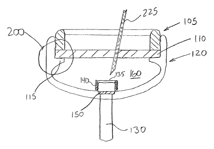
Brief Description Of The Drawings
FIG. 1 shows a cross-sectional view of a device in accordance with the present
invention.
FIG. 2 shows an assembled device in accordance with the present invention.
FIG. 3 shows a cross-sectional view of another embodiment of a device in
accordance
with the present invention.
FIG. 4 is a cross-section of a further embodiment of the device of the present
invention.
FIG. 5 is a cross-section of yet another device in accordance with the present
invention.
FIGS. 6a and 6b show non-limiting configurations of the rate-limiting
permeable
membrane in accord with the invention.
CA 02431688 2003-06-11
WO 02/074381 PCT/USO1/47568
Description Of The Invention
As shown in the appended figures, the present invention provides an
implantable,
refillable, rate controlled drug delivery device, generally designated in the
respective figures by
the reference number 100. FIG. 1 shows device 100 comprising an elastomeric
perforatable
septum 110, a lower base structure 120, a catheter or drug delivery tube 130,
a retaining ring
105 provided to retain septum 110 in place, and rate-limiting permeable
membrane 150
disposed across an opening 145 in the lower base structure in communication
with drug
delivery tube 130.
The perforatable septum 110 defines, in conjunction with the lower base
structure 120,
a chamber or reservoir 160 in which a drug may be stored. Optionally, a filter
housing 135
having one or more filter elements 140 may be provided between the reservoir
160 and the rate-
limiting permeable membrane 150. An upper portion of the filter housing 135
may comprise a
needle stop. A needle stop presents a barrier to passage of the needle and
prevents the needle
from passing through the upper portion to the rate-limiting permeable membrane
150 where it
could contact and damage the rate-limiting permeable membrane. To protect the
filter elements
140, the filter elements may be disposed beneath the housing 135 or may be
disposed
substantially perpendicular to the septum 110 so that a needle pushed
perpendicularly through
the septum to contact the inner wall of the base structure 120 would not
contact the filter
elements 140. Alternatively, filter elements 140 may be arranged in a tapered
configuration
extending from the needle stop portion of the filter housing 135. The filter
housing 135 itself
may take many forms, such as, but not limited to, a substantially rectangular
or hemispherical
structure. Alternatively, the filter housing 135 may simply comprise a needle
stop, such as a
perforated plate having a plurality of perforations of a diameter smaller than
the smallest
expected needle diameter. This needle stop would permit insertion and
securement of a simple
hemispherical filter element about the rate-limiting permeable membrane.
4
CA 02431688 2003-06-11
WO 02/074381 PCT/USO1/47568
Drug delivery tube 130 is attached, by conventional means such as, but not
limited to,
an interference fit, adhesive connection, or microferrule connection to lower
base structure
opening 145. This drug delivery tube 130 may itself be a catheter or may
comprise a
connector, known to those skilled in the art, for a catheter or another form
of drug delivery
tube. The drug delivery tube may take many conventional forms. As shown, one
of these
forms includes a tube 130 having a central passage and a closed end 137.
Perforations 138
through the wall at one or more desired sites provide for fluid communication
between the
central passage and the outside of the tube at the sites.
Opening 145 may be provided at other locations within reservoir 160 and may
advantageously be located in a side wall thereof to facilitate placement in
other orientations and
locations within a patient. In this regard, it is noted that the shape of
lower base structure 120
in FIG. 1 is only one representative structure and is non-limiting. For
example, the base
structure may be specifically configured for placement in various areas of the
body and may
also include tabbed portions on an exterior thereof to facilitate securement
of the base structure
to, for example, bones or tissue. The outer surface of the lower base
structure 120 could, for
example, have a substantially planar bottom, a convex bottom, or a concave
bottom. The inner
bottom surface of lower base portion 120 does not have to correspond to the
outer surface of
the lower base structure, but may so correspond to minimize weight and cost.
As shown in
FIG. 1, the inner bottom surface of lower base portion 120 is gently curved
between the
opening 145 and the septum ledge 115. This curvature helps prevent stagnation
of fluid within
the reservoir 160.
Although the rate-limiting permeable membrane 150 is shown in FIG. 1 as
occupying a
position across opening 145, the rate-limiting permeable membrane may be
disposed in any
position so long as it is permitted to control the rate of drug delivery to
the target area of drug
delivery by diffusion. Namely, the rate-limiting permeable membrane 1 SO is
disposed across a
CA 02431688 2003-06-11
WO 02/074381 PCT/USO1/47568
passage between the base structure 120 and a distal end of drug delivery tube
130 such that the
rate-limiting permeable membrane 150 passively regulates drug delivery. The
passage, as
referred to herein, is a simply a fluid path between the reservoir 160 of the
base structure and an
outlet for the dispensed drug. This outlet may include a distal end of a drug
delivery tube 130.
The passage is not limited to the physical structure of the opening 145 in the
base structure or
any appurtenant connections with a drug delivery tube 130, but also includes
fluid paths
between the reservoir 160 and the opening 145. Thus, rate-limiting permeable
membrane 150
may be, for example, disposed within drug delivery tube 130, as shown in FIG.
6a, or within
chamber 160, as shown in FIG. 6b. Alternatively, more than one rate-limiting
permeable
membrane 150 may be used. As shown in FIG. l, a recessed or depressed area 144
is formed
adjacent opening 145 to permit at least partial insertion of the rate-limiting
permeable
membrane 150 therein to provide lateral restraint of the rate-limiting
permeable membrane.
The septum 110, base structure 120, retaining ring 105, and drug delivery tube
are all
made of conventionally medically safe materials. In embodiments of the present
invention,
base structure 120 and retaining ring 1 OS are made of titanium or a suitable
medically
acceptable stainless steel material (e.g., 316L Grade SS). Alternatively, base
structure 120 and
retaining ring 105 may comprise a relatively hard biocompatible non-metallic
substance, such
as Udel~ Polysulfone made by Amoco Corp, a high density or ultra-high
molecular weight
polyethylene (HDPE/UHMW PE), or a pyrolytic carbon (PyC) such as the On-X~
carbon
made by MCRI. These hard materials obviate the need for a needle stop and
prevent passage of
a needle inserted into chamber 160 through a rear or side wall of lower base
structure 120.
In embodiments of the present invention, retaining ring 105 is provided with a
ridge 107
which at least substantially circumscribes a top portion of the retaining ring
105 to permit a
health care provider, or even the patient in instances of self administration
of a drug, to
percutaneously locate the septum by feeling for the bumps) of the ridge. This
ridge may
CA 02431688 2003-06-11
WO 02/074381 PCT/USO1/47568
comprise any shape suitable to positively locate the septum. For example, the
ridge could
comprise a pair of arcuate sections, a pair of parallel lines, or a plurality
of bumps, which would
demark outer boundaries of the septum along a portion of the circumference
thereof, thereby
permitting location of an interior portion of the septum in relation to the
ridge sections.
Naturally, the ridge could circumscribe septum 110. Retaining ring 105 is also
provided with
conventional means to facilitate rotation of the retaining ring to permit
installation or removal
of the threaded retaining ring within a threaded base structure. For example,
these means could
include a plurality of slots, holes, or edges within which or against which a
torque transmitting
device can be inserted to rotate the retaining ring 105.
The rate-limiting permeable membrane 150 may comprise a composition such as
polyvinyl alcohol, ethylene vinyl acetate, silicone, nylon, polypropylene,
polycarbonate,
cellulose, cellulose acetate, cellulose esters, polymer composites, Poly(2,6-
Dimethylphenylene
oxide), or polyether sulfone by diffusion. Diffusion of the drug from the
chamber 160 to a
target area of the body is controlled by the rate-limiting permeable membrane
and by the drug
concentration in the chamber. Release rate of the drug from the device is
pseudo zero order,
though release will begin to slow as the supply of drug in the device is
depleted. Importantly,
the device of the present invention does not rely on provision of a pressure
differential to
achieve drug delivery. Rather, release rate is directly proportional to the
concentration of the
drug in the device and the rate limiting permeable membrane passively
regulates drug delivery.
In embodiments of the present invention, septum 110 is configured to
substantially
prevent leakage from the first opening and an exterior of the device. Septum
110 may comprise
a silicone elastomer material having characteristics which permit repeated,
intermittent
puncture by a needle 225 as shown in FIG. 2 for injection of drugs from a
syringe (not shown).
Suitable silicone elastomers include, but are not limited to polyurethane
elastomers, polysulfide
elastomers, and those manufactured by Dow Corning Corporation of Midland,
Michigan (e.g.,
CA 02431688 2003-06-11
WO 02/074381 PCT/USO1/47568
Dow Corning Q7-4735), Nusil Technology Company's MED-4735, and a composition
sold
under the trade name "Silastic". Other medically acceptable elastomeric
materials may also be
employed. Further, septum 110 may include a single material, as described
above, or may be a
composite material, including a matrix of reinforcing metal fibers (e.g.,
titanium) or non-metal
fibers (e.g., UI-flVIW PE or polypropylene (PP)), for example. Still further,
septum 110 may
comprise one layer or a plurality of stacked or laminated layers of one or
more materials
including, for example, a silicon elastomer material. It is generally desired
that septum 110 has
a thickness between approximately 0.08 and 0.3 inches, but may be thicker or
thinner as a
whole or in part in accord with the particular application and material. In
embodiments of the
present invention, a needle smaller than about 20 or 25-gauge is used to
facilitate the
resealability of the septum 110 following withdrawal of the needle.
To additionally enhance septum 110 resealability, the septum is affixed within
the base
structure 120 in a slightly compressed state, in a manner known to those
skilled in the art, to
provide additional external forces to complement the natural resilient action
of the elastomer to
fill a void created by a needle. To achieve this compressed state, the outer
diameter of septum
110 is somewhat larger than the inner diameter of the septum-receiving area
200 within the
base portion 120, resulting in an interference fit and providing a fluid-tight
seal about a
circumference of the septum. Further, retaining ring 105 is provided not only
to retain septum
110, but also to compress septum about the circumference thereof when the
retaining ring is
substantially fully seated. As depicted in FIGS. l and 2, for example,
retaining ring 105
includes threads 106 on an outer circumference of the ring. Threads 106 may be
advantageously arranged to permit adequate compression of the septum 110 by
retaining ring
105. For example, the threads may be configured to terminate a predetermined
distance D, such
as 0.25 inches, above the bottom of the retaining ring so that, upon full
seating of the threads, a
bottom portion 108 of the retaining ring abuts and compresses septum 110,
disposed with an
CA 02431688 2003-06-11
WO 02/074381 PCT/USO1/47568
upper surface within the predetermined distance D (e.g., 0.25 inches) from the
bottom of the
threads, against the septum ledge 11 S. Thus, retaining ring 1 OS provides
axially compressive
forces and radially compressive forces to improve sealing at both the
periphery of septum 110
and the interior of the septum.
Alternatively, as shown in FIG. 4, the retaining ring 405 may comprise
exterior flange
portions 410 having threads 420 on an inner circumference thereof engageable
with
corresponding threads 430 provided on an outer circumference of the base
portion 420. A
bottom portion 408 of retaining ring 410 abuts and compresses septum 410, as
discussed above,
to provide axially compressive forces and radially compressive forces to
improve sealing at the
interior and periphery of septum 410. Ridge 406 is provided to at least
substantially
circumscribe a top portion of the retaining ring 405 to provide a means
permitting a health care
provider, or even the patient in instances of self administration of a
medication, to
percutaneously locate the septum. This ridge may comprise any shape suitable
to positively
locate the septum. For example, the ridge could comprise a pair of arcuate
sections or a pair of
parallel lines, which would demark outer boundaries of the septum along a
portion of the
circumference thereof, thereby permitting location of an interior portion of
the septum in
relation to the ridge sections. Naturally, the ridge could entirely
circumscribe the septum 410.
Still another embodiment is shown in FIG. 3, wherein the device 300 is sealed
in a thin
elastomeric outer casing 390 to enhance the comfort of the device to a
patient, to improve the
structural integrity of septum 310 following numerous needle punctures, and to
further decrease
the potential for leakage at connections such as the base structure 320 and
retaining ring 305
connection or the drug delivery tube 330 and base structure connection. This
outer casing 390
may be applied in any conventional manner known to those skilled in the art.
The above-described device provides a device which, once implanted, gives
continuous
access to internal regions of the body without requiring additional needle
penetrations into
9
CA 02431688 2003-06-11
WO 02/074381 PCT/USO1/47568
these regions. Instead, a tubular portion of the device, the drug delivery
tube 130 and connected
tubes, if any, remains in the body and extends to the affected area where it
serves as a
continuously-available conduit. Thereafter, a syringe or other device need
only be placed in
fluid communication with this conduit to inject, withdraw or mix fluids in the
interior reservoir.
The device is also provided with a rate-limiting permeable membrane 150
designed to release
the drug to be delivered at a controlled rate.
In embodiments of the present invention, as depicted in FIG. 5, the device is
designed
to deliver a drug to a brain tumor at a controlled rate. A controlled delivery
rate is particularly
important intracranially, wherein even small changes in fluid pressure or
volume can cause
great distress to the patient. The target region of the brain (tumor) is
exposed through a hole
501 drilled in the skull 502, the drug delivery tube 530 positioned to deliver
the drug to the
appropriate location in the brain 503, and the device secured beneath the skin
590. In this
embodiment, the bottom of the base structure 520 comports generally with the
curvature of a
human skull, having a generally and gently concave shape. As viewed from
above, the device
500 has a substantially circular or disk-like shape.
In this application, the device 500 assumes a flattened shape to reduce the
profile of the
device and hence physical and cosmetic discomfort to the patient. At a center
portion of the
base structure, a cylindrical section 580 is provided to utilize the periphery
of the hole drilled in
the skull to position the device and as a lateral support for the implanted
device. The reservoir
560.remains outside the skull under the scalp so it can be easily refilled.
Diffizsion of drug
from the reservoir 560 into the tube 530 and hence the brain 503 is controlled
by the rate-
limiting permeable membrane 550. The rate of delivery into the brain 503 is
controlled by the
membrane 550 and by the drug concentration in the reservoir 560.
A ridge 506 is integrally provided with the base structure 520 and
circumscribes a top
portion of the base structure adjacent the retaining ring 505 and permit a
health care provider,
CA 02431688 2003-06-11
WO 02/074381 PCT/USO1/47568
for example, to percutaneously locate the septum 510 by feeling for the ridge.
The rate-limiting
permeable membrane 550 is disposed within a recessed area 544 in cylindrical
section 580
adjacent the opening 545 to the drug delivery tube 530. A hemispherical filter
element 540 is
provided to cover the rate-limiting permeable membrane and filter out small
foreign substances
such as skin, tissue, or septum particles. A needle stop comprising a plate
538 having a
plurality of holes 539 smaller in diameter than the smallest usable needle
diameter forms, is
provided across cylindrical section 580 to form a filter housing. Plate 538
may be affixed to the
cylindrical section 580 or base structure 520 in any conventional manner
including, but not
limited to, bonding, welding, force fitting, threaded connectors, or mating
male/female
connecting portions. Alternatively, plate 538 could be integrally formed with
base structure
520 and cylindrical section 580 could be affixed to the base structure in one
of the above
conventional manners to facilitate attachment of any of a plurality of
variously sized and
configured cylindrical sections, filter elements, and rate-limiting permeable
membranes. For
example, the cylindrical section 580 could be used as an adapter, allowing a
physician or health
care provider to use a single base structure 520 with any of a predetermined
combination of
drug delivery tube sizes, filter sizes, and rate-limiting permeable membranes,
the particular
combinations selected and/or manufactured for specific procedures and
applications.
Septum 510 is affixed within the base structure 520 in a slightly compressed
state, as
described above, by using a septum 510 having an outer diameter somewhat
larger than the
inner diameter of the septum-receiving area of the base portion 520, resulting
in an interference
fit and providing a fluid-tight seal about a circumference of the septum.
Retaining ring 505 is
screwed into place via the mating threaded portions on the base portion 520
and the retaining
ring 505. A bottom portion of retaining ring 505 abuts and compresses septum
510 about the
circumference thereof against the septum ledge 515. Thus, retaining ring 105
provides axially
11
CA 02431688 2003-06-11
WO 02/074381 PCT/USO1/47568
compressive forces and radially compressive forces to improve sealing at both
the periphery of
septum 110 and the interior of the septum.
The use of the device should be evident from the foregoing. The device may be
used to
control the rate of drug delivery to any internal region of the body. Further,
although the above
described embodiments illustrate aspects of the invention wherein the device
is adapted for
drug delivery, the device may also be adapted to withdraw fluid from a
targeted region of a
patient's body by appropriate regulation of the reservoir pressure and
corresponding alteration
of the differential pressure across the rate-limiting permeable membrane.
In sum, the invention provides an implantable, refillable reservoir containing
a drug
solution connected to a delivery tube. The tube is inserted into a specific
target region of the
body or may be placed in a region such as a blood vessel, to provide systemic
distribution of
the drug.
Diffusion of the drug from the reservoir into the tube and into the target
area of the
body is controlled by at least one rate-limiting permeable membrane. The rate
of delivery into
the target area of the body is controlled by the membrane and by the drug
concentration in the
reservoir.
In view of the above embodiments, it is to be understood that various other
configurations may be employed to connect the retaining ring to the base
structure to achieve
the compressive securement of a septum within the base structure and to
individually, or in
combination with the septum, provide a fluid-tight seal. Alternative
configurations may
include, for example, welding, adhesive bonding, or even snap fit connections
between the
retaining ring and base structure and the invention is not limited to a
specific disclosed
construction.
The purpose of the above description and examples is to illustrate some
embodiments
of the present invention without implying any limitation. It will be apparent
to those skilled in
12
CA 02431688 2003-06-11
WO 02/074381 PCT/USO1/47568
the art that various modifications and variations may be made to the device
and method of the
present invention without departing from the spirit or scope of the invention.
All patents and
publications cited herein are incorporated by reference in their entireties.
13