Language selection

Search

Patent 2432124 Summary

Third-party information liability

Some of the information on this Web page has been provided by external sources. The Government of Canada is not responsible for the accuracy, reliability or currency of the information supplied by external sources. Users wishing to rely upon this information should consult directly with the source of the information. Content provided by external sources is not subject to official languages, privacy and accessibility requirements.

Claims and Abstract availability

Any discrepancies in the text and image of the Claims and Abstract are due to differing posting times. Text of the Claims and Abstract are posted:

  • At the time the application is open to public inspection;
  • At the time of issue of the patent (grant).
(12) Patent: (11) CA 2432124
(54) English Title: DOWNHOLE PUMP ASSEMBLY FOR PRODUCING GAS WELL
(54) French Title: POMPE DE FOND DE TROU POUR PUITS PRODUCTEUR DE GAZ
Status: Deemed expired
Bibliographic Data
Abstracts

English Abstract

A downhole pump assembly for pumping formation water from a producing gas well. A hydraulic drive motor provides a driving force to operate a submersible pump. The drive motor has a drive fluid inlet and a drive fluid outlet. A drive fluid supply conduit extends from surface to the drive fluid inlet of the hydraulic drive motor. A drive fluid return conduit extends from the drive fluid outlet back to surface to facilitate a circulation of hydraulic drive fluid originating from surface through the hydraulic drive motor and back to surface.


French Abstract

Ensemble de pompe de fond de trou pour pomper l'eau d'une formation à partir d'un puits producteur de gaz. Un moteur d'entraînement hydraulique produit une force d'entraînement pour actionner une pompe submersible. Le moteur d'entraînement comporte une admission de fluide d'entraînement et un refoulement de fluide d'entraînement. Une conduite de fourniture de fluide d'entraînement s'étend de la surface à l'admission de fluide d'entraînement du moteur d'entraînement hydraulique. Une conduite de retour de fluide d'entraînement s'étend à partir du refoulement de fluide d'entraînement pour retourner à la surface afin de faciliter une circulation de fluide hydraulique provenant de la surface à travers le moteur d'entraînement hydraulique et retournant à la surface.

Claims

Note: Claims are shown in the official language in which they were submitted.


6

THE EMBODIMENTS OF THE INVENTION IN WHICH AN EXCLUSIVE
PROPERTY OR PRIVILEGE IS CLAIMED ARE DEFINED AS FOLLOWS:


1. A downhole pump assembly for pumping formation water from a
producing gas well, comprising in combination:
a gas well;
a submersible pump positioned down the gas well at a zone
producing formation water which adversely affects gas
production, the submersible pump having an inlet and an
outlet;
a disposal conduit connecting the outlet of the
submersible pump to surface, thereby providing a disposal path
for formation water pumped from the outlet of the submersible
pump;
a hydraulic drive motor coupled to and providing a
driving force to operate the submersible pump, the drive motor
being positioned below the inlet of the submersible pump, the
drive motor having a drive fluid inlet and a drive fluid
outlet;
a drive fluid supply conduit extending from surface to
the drive fluid inlet of the hydraulic drive motor; and
a drive fluid return conduit extending from the drive
fluid outlet back to surface, such that a circulation of
hydraulic drive fluid originating from surface passes down the
drive fluid supply conduit, into the hydraulic drive motor
through the drive fluid inlet, out of the hydraulic drive
motor through the drive fluid outlet and back to surface up
the drive fluid return conduit.


2. The downhole pump assembly as defined in Claim 1, wherein a
downhole fluid sensing and switching assembly is coupled to
the hydraulic drive motor, the downhole fluid sensing and
switching assembly including a sensor adapted to sense the
presence of water and a switch adapted to turn the


7

hydraulic drive motor on when water is sensed and turn the
hydraulic drive motor off in the absence of water.


3. The downhole pump assembly as defined in Claim 1, wherein a
downhole hydraulic pump is coupled to the drive fluid
outlet of the hydraulic motor, the downhole hydraulic pump
pumping hydraulic drive fluid exiting the drive fluid
outlet of the hydraulic drive motor, up through the drive
fluid return conduit back to surface.

Description

Note: Descriptions are shown in the official language in which they were submitted.


CA 02432124 2003-06-03
TITLE OF THE INVENTION:
Downhole pump assembly for producing gas well
FIELD OF THE INVENTION
The present invention relates to a downhole pump
assembly for a producing gas well.
BACKGROUND OF THE INVENTION
Water accumulations in producing gas wells hinder gas
production. It is, therefore, desirable to keep gas wells as
dry as possible. Downhole pump assemblies currently in use
have submersible pumps, which are driven by electric motors.
Conditions have to be right for the operation of the
electric motors. When run in a dry environment, the electric
motors tend to overheat and burn out. A delicate balance
must, therefore, be maintained between keeping the gas well
dry enough to maintain gas production at or near desired
levels and yet wet enough to get prolonged performance from
the electric motor in the downhole pump assembly which drives
the submersible pump.
SUMMARY OF THE INVENTION
What is required is a downhole pump assembly for a
producing gas well which is more robust when operated in a
dry environment.
According to the present invention there is provided a
downhole pump assembly for pumping formation water from a
producing gas well. The downhole pumping assembly,
comprising in combination, a gas well arid a submersible pump
positioned down the gas well at a zone producing formation
water which adversely affects gas production. The
submersible pump has an inlet and an outlet. A disposal
conduit connects the outlet of the submersible pump to
surface, thereby providing a disposal path for formation


CA 02432124 2003-06-03
2
water pumped from the outlet of the submersible pump. A
hydraulic drive motor is coupled to and provides a driving
force to operate the submersible pump. The drive motor has a
drive fluid inlet and a drive fluid outlet. A drive fluid
supply conduit extends from surface to the drive fluid inlet
of the hydraulic drive motor. A drive fluid return conduit
extends from the drive fluid outlet back to surface, such
that a circulation of hydraulic drive fluid originating from
surface passes down. the drive fluid supply conduit, into the
hydraulic drive motor through the drive fluid inlet, out of
the hydraulic drive motor through the drive fluid outlet and
back to surface up the drive fluid return conduit.
Conditions do not have to :be ideal for the downhole pump
assembly, as described above, to operate. It is much more
robust than prior art downhole pump assemblies. It can run
dry.
Although beneficial results may be obtained through the
use of the downhole pump assembly, as described above, there
is no need for the hydraulic drive motor to operate
continuously when water is only accumulating on a periodic
basis. Even more beneficial results may, therefore, be
obtained when a downhole fluid sensing and switching assembly
is coupled to the hydraulic drive motor. The downhole fluid
sensing and switching assembly includes a sensor adapted to
sense the presence of water and a switch adapted to turn the
hydraulic drive motor on when water is sensed and turn the
hydraulic drive motor off in the absence of water.
Although beneficial results may be obtained through the
use of the downhole pump assembly, as described above, in
deep wells problems can be encountered in maintaining
circulation of hydraulic drive fluid to the hydraulic drive
motor. Even more beneficial results may, therefore, be


CA 02432124 2003-06-03
3
obtained when a downhole hydraulic pump is coupled to the
drive fluid outlet of the hydraulic motor. The downhole
hydraulic pump pumps hydraulic drive fluid which exits the
drive fluid outlet of the hydraulic drive motor, up through
the drive fluid return conduit back to surface.
BRIEF DESCRIPTION OF THE DRATnTINGS
These and other features of the invention will become
more apparent from the following description in which
reference is made to the appended drawings, the drawings are
for the purpose of illustration only anal are not intended to
in any way limit the scope of the invention to the particular
embodiment or embodiments shown, wherein:
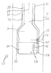
FIGURE 1 is a side elevation view, in section, of a
downhole pump assembly constructed in accordance with the
teachings of the present invention.
FIGURE 2 is a side elevation view, in section, of the
downhole pump assembly illustrated in FIGURE 1, with a
downhole hydraulic pump added to assist in the circulation of
hydraulic drive fluid.
DETAILED DESCRIPTION OF THE PREFERRED EMBODII~lENT
The preferred embodiment, a downhole pump assembly for
pumping formation water from a producing gas well, generally
identified by reference numeral 10, will now be described
with reference to FIGURES 1 and 2.
Structure and Relationship of Parts:
Referring to FIGURE 1, downhole pump assembly 10 is a
combination which includes a gas well 12, a submersible pump
14, positioned down gas well 12 at a zone producing formation
water 16, which adversely affects gas production. Submersible
pump 14 has an inlet 18 and an cutlet 20. A disposal conduit
22 connects outlet 20 of submersible pump 14 to the surface


CA 02432124 2003-06-03
4
(not shown), thereby providing a disposal path 24 for
formation water 16 pumped from outlet 20. A hydraulic drive
motor 26 is coupled to and provides a driving force to
operate submersible pump 14. Hydraulic drive motor 26 has a
drive fluid inlet 28 and a drive fluid outlet 30. A drive
fluid supply conduit 32 extends from the surface to drive
fluid inlet 28 of hydraulic drive motor 26 and a drive fluid
return conduit 34 extends from drive fluid outlet 30 back to
the surface, such that a circulation 36 of hydraulic drive
fluid originating from the surface passes down drive fluid
supply conduit 32 into hydraulic drive motor 26 through drive
fluid inlet 28 out of hydraulic drive motor 26 through drive
fluid outlet 30 and back through drive fluid return conduit
34 to the surface. Downhole pump assembly 10 is further
adapted with a fluid sensing and switching assembly 38
coupled to hydraulic drive motor 26. Assembly 38 includes a
sensor 40, adapted to sense the presence of formation water
16 and a switch 42 adapted to turn hydraulic drive motor 26
on when formation water 16 is sensed and turn hydraulic drive
motor 26 off when formation water 16 is absent. Referring to
FIGURE 2, in deep wells downhole pump assembly 10 may be
further adapted with a downhole hydraulic pump 44 coupled to
drive fluid outlet 30 of hydraulic motor 26 .for maintaining
circulation 36 of hydraulic drive fluid exiting drive fluid
outlet 30 up through drive fluid return conduit 34 back to
the surface.
Operation:
The use and operation of a downhole pump assembly for
pumping formation water from a producing gas well 10, will
now be described with reference to FIGURES 1 and
Referring to FIGURE 1, at a predetermined level, formation
water 16 within gas well 12 is detected by sensor 40 which,
in turn, switches hydraulic motor 26 on, providing drive


CA 02432124 2003-06-03
force to submersible pump 14. Formation water 16 is then
drawn through inlet 18 of submersible pump 14 and propelled
to the surface through outlet 20 along disposal path 24 of
disposal conduit 22. Circulation 36 of hydraulic drive fluid
5 is maintained through drive fluid supply conduit 32 and drive
fluid return conduit 34 from the surface. Referring to
FIGURE 2, where a gas well 12 is too deep to maintain
circulation 36 of hydraulic fluid from the surface, hydraulic
pump 44 is coupled to hydraulic motor 26. Circulation 36 of
hydraulic fluid out of outlet 30 of hydraulic motor 26 is
assisted and maintained by the motive force provided by
hydraulic pump 44 which propels hydraulic fluid to the
surface through fluid conduit 34.
In this patent document, the word. '"comprising°' is used
in its non-limiting sense to mean that items following the
word are included, but items not specifically mentioned are
not excluded. A reference to an element by the indefinite
article °'a'° does not exclude the possibility that more than
one of the element is present, unless the context clearly
requires that there be one and only one of the elements.
It will be apparent to one skilled in the art that
modifications may be made to the illustrated embodiment
without departing from the spirit and scope of the invention
as hereinafter defined in the Claims.

Representative Drawing
A single figure which represents the drawing illustrating the invention.
Administrative Status

For a clearer understanding of the status of the application/patent presented on this page, the site Disclaimer , as well as the definitions for Patent , Administrative Status , Maintenance Fee  and Payment History  should be consulted.

Administrative Status

Title Date
Forecasted Issue Date 2007-09-04
(22) Filed 2003-06-03
Examination Requested 2003-09-05
(41) Open to Public Inspection 2004-12-03
(45) Issued 2007-09-04
Deemed Expired 2020-08-31

Abandonment History

There is no abandonment history.

Payment History

Fee Type Anniversary Year Due Date Amount Paid Paid Date
Application Fee $150.00 2003-06-03
Request for Examination $200.00 2003-09-05
Maintenance Fee - Application - New Act 2 2005-06-03 $50.00 2005-03-11
Maintenance Fee - Application - New Act 3 2006-06-05 $50.00 2006-04-13
Registration of a document - section 124 $100.00 2007-03-20
Maintenance Fee - Application - New Act 4 2007-06-04 $50.00 2007-05-03
Final Fee $150.00 2007-06-26
Maintenance Fee - Patent - New Act 5 2008-06-03 $100.00 2008-04-01
Maintenance Fee - Patent - New Act 6 2009-06-03 $100.00 2009-03-17
Maintenance Fee - Patent - New Act 7 2010-06-03 $100.00 2010-06-01
Maintenance Fee - Patent - New Act 8 2011-06-03 $100.00 2011-06-01
Maintenance Fee - Patent - New Act 9 2012-06-04 $100.00 2012-05-31
Registration of a document - section 124 $100.00 2012-11-27
Maintenance Fee - Patent - New Act 10 2013-06-03 $125.00 2013-06-03
Maintenance Fee - Patent - New Act 11 2014-06-03 $125.00 2014-04-04
Maintenance Fee - Patent - New Act 12 2015-06-03 $125.00 2015-02-18
Maintenance Fee - Patent - New Act 13 2016-06-03 $125.00 2016-05-10
Maintenance Fee - Patent - New Act 14 2017-06-05 $125.00 2017-05-15
Maintenance Fee - Patent - New Act 15 2018-06-04 $225.00 2018-04-30
Maintenance Fee - Patent - New Act 16 2019-06-03 $225.00 2019-05-31
Owners on Record

Note: Records showing the ownership history in alphabetical order.

Current Owners on Record
RAISE PRODUCTION INC.
Past Owners on Record
GLOBAL ENERGY SERVICES LTD.
HOFFARTH, CLAYTON
Past Owners that do not appear in the "Owners on Record" listing will appear in other documentation within the application.
Documents

To view selected files, please enter reCAPTCHA code :


To view images, click a link in the Document Description column. To download the documents, select one or more checkboxes in the first column and then click the "Download Selected in PDF format (Zip Archive)" or the "Download Selected as Single PDF" button.

List of published and non-published patent-specific documents on the CPD .

If you have any difficulty accessing content, you can call the Client Service Centre at 1-866-997-1936 or send them an e-mail at CIPO Client Service Centre.


Document
Description 
Date
(yyyy-mm-dd) 
Number of pages   Size of Image (KB) 
Abstract 2003-06-03 1 18
Description 2003-06-03 5 241
Claims 2003-06-03 2 61
Drawings 2003-06-03 2 42
Representative Drawing 2003-10-02 1 7
Cover Page 2004-11-09 1 32
Claims 2006-07-20 2 45
Cover Page 2007-08-09 1 34
Assignment 2003-06-03 2 76
Prosecution-Amendment 2003-09-05 1 27
Correspondence 2011-04-26 1 17
Assignment 2007-04-26 7 176
Correspondence 2011-04-26 1 22
Fees 2005-03-11 1 27
Prosecution-Amendment 2005-09-22 1 42
Fees 2006-04-13 1 31
Prosecution-Amendment 2006-01-24 2 40
Prosecution-Amendment 2006-07-20 5 128
Assignment 2007-03-20 2 87
Correspondence 2007-05-22 1 14
Correspondence 2007-06-26 1 27
Fees 2007-05-03 1 27
Correspondence 2007-11-16 5 123
Correspondence 2007-12-27 1 12
Correspondence 2008-01-02 1 15
Fees 2008-04-01 2 131
Correspondence 2008-04-01 2 132
Fees 2009-03-17 1 44
Correspondence 2011-03-31 3 148
Correspondence 2012-11-15 1 18
Correspondence 2012-11-06 3 83
Assignment 2012-11-27 3 82
Correspondence 2013-01-07 1 14
Correspondence 2013-01-07 2 32
Correspondence 2013-01-02 6 166
Fees 2013-06-03 1 163
Fees 2014-04-04 1 33
Fees 2015-02-18 1 33