Note: Descriptions are shown in the official language in which they were submitted.
CA 02435947 2003-07-25
GB0200306
- 1 -
MOIJLDTNG
The present invention relates to injection moulding of
plastics material.
It is known that large, thin articles are difficult to
form-by injection moulding. The reason is that the gap
between the two parts of the mould is small and the distance
that the material has to travel is too long for the pressure
1o applied by the moulding machine to_be available at the far
end of the gap from the injection point for driving the
plastics to fill the mould. In short, the "flow path
thickness ratio" is too long.
Conventionally, thin articles are formed by vacuum or
pressure forming where a sheet of plastics material is
stretched to conform to the shape of a mould. Such
techniques are limited in their application as they cannot
produce articles of even wall thickness or articles that
2o have regions of increased or reduced wall thickness. This
is because only one surface of the article is being moulded
and the thickness at any point is determined exclusively by
the~thickness of the original sheet and the extent of its
deformation.
~P-04238009 (Togo Mach & metal Co. Ltd.) discloses a
mould for mounting between the platens of an injection
moulding machine for injection compression moulding of a
thin walled article, as set forth in the preamble of the
3o appended Claim 1. In particular, the mould comprising a
first mould part, a pressure plate movable relative to the
first mould part between first arid second end positions in
which the mould is respectively opened and closed, a core
supported by the pressure plate and movable relative to the
pressure plate in the direction of opening and closing of
the mould, a rim closure part surrounding and in sealing
engagement with the core and arranged between the first
AMENDED SHEET
CA 02435947 2003-07-25
GB020030~
mould part and the pressure plate, the first mould part, the
core and the rim closure part together defining.a mould
cavity and each being movable relative to the other two in
the direction of opening and~closing of the mould, and means
for applying a force to urge the core away from the pressure
plate towards the position of minimum mould cavity volume.
In use of the latter mould, the core is moved to
minimise the volume of the mould,cavity at the same time as
1o the pressure plate reaches its second position, i.e. when
the mould~is closed. Thereafter, the core is rapidly
retracted to increase the volume of the mould cavity to
increase injection speed. This Japanese reference provides
no teaching that assists in forming articles with a large
flow path thickness ratio.
US 4,080,147 which is more closely related to the
present invention describes a mould that is formed in three
parts. A pressure plate carries a core and the cavity is
2o defined by a double mould plate which surrounds the core. In
operation, the mould is partially closed so that the mould
cavity volume is greater than its final volume but is
nevertheless fully enclosed. A metered quantity of plastics
material is injected into the cavity. The pressure plate is
then moved to reduce the cavity to its minimum volume
thereby compressing the plastics material and forcing it to
fill the narrower section parts of the mould cavity. A
problem~with this apparatus is that the cavity contains a
significant volume of air when the plastics material is
3o metered into it. When this mass of air is compressed by the
movement of the core, its temperature rises and unless
special steps are taken to vent the mould cavity, this can
result in burn marks in the finished product.
The present invention seeks therefore to provide an
improvement which minimises the volume of air trapped in the
mould cavity while the plastics material is metered into it.
AMENDED SHEET
~
G7-0 I-2~~J CA 02435947 2003-07-25 GB0200306
- 3 -
According to one aspect the present invention, there is
provided a mould as hereinafter set forth i.n Claim 1 of the
appended claims. The invention further -provides a method of
injection compression moulding a thin walled article as set
forth in Claim 8 of the appended claims.
The invention differs from the teaching of JP-04238009
in that the pressure plate in its closed position directly
applies pressure to the core. In the present invention, the
1o plastics material already present in the mould cavity is
compressed as the mould is closed by the movement of the
pressure plate.
The invention offers the advantage over the teaching of
US-A-4.080.147 that the trapping of air in the mould is
minimised by injecting the plastics material into the~closed
mould cavity and allowing the core to retract under the
action of the injection pressure of the plastics material.
The invention may broadly be regarded as applying to
plastics material a technique similar to that used in metal
forging. A quantity of molten plastics material is placed
in the mould cavity while it is not at its minimum volume
and plastics material is then compressed by fully closing
the mould to force the plastics material into all parts of
the mould cavity.
It is known to move part of a mould in order to apply
additional compression after having injected a plastics melt
into a mould cavity in the conventional manner. This
process, which is known as injection compression moulding
(ICM) offers advantages of longer flow lengths, thinner
walls and a lower level of material stresses. This makes the
process suitable for moulding such articles as CD's and
DVD's (because of improved internal stresses) and vehicle
body and instrument panels (because of improved impact
resistance).
AMENDED SHEET
CA 02435947 2003-07-25
- 4 -
The known process used in forma.ng CD~ s differs from the
present invention in that the plastics melt is introduced
into the mould under substantial pressure anal during the
injection of the plastics melt the mould parts a.re held
' s together with sufficient force for the mould cavity to
remain, of constant volume during the injection.~By contrast
in the present invention, the injection of the plastics melt
can cause the mould parts to separate and the mould.cavity
to expand. The lighC pressure used to close the mould
so initially is intended primarily to exclude gas from the
mould cavity. This is to avoid gas pockets being trapped in
the cavity. As the melt is introduced into the mould, the
Cavity can expand as neceasaiy so that the melt flows
relatively freely to occupy part of.the volume of the
x5 cavity. Once the predetermined quantity of molten plastics
material has been introduced into the mould, the parts of
the mould are brought together under high pressure to reduce
the mould cavity to its f final 'volume and force the melt to .
flow into all parts of the cavity.
It f411ows from the above explanation that the quantity
of the plastics material needs to be predetermined because
the injection cannot simply continue until the cavity is
totally filled and the back pressure prevents Further
as injection of the plastics material into the mould. When
forming CDs, on the other hand, injection is stopped by
back pressure, at which time the plastics material may
already occupy some ninety percent of the cavity. The final
reduction in volume of the cavity is used only to force the
3o partly solidified plastics material to flaw into the last
ten percent of the mould cavity.
Tn a typical embodiment of the present invention, the
relative displacement of the mould parts under pressure is
3s zn excess of ten times the final mould thickness and may be
as great as two Hundred times the final moulding thickness.
This is to be contrasted with a corresponding movement of
...... ::...:,..,::;:::::::::::=:, ~:. ~a::,
::>:: E_ :.~::.....:..:......::;.:...:...,.::;. ...;
::: ... .. : .~~ . ..;
:::::' _::.,:."::._::.::..:..'~w.:~.!~ r~.
,. AM ENDED S H E I .':'<:"'::':~~-.'-.
CA 02435947 2003-07-25
- 5 -
some twice the final wall thic3;.ness, that is typically used
in injection compression moulding.
A further important difference between the invention
and conventional injection. compression moulding resides in.
the speed of closing the mould and the rate of pressure
increase within the mould~cavity during the closing process.
In the present invention, the mould is closed and maximum '
pressure is reached within the cavity within a period of
so less than 0.5 seconds and preferably less than 0.3~ seconds.
By contrast, in inj ection compression mouldixa,g~, after the
plastics material has been injected under pressure to f ill a
major paxt of the mould and cavity, the pressure is romped
up progressively to flow the plastics material to fill the
is remainder of the mould.
The.most important difference however between the
invention and earlier proposals resides in the application
of a ~.ight pressure to close the mould while injection is
zo taking.place and a higher pressure to compress the injected
plastics material after completion of the injection phase.
The relevance of this difference will be described by
reference to the moulding of drinkix~.g cups, this being an
2s eaamp 1e of an article to which the invention particularly
lends itself. When forming.a drinking cup, the plastics
' material is injected into the base of the cup and the
application of high pressure to close the mould after
completion of the ~.nj ecti.on step forces the plastics
3o material to flow upwards from the base to form the side
walls of the cup and any lip surrounding the mouth.
In such an application, it is essential to avoid gas
being trapped in the bottom corners of the mould.cavity at
35 the junction between the base and the side walls.
Compression of such gas raises its temperature and cause9
unacceptable burn marlcs in the finished products.
:: A AA F N f1 F f1 ~ l-L F F ~ ::::::::::::::::~:.::;>::.;..~.:.,~..;:.
~E$
CA 02435947 2003-07-25
- 6 -
. If the plastics material were injected into a fully
open cavity, it would form a small sphere which would be
flattened when the mould parts are brought together,at high
speed and wou7.d trap gas in the corners of the,moulds. Tn
s the present invention, this is avoided because the injected
plastics material does not form a sphere in the first place.
vnstead, the mould is~closed or at least nearly closed under
light pressure and the injected plastics material flows as a
radially expanding disc which forces the mould parts apart
to if necessary until it totally fills the base of the cup.
When the pressure is increased to force the injected
plastics material up_the side_walls of the cup, there will
be no gas trapped in the corneas to cause burn marks.
i~ It is important that the cavity volume should be fu~.ly
~antained at all stages after the commencement of injection
.of the plastics melt. Although thewolume of the cavity
must~be variable, the melt must not be allowed to escape
from the cavity.
ao '
The mould is preferably provided with means for
aligning the rim closure part relative to the first-mould
part in order to achieve accurate alignment of the movable
j core in relation to the remainder of the mould. cavity.
2~
A spring and/or a damper is preferably provided to ~.
resist.retraction of the core away from the first mould part ,
into the pressure plate.
30 One can envisage an implementation of the invention
w ing a moulding machine with a hydraulic lock ti.e. one
that uses only hydraulic actuators to apply all the
necessary pressure to the mould partsy. Using such an
approach, it is more difficult to achieve the necessary
3s speed of closure of the mould cavity as well, as the rapid
rise in pressure that is needed as the mould parts approach
the.ix closed position. This may therefore require the use
A(VIENDED SHEET
~:;.....,...,.: E
CA 02435947 2003-07-25
7
of purpose built machines. In this respect, it should be
noted that the plastics material is Gaoled and.sets as it
makes contact with the mould surfaces and it vital far this
reason that the flowing of the plastics material by the
s closing of the mould parts should be completed as quickly as
possible. An injection. moulding machine with a toggle
closure mechanism has however been found to be well adapted
to provide the substantial force require to effect the final
closure.
io
Since the pressure in the plastics material on final
closure is substantial, the injection gate through which the
plastics material is injected into the mould is preferably
closed by a valve prior to final mould closure. This is to
Z~ avoid expulsion of material from the tool during final
closure,
Preferably, the closure of the mould under high
pressure involves reduction of the mauld.part gap over a
2o substantial portion of the surface area of the finish formed
article, whereby movement of the plastics material through a
thin mould part, which might otherwise be regarded as too
thin, occurs only during the last part-o.f the final closure.
zn order to introduce an accurately predetermined
quantity of molten plastics material, it is preferred to
provide a hot-runner system that comprises a manifold
incorporating a dosing cylinder for each of~the cava,ties,
each dosing cylinder being connected to a common pressurised
ao supply of molten plastics material by way of a respective
valve and being connected to the associated,cavity by way of
a gate valve.
Each dosing cylinder comprises a variable volume
3s Chamber bounded by a piston which acts to store the required
:_.:_... ::.:...::__:.::::::::::::_.::.:::::::....>,:
AnnF~~nFn :.:-.-...........:..............
:::: .~._;.':.._.:T...y.'
:.. ~N~~T ::::::::::..::::::::::::....~..,
~~. :v ~"'~~. y:::::.:::
CA 02435947 2003-07-25
WO 02/058909 PCT/GB02/00306
_ g _
dose of plastics material for its associated cavity. When
the plastics material is injected from the pressure source
into the dosing cylinders, it will first flow to the dosing
cylinder offering the least resistance but when this pot is
full the plastics material will meet resistance and will be
diverted to another of the dosing cylinders until all the
dosing cylinders are full. An adjustable stop may be
provided for each of the pistons of the dosing cylinders to
allow fine adjustment of the quantity of plastics material
to delivered to each cavity. When the gate valves are opened
and the pistons of the dosing cylinders are moved in a
direction to reduce the volume of the working chambers, the
stored plastics material is forced past the gate valve into
the cavity and is prevented from moving in the opposite
direction.
The invention will now be described further, by way of
example, with reference to the accompanying drawings, in
which .
2o Figure 1 is a schematic representation of a
conventional moulding machine,
Figure 2 is a section through a mould when fully open,
Figure 3 is a section through the mould of Figure 1
immediately prior to injection of the plastics melt,
Figure 4 is a section through the mould of Figure 1
during the injection of the plastics melt,
Figure 5 is a section through the mould of the
preceding Figures with the mould cavity fully closed,
Figure 6 is a view similar to that of Figure 3 showing
3o an alternative embodiment of the mould that uses an
accumulator in place of a coil spring, and
Figure 7 is a schematic section through part of a hot
runner manifold showing one of the dosing cylinders used to
ensure that all the cavities receive an equal quantity of
plastics melt when using a multiple cavity mould connected
to a common feed screw.
CA 02435947 2003-07-25
WO 02/058909 PCT/GB02/00306
- 9 -
The moulding machine shown in Figure 1 is generally
conventional and will therefore only be described in the
detail necessary to understand the Injection Impact
Compression (IIC) method of the invention. The moulding
s machine 10 comprises two stationary bulkheads 12 and 14
connected to one another by four tie bars 16. A convention
mould 18 is shown which is formed of two parts, namely a
stationary part 18a mounted on the bulkhead 12 and a movable
parts 18b mounted on a platen 20 that can slide along the
Zo tie bars 16. The platen 20 is moved towards and away from
the bulkhead 12 by a hydraulic ram 22 that is mounted on the
bulkhead 14 and is connected to the platen 20 by a toggle
mechanism which. comprises levers 24a pivoted on the bulkhead
14, levers 24b pivoted on the platen 20 and levers 24c
15 pivoted on the ram 22, the other ends of all three levers
24a, 24b and 24c being pivoted to another. The levers of the
toggle mechanism are shown in their position when the mould
cavity is open and to close the mould cavity, the ram moves
to the right as viewed so that the levers 24c move into a
2o more vertical position and acts on the levers 24a and 24b to
move them into alignment with one another, thus moving the
platen 20 and the mould part 18 towards the closed position.
A heated screw feed mechanism 30 heats and compresses
25 granules drawn from a hopper by rotation of the screw to
form a plastics melt and the screw can also be moved axially
to inject the melt into the mould cavity through a set of
runners.
3o As earlier indicated, the machine of Figure 1 is
already known for injection moulding. Conventionally, the
mould cavity is closed and the injection screw is advanced
to provide all the necessary pressure to inject sufficient
melt to fill the cavity. After the plastics material has set
35 in the mould, it is opened, the formed article is ejected
and a new cycle is commenced.
CA 02435947 2003-07-25
2 ~ -0 i -2003 GB0200306
- 10 -
This known method of operation has its limitation and
cannot be used to form articles that have a very thin wall
section. This is because as the plastics material is
injected, it cools very rapidly on contact with the mould
surface and creates a large back pressure that prevents the
plastics material from filling the entire cavity.
In the present invention, the injection screw is not
relied upon to produce enough pressure to fill a closed
1o mould cavity. Instead, the screw is used to inject a dose of
the melt into the mould while the mould cavity is not closed
under pressure and subsequently the mould parts are brought
together rapidly using the ram 22 to "forge" the plastics
material and force it rapidly to fill every part of the
mould cavity.
An operating cycle will now be considered into greater
detail with reference to Figures 2 to 5.
2o In place of a conventional two part mould 18a, 18b as
described by reference to Figure 1, the preferred embodiment
of the invention uses a mould assembly 50 comprising four
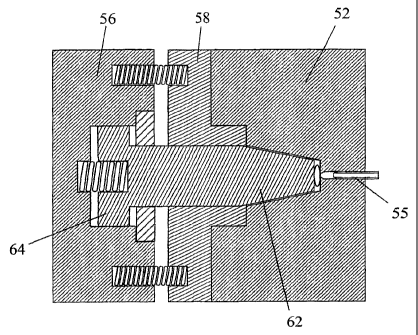
components that can move relative to one another. The first
of the four components is a stationary cavity assembly 52
that defines the cavity 54 and is formed with a feed gate 55
through which the plastics melt is injected into the cavity.
The cavity assembly is fixed to the bulkhead 12. The feed
gate 55 and the control pin that opens and closes the gate
will be described in more detail below in the context of the
3o manner of introducing an accurate dose of the plastics~melt
into the mould cavity 54.
The other three components, which together constitute
the core assembly, are mounted on the moving platen 20 of
the moulding machine. A first of the three components,
herein termed the pressure plate, is designated and is fixed
to the moving platen 20. The second of the components is
AMENDED SHEET
CA 02435947 2003-07-25
WO 02/058909 PCT/GB02/00306
- 11 -
termed a rim closure plate and is designated 58 in the
drawings. The rim closure plate is biased away from the
pressure plate 56 by relatively strong springs 60 and is
accurately aligned and guided so that a projecting boss 59
s engages in a recess 53 in the mould part 52 of the cavity
assembly. The last of the components of the mould is a core
62 which partly defines the mould cavity and has a
cylindrical portion that slides freely through and is
accurately guided within a through bore formed in the rim
so closure plate 58.
The core 62 at its end remote from the mould cavity is
formed with an enlarged head 64 that is received in the
manner of a piston in a chamber 66 formed in the pressure
15 plate 56. A weak spring located in the chamber 66 urges the
core away from the pressure plate towards annular stop plate
70 that is fixed to the pressure plate 56 and surrounds the
cylindrical region of the core 62. The enlarged head 64
trapped between the pressure plate 56 and the stop plate 70
2o forms a lost motion coupling arranged in the line of action
between the core 62 and the machine platen 20.
In the embodiment of Figures 2 to 4, that the head 64
does not form a seal with the chamber 66 and the stop plate
25 70 does not seal against the core 62. Instead, small
clearances allow air to escape while damping the movement of
the core 62.
Figure 2 shows the mould in the position at the end of
30 one cycle and the commencement of the next. The cavity is
open and the formed article, in this case a drinking cup, is
ejected from the cavity in a conventional manner (not
shown). The toggle mechanism now moves the core assembly
towards the cavity assembly until the position shown in
35 Figure 3 is reached or at least nearly reached. In this
position the boss 59 of the rim closure plate 58 is fully
engaged in the recess 53 of the cavity assembly 52 and the
CA 02435947 2003-07-25
27-0'! -2003 GB0200306
- 12 -
strong springs 60 ensure the cavity is .fully contained
against the egress of plastics melt from the mould cavity
even though the core can still move to allow the cavity
volume to vary.
In the next step, plastics melts is introduced at
relatively low pressure into the mould cavity through the
feed gate 55. At this point, the pressure of injection of
the plastics melt can push the core 62 back against the
to action of the weak spring 68. The injection can be timed to
occur just before or just after the core reaches the bottom
of the cavity 54 so that as the melt enters the cavity it
spreads into~the corners of the cavity without trapping any
gas between the melt and the corners of the mould. The
25 injection pressure is not however sufficient to force the
plastics melt into the narrow parts of the mould cavity, in
this case the conical wall of the drinking cup:
- Lastly, the pressure plate 56 is moved by the platen 20
2o to apply a force directly to the core 62 after full
compression of the weak spring 68. The pressure resulting
from the movement of the core under the force of the
hydraulic ram 22 as magnified by the mechanical advantage of
the toggle levers is sufficiently great to forge the melt
25 and thereby fill all parts of the mould.
The term "forge" is used in order to stress the speed
of closing the mould and the rate of pressure increase
within the mould cavity during the closing process.
3o Typically, the mould is closed and maximum pressure is
reached within the cavity within a period of less than 0.5
seconds and preferably less than 0.3 seconds. By contrast,
in prior art injection compression moulding, after the
plastics material has been injected under pressure to fill a
35 major part of the mould and cavity, the pressure is only
ramped up progressively to flow the plastics material to
fill the remainder of the mould.
AMENDED SHEET
CA 02435947 2003-07-25
27-0~-2003 GB0200306
- I3 -
- The embodiment of Figure 6 differs from the previously
described embodiment only in that a gas spring or
accumulator 80 is used in place of the coil spring 68. In
' this case, as represented by O-rings in the drawing, the
head 64' of the core 62 does seal against the wall of the
chamber 66 and the stop plate 70' seals against core 62.
The two working chambers on opposite sides of the head 64'
are connected through passages 82 formed in the pressure
plate 56 and through external lines 86 and various valves 88
1o to the accumulator 80 and to atmosphere. The function is
entirely analogous to that of a coil spring 68 in that the
core 62 can move against weak resistance when the melt is
injected into the cavity but the full force of the pressure
plate 56 and the platen 20 acts on the core 62 when the core
assembly reaches the end of its travel.
G~Then plastics material is normally injected into a
mould having multiple cavities, the melt follows the path of
least resistance. Thus the melt will first flow to the
2o cavity nearest the feed screw and as that cavity f ills its
resistance increases so that the melt flows to the other
cavities, this being repeated until all the cavities are
full. Such an approach cannot be used in the present
invention because the melt always meets little resistance
even after a cavity has received its full dose of plastics.
material. Relying on back pressure would result in all the
plastics material flowing to the first cavity and none to
the others.
3o To avoid this problem, the preferred embodiment of the
invention.uses a special hot runner system, shown in Figure
7, to distribute the plastics material to the individual
cavities. As with all hot runner systems, the manifold 100
has a single inlet 90 which is connected to the screw and
several outlets each constituted by the feed gate 55 of a
respective cavity. Control pins 94 that open and close the
AMENDED SHEET
CA 02435947 2003-07-25
WO 02/058909 PCT/GB02/00306
- 14 -
feed gates are all actuated by a common slider 96 that moves
in and out of the plane of the drawing.
The control pins also act as spool valves. In
s particular, in one of their end positions, the control pins
94 allow plastics material to flow from the inlet 90 to the
working chamber 102 of a dosing cylinder 98 associated with
a respective mould cavity. During this time, the mould
cavity is closed. In their other end positions, the control
to pins open the feed gate, isolate the dosing cylinder 98 from
the inlet 90 and connect it instead to the feed gate. When
the piston is now moved, it injects the quantity of the
plastics melt contained in the working chamber 102 into its
associated mould cavity. By adjusting a stop that limits
z5 the stroke of each piston, the quantity of plastics material
injected into each cavity can be accurately and separately
metered.
The pistons of the dosing cylinders 98 can be actuated
2o by an independent mechanical, electrical or hydraulic
mechanism but it is alternatively possible to arrange for
the pistons to be mounted parallel to the axis of relative
movement of the components of the mould so that the force
for injecting the plastics melt into the cavities may be
2s derived from the movement of platen 20. In particular, the
pistons may be actuated by the rim closure plate 58.