Note: Descriptions are shown in the official language in which they were submitted.
CA 02438192 2007-04-18
1
Title of the Invention
SYSTEM FOR RECONSTITUTING PASTES
AND METHODS OF USING SAME
Background of the Invention
The ability to preserve biomedical substances has a great impact on the
usefulness
and applicability of such substances. This is especially true for important
liquid or semi-
solid substances whose vital components are prone to degradation and/ or
spoiling when
left in liquid form for extended periods of time. One method routinely
utilized for
preserving liquid or semi-solid substances involves the removal of the aqueous
component
of such substances (e.g. freeze-drying) to produce a dry powder. While
converting liquid
substances into powder form may address the problems of degradation and
spoiling,
problems still arise as to how to reconstitute such powders back into usable
liquid form in
a convenient and practical fashion.
An example of an increasingly important biomedical substance is osteogenic
Bone
Paste (WO 98/40113). Osteogenic Bone Paste has provided surgeons with a
revolutionary
means for repairing serious bone defects, as well as other bone-related
injuries and
problems. While current methods of utilizing bone paste have shown promise,
there is a
constant need for devising new, cost-effective techniques of storing and
preserving bone
paste and other biomedical substances, which, in turn, will increase their
usefulness and
adaptability to medical applications.
CA 02438192 2003-08-12
WO 02/067814 PCT/US02/05903
2
Summary of the Invention
The subject invention concerns a system that allows for a more expeditious and
facile use and preparation of pastes. Specifically exemplified is a novel
system for
reconstituting bone paste, and/or other biomedical pastes or powders, that
results in
decreasing the time involved in processing such pastes, as well as diminishing
the costs
and inefficiencies associated with their storage. One aspect of the subject
invention
pertains to a system that comprises a first syringe containing reconstitution
liquid and a
second syringe containing paste components, wherein said first and second
syringes are
communicatingly interconnectable.
Another aspect of the subject invention pertains to a method of reconstituting
a
paste that comprises obtaining a first syringe that contains reconstitution
liquid; obtaining a
second syringe that contains paste components; and contacting (e.g. mixing)
the contents
of the first syringe with the contents of the second syringe.
A further aspect of the subject invention pertains to an article of
manufacture
comprising a syringe containing paste components under a vacuum.
Yet another aspect of the subject invention pertains to a kit comprising a
first
syringe containing reconstitution liquid, a second syringe containing paste
components,
and packaging materials.
Further still, another aspect of the subject invention pertains to a storing
method for
bone pastes that provides long-shelf life and simple implementation of the
stored bone
paste.
Further still, another aspect to the subject invention pertains to a mixing
syringe
that comprises a barrel having a first and second ends and a midsection that
comprises a
flexible portion. When contents are put in the mixing syringe, they can be
easily mixed by
squeezing the flexible portion by hand or by appropriate mechanical devices
known in the
art.
The subject invention provides an easy means for preparing pastes for
utilization in
medical and/or dental procedures. In addition, the subject invention cuts down
on the costs
of preserving bone and/or other biomedical pastes, and extends their shelf
life. With
CA 02438192 2010-01-18
3
respect to graft pastes, current methods require that they are stored at
extremely cold
temperatures (-80 C). Such freezing presents a number of problems.
Refrigeration at
these temperatures is very costly, and the handling of the pastes at this
temperature can be
very time consuming. Also, extremely careful attention is required to ensure
that the
integrity of the paste is maintained. In contrast, the subject invention
allows the graft
paste to be processed down to its critical components, for example, by freeze-
drying, and
provides a simple means to reconstitute the paste components back into a
workable paste,
immediately before surgery. Processing the graft paste into its critical
components allows
for the storage of the paste at ambient (room) temperature for extended
periods of time.
The subject invention also pertains to freeze-dried compositions that possess
osteogenic, chondrogenic or chondroprotective, or other beneficial properties.
The subject
dried paste compositions are capable of being stored at room temperature and
retaining
their osteogenic, chondrogenic, or chondroprotective properties upon
reconstitution.
According to one aspect of the present invention there is provided a dried
bone
paste composition comprising freeze-dried demineralized bone matrix particles
and a
carrier, wherein the carrier is gelatin, wherein the gelatin is in the form of
granules having a
size between 125 microns and 710 microns
According to a further aspect of the present invention there is provided a
reconstituted bone paste composition comprising an admixture of a dried bone
paste
composition comprising freeze-dried demineralized bone matrix particles and a
carrier,
wherein the carrier is gelatin, wherein the gelatin is in the form of granules
having a size
between 125 microns and 710 microns; and reconstitution fluid, wherein the
reconstitution
fluid is selected from the group consisting of water, water-based salines,
blood or fractions
thereof, protein solutions, gelatin solutions, growth factor solutions,
antibiotic solutions,
analgesic solutions, platelet rich plasma, and combinations thereof.
According to another aspect of the present invention there is provided a
reconstituted bone paste composition comprising an admixture of a dried bone
paste
composition comprising freeze-dried demineralized bone matrix particles and
gelatin
wherein the gelatin is in the form of granules having a size between 125
microns and 710
microns; and reconstitution fluid, wherein the reconstitution fluid comprises
water.
According to a still further aspect of the present invention there is provided
a dried
bone paste composition comprising freeze-dried demineralized bone matrix
particles and a
carrier, wherein the carrier is gelatin wherein the gelatin is in the form of
granules having a
CA 02438192 2010-01-18
3a
size between 125 microns and 710 microns, wherein the dried bone paste
composition is
stored at ambient temperature for more than 24 hours, and wherein the dried
bone paste
composition is osteogenic, chondrogenic, or chondroprotective or a combination
thereof upon
reconstitution.
The ability to store freeze-dried bone pastes at room temperature and then
reconstitute the paste prior to surgery is one of the primary advantages of
the subject
invention. These and other advantageous aspects of the subject invention are
described in
further detail below.
Description of the Drawings
Figure 1 shows a side view of a disassembled apparatus for reconstituting
pastes
according to the principles of the subject invention, including a first
syringe having a male
connector end (Figure 1A) and a second syringe having a female connector end
(Figure
I B).
Figure 2 shows a longitudinal cross-section of the assembled apparatus as
shown
in Figure 1.
Figure 3 shows an embodiment of the invention illustrating an assembled
syringe
comprising a septum cap engaged thereon for accepting a needle.
Figure 4 shows an embodiment of the invention illustrating the assembled
syringe
of Figure 3 accepting a needle for the transfer of reconstitution fluid.
CA 02438192 2003-08-12
WO 02/067814 PCT/US02/05903
4
Figure 5 shows a side view of an embodiment of the invention illustrating a
syringe with a depression interlock disposed thereon for securing the syringe.
Figure 6 shows a side view of an embodiment of the invention illustrating a
syringe with a guard rack designed for aiding the loading of paste components
into the
syringe.
Figure 7 shows a side view of an embodiment of the invention tailored for
reconstituting larger quantities of paste components that comprises a three-
way valve
coupler.
Figure 8 shows a side view of an embodiment of the invention comprising
1o interconnectable syringes having larger bores and fasteners.
Figure 9 shows a perspective view of the embodiment shown in Figure 8.
Figure 10 shows a side view 10A and a perspective view lOB of an embodiment of
the invention pertaining to a plunger comprising an aperture and channel to
facilitate
expulsion of air from the contents of a syringe.
Figure 11 shows a side view of a mixing syringe, disassembled (Figure 1 1A)
and
assembled (Figure 1 1B), having a flexible midsection to facilitate mixing of
its contents.
Figure 12 shows a side view of another version of the mixing syringe,
diassembled
(Figure 12A) and assembled (Figure 12B), wherein the plunger of the syringe
has a larger
end for stabilizing a portion of the flexible midsection.
Figure 13 shows a longitudinal cross-section of a first configuration (Figure
13A)
of the first end of the barrel shown in Figures 11 and 12; a second
configuration (Figure
13B) representing a transverse cross-section along line AA; and a third
configuration
(Figure 13C) which is shorter in length.
Figure 14 shows the configuration as shown in Figure 13C rigidly attached to
the
first end of the barrel of the mixing syringe shown in Figures 11 and 12.
CA 02438192 2010-01-18
Detailed Disclosure of the Invention
Definitions
5 The term "communicatingly interconnectable" as used herein refers to the
ability of
two or more syringes to be connected in such as way as to allow the contents
of a given
syringe to be transferred to another syringe.
The term "paste" as used herein refers to a malleable composition useful in
medical procedures. Pastes for use with the principles of the invention
include, but are
not limited to allograft pastes (e. g., osteogenic pastes or chondrogenic
pastes), carrier
associated Growth Factors, carrier associated mineralized particles,
morsellized skin or
other tissue, Fibrin powder, Fibrin/plasminogen glue, biomedical plastics,
Demineralized
Bone Matrix (DBM)/glycerol, cortico cancellous chips (CCC), DBM/pleuronic
F127T"',
and DBM/CCC/F 127, human tissue/polyesters or polyhydroxy compounds, or
polyvinyl
compounds or polyamino compounds or polycarbonate compounds or any other
suitable
viscous carrier; or alpha-BSMO or polyethylene oxide, polyvinvyypyrrolidone,
polyvinyl
alcohol, collagen and dextran. Preferably, pastes used in accordance with the
principles
of the subject invention are graft pastes having osteogenic or chondrogenic
properties.
Furthermore, the paste components can include other materials such as, but not
limited to,
antibiotics, sucrose, dextrose or other biologically compatible anti-caking
agents, and
optionally, barium, iodine, or other high atomic weight elements for purposes
of
radioopacity.
In a most preferred embodiment, the paste for use as taught herein contains a
carrier, an osteoconductive component, and an osteoinductive component.
Carriers can
include, but are not limited to, gelatin, collagen, glycerol, hyaluronic acid,
chondroitin
sulfate, polyethylene oxide, polyvinvlypyrrolidone, polyvinyl alcohol, dextran
and/or
mixtures thereof. Osteoconductive materials suitable for use with the subject
invention
include, but are not limited to, hydroxapatite (HA), tricalcium phosphate
(TCP), CCC,
bioactive glass, bioactive ceramics, and/or mixtures thereof. Osteoinductive
materials
suitable for use with the subject invention include, but are not limited to,
DBM, and'
CA 02438192 2003-08-12
WO 02/067814 PCT/US02/05903
6
growth factors such as bone morphogenic protein (BMP), TGF-beta, PDGF, and/or
mixtures thereof.
The term "paste components" as used herein refers to those components of a
paste
that are produced by removing liquid from a paste, and are capable of
reconstitution into a
workable paste upon contact with a reconstitution liquid. One skilled in the
art will readily
appreciate processing methods suitable in accord with the principles of the
subject
invention. Preferably, paste components are those components produced by
removing
water from a paste of interest, such as, but not limited to, by freeze-drying
of a paste.
The term "reconstitution liquid" as used herein refers to a liquid capable of
reconstituting paste components into a workable paste upon mixing with the
paste
components. Reconstitution liquids useful in accordance with the principles of
the subject
invention include, but are not limited to, water and water-based salines, or
any other non-
toxic fluid such as blood, Growth Factor solutions, antibiotic solutions,
protein solutions,
gelatin solutions, analgesic solutions, synovial fluid and platelet rich
plasma. In a
preferred embodiment, the reconstitution fluid is blood, or fractions thereof
(e.g., serum or
plasma). More preferably, paste components are reconstituted with a patient's
blood to
form a paste that is implanted back into the patient.
The term "syringe" as used herein refers to an apparatus that comprises a
barrel and
plunger, which is capable of containing a substance, and ejecting that
substance at a
desired site. In a preferred embodiment, two or more syringes are connectable
with each
other, and are capable of sending and receiving their contents to and from
each other. The
mode of actuating the transfer of a syringe's contents can be by hand, but can
include other
mechanical means, for example, by a motor. In an even more preferred
embodiment, the
syringe is capable of holding its contents under a vacuum, preferably, up to 5
years or
more. Further, as discussed above, the syringes are preferably communicatingly
interconnectable. One means of connection includes, but is not limited to, the
presence of
a male Luer-type connector on a first syringe and a female Luer-type connector
on a
second syringe. The presence of this reciprocal male and female connection not
only
provides for a simple and efficient interconnection, but decreases undesirable
"dead" space
between the two syringes. Other means of connection will be readily
appreciated by those
CA 02438192 2003-08-12
WO 02/067814 PCT/US02/05903
7
skilled in the art, such as, for example, a stop-cock for receiving two male
connectors or a
two-sided female adapter for receiving two male connectors.
Turning now to the drawings, a reconstitution system is shown generally in
Figure
1-3. The system comprises a first syringe 10 and a second syringe 12
communicatingly
interconnectable with each other. Syringes 10 and 12 comprise substantially
cylindrical
body portions 11, suitable for receiving a plunger rod 20. Plunger rod 20 has
disposed on
one end a crown 21, made of a material for forming a seal between its surface
and the
surface of the inner walls of the syringe body 11. Materials contemplated for
the crown 21
include, but are not limited to, rubber and plastic. Second syringe 12
preferably has a
female end 16 for receiving a male end 14 of first syringe 10. As shown in
Figure 2, the
first syringe 10 comprises paste components 26 and the second syringe 12
comprises
reconstitution fluid 28. The reciprocating male and female ends provide for a
tightly
sealed connection that minimizes "dead" space between the two syringes,
thereby
alleviating unwanted air bubbles. Alternatively, albeit less preferred, a
first syringe and a
second syringe may be connected by an adapter having two male ends, two female
ends or
a male end and female end, depending on the ends of the first and second
syringes.
Further, the first syringe and second syringe may be connected through
friction by
snapping into each other, or snapping into an adapter.
In yet another embodiment, the introduction of air is minimized in the system
through the use of a stopcock valve. In this embodiment, a first syringe and a
second
syringe are evacuated and then communicatingly interconnected via a stopcock
valve.
Upon rotation of the stopcock valve, the contents of one syringe are allowed
to flow into
the other syringe. In light of the teachings herein, those skilled in the art
will appreciate
the types of valves suitable for this purpose. The important aspect of the
valve is the
ability to interconnect to at least two syringes.
Operation of the system to reconstitute a paste can comprise applying pressure
to a
first plunger rod 20 of syringe 12 which thereby pushes the reconstitution
fluid 28 into
syringe 10. Upon transfer of the reconstitution fluid 28, it is brought into
contact with the
paste components 26. Preferably, the plunger rod 20 in syringe 10 is gradually
pulled in
coordination with the pushing of rod 20 in syringe 12 to create negative
pressure and more
CA 02438192 2010-01-18
8
space in syringe 10 to aid in and accommodate the transfer of the
reconstitution fluid 28.
In a preferred embodiment, the paste components are inserted into syringe 10,
and
syringe 10 is evacuated such that the paste components are held under a
vacuum. Once an
adequate amount of reconstitution fluid is transferred from syringe 12 to
syringe 10, the
contents of syringe 10 can be transferred back to syringe 12 whereby the paste
components and reconstitution fluid are mixed resulting in a useable paste.
Preferably,
the contents of each syringe are transferred several times until the desired
consistency of
the paste is achieved.
As shown in Figure 3, another embodiment of the invention is directed to a
system
for reconstituting pastes comprising a first syringe 10 containing paste
components 26 held
under a vacuum and a removable cap 30. The removable cap 30 comprises a rigid
portion
33 that is engaged to the end of the syringe 10 and a septum portion 34. The
rigid portion
preferably includes an end configured to be removably engageable to the end of
a syringe.
More preferably, the end 33 is a male or female connecting end. The septum
portion is
preferably made of a material that is capable of accepting an injection means
(for example,
a needle; see U. S. Patent No. 5,951,160 for other examples of injection
means) while still
maintaining the seal of the syringe 10, such as, but not limited to, rubber,
silicone, plastic
and other elastic materials.
A further embodiment shown in Figure 4 pertains to a system for reconstituting
pastes. Operation of this embodiment involves drawing reconstitution fluid
into a syringe
50 equipped with a needle 52 on its end. The needle 52 is inserted into
syringe 10 through
the septum portion 34 of the cap 30 and the reconstitution fluid 28 is
transferred into the
syringe 10. Preferably, the reconstitution fluid 28 is transferred while the
transfer of any air
is avoided. Once the reconstitution fluid 28 is transferred into syringe 10,
the cap 30 is
removed, at which time a second syringe is interconnected with syringe 10. The
paste
components and reconstitution fluid present in syringe 10 are mixed by
transfer back and
forth from syringe 10 to the second syringe until a paste of a desired
consistency is formed.
In a preferred embodiment, the paste components comprise a gelatin material
which is
melted by heating prior to mixing. Preferably, heating may occur in a water
bath for 3 to
CA 02438192 2010-01-18
9
minutes. After the paste is formed, the syringe 10 and the second syringe are
dissociated,
and the paste is ejected as needed.
In another embodiment, as shown in Figure 5, the subject invention is directed
to
an article of manufacture that comprises a syringe 10 that contains paste
components 26
5 being held under a vacuum. To aid in preventing the inadvertent release of
the vacuum, a
depression interlock 62 is provided that protects the plunger rod from
sliding.
Alternatively, the syringe comprises a cap 30 engaged at one end. The cap 30
preferably
comprises a rigid portion 33 and a septum portion 34. Those skilled in the art
will readily
appreciate, in light of the teachings herein, other devices suitable for
preventing the
inadvertent depression of the plunger rod.
A further embodiment of the subject invention is directed to kit comprising a
first
syringe containing paste components, a second syringe, and a container for
housing the
syringes. Preferably, the second syringe contains reconstitution fluid. In a
more preferred
embodiment, the kit comprises a cap that has a rigid portion for engaging a
syringe and a
septum for accepting a needle. In an even more preferred embodiment, the kit
comprises
a needle having an end for engaging a syringe.
Figure 6 shows an embodiment of the invention that is directed to a process
for
packing paste components into a syringe. Paste or paste components 26 are
placed within
a syringe 10 having disposed thereon a guard rack having a bottom 61, two or
more sides
63, and two or more top portions 65 extending perpendicularly from the ends of
the sides
63 that are opposite the bottom 61. The top portions 65 preferably extend
toward each
other such that a space is formed between the two extended top portions 65
that is of a
suitable size to accommodate a plunger rod 20 and support the bottom end 17 of
the
syringe 10. To produce an evacuated syringe, a cap 30 is placed loosely onto
the top end
of the syringe 10, and the syringe 10 disposed on the guard rack is placed in
a
lyophilizer. Upon lyophilization of the contents in the syringe 10, the
syringe 10 and guard
rack is raised such that the cap 30 comes into contact with a roof surface of
the lyophilizer.
The cap 30 is contacted with a force sufficient to firmly engage the cap 30
onto the syringe 10, to thereby form and maintain a vacuum. Alternatively, a
valve is
removably engaged to said syringe. The configuration of the guard rack and the
syringe
CA 02438192 2010-01-18
10 prevents the depression of the plunger rod during loading of the syringe
10. Those
skilled in the art will readily appreciate, in view of the teachings herein,
other devices
suitable for preventing depression of the plunger rod such as the depression
interlock
5 discussed above.
Figure 7 shows a further embodiment 700 of the invention that is especially
tailored
to reconstitute larger quantities of paste components. Embodiment 700
comprises a three-
way valve coupler 710 that has three Luer-lok adapter ends: a first female end
712, a
second female end 714, and a male end 716 that are interconnectable with
corresponding
10 Luer-lok ends on a first syringe 720 having a male end 725, a second
syringe 730 having a
male end 735, and a third syringe 740 having a female end 745, respectively.
Those
skilled in the art will recognize that the Luer-lok adapter ends of the three-
way valve
coupler 710 are readily interchangeable with either male or female Luer-lok
ends. The
three-way valve coupler 710 is equipped with a rotatable valve 750 (preferably
a
conventional Qosina valve) that is capable of directing communication between
two of
three adapter ends. In a preferred embodiment, first syringe720 and third
syringe 740 are 5
cc syringes and second syringe 730 is a 20 cc syringe.
The preferred operation of embodiment 700 is as follows: Syringes 720, 730,
and 740
are connected to the three-way valve coupler 710. Syringe 720 contains
reconstitution fluid,
syringe 740 contain paste components, and syringe 730 is empty. Rotatable
valve 750 is
turned to 9 o'clock (as shown) to close flow to syringe 720 and opening flow
between
syringes 730 and 740. The plunger of syringe 730 is pulled to draw air out of
paste
components contained in syringe 740. After removing air, syringe 730 can be
removed and
rotatable valve 750 is turned to open flow between syringes 720 and 740. The
plunger of
syringe 720 is pushed and the plunger of syringe 740 is pulled to draw
reconstitution fluid
into syringe 740. The contents of syringe 740 is then transferred back to
syringe 720 and back
to syringe 740, and repeated if necessary, to mix the reconstitution fluid
with the paste
components, until desired mixture is achieved.
CA 02438192 2010-01-18
11
Alternatively, or preferably, when reconstituting larger quantities of paste
components,
syringes equipped with larger bores over standard Luer-lok ends are used to
accommodate
and facilitate flow of the materials to and from the syringes. Figures 8 and 9
represent a
side view and perspective view, respectively, of syringes equipped with larger
bores:
female 810 and male 820. Those skilled in the art will appreciate that the
ends of the
syringes and three-way valve coupler shown in Figure 7 and described above for
embodiment 700, as well as the other connecting ends of devices described
herein, can be
substituted with ends having extra-large bores. Preferably, the extra-large
bores range from
about 0.4 inches to about 0.6 inches in diameter for 5-10cc syringes.
Typically, it is desirous to remove air from the paste components before,
during or after
reconstitution is conducted. In a specific embodiment, the removal of air is
facilitated by
providing an aperture in the plunger of the syringes used in accord with the
teachings
herein. For example, figure 10 shows a plunger 1000 having an aperture 1010 at
its end
1020 in contact with paste components, wherein the aperture communicates with
the other
end of the plunger 1030 through a channel 1040 defined within the plunger
1000.
Preferably, to prevent escape of paste components or reconstitution fluid, the
aperture is
covered with an air-permeable membrane or filled with an air-permeable plug.
Materials
for the plug, membrane or other similar structures are commercially available
and include,
for example, TF Membrane FiltersTM, GelmanTM (VWR Scientific) or PorexTM
Hydrophobic vents (Porex Corp.). According to the principles of this
embodiment, as the
plunger is pushed against the contents of the syringe, the pressure caused
thereby acts to
push the air contained in the contents through the aperture and expelled out
of the syringe.
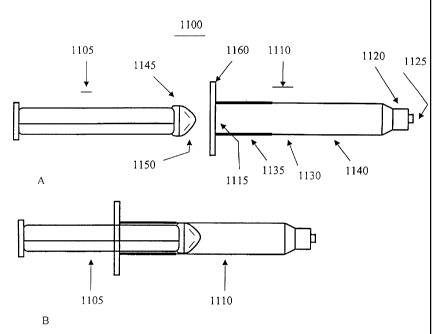
Turning to Figure I 1 A and B, an embodiment of a mixing syringe 1100
according to the
teachings of the subject invention is shown, which allows for the ready mixing
of its
contents. The mixing syringe 1100 comprises a barrel 1110 and a plunger,
wherein the
plunger is inserted into a second end 1115 of the barrel 1110 (see Figure 11
B).
The barrel 1 l 10 comprises a first end 1120 having an opening 1125 for
extruding the mixed
contents of the mixing syringe 1100 to the site of need. As shown, the first
end
CA 02438192 2010-01-18
12
1120 is configured as a luer-lok connector, which would allow engagement to
another luer-
lok connector. In a preferred embodiment, the mixing syringe 1100 is provided
with one or
more paste components and a reconstitution fluid is provided into the mixing
syringe 1100
through the first end 1120, by, for example, connection of a syringe or other
device
containing said reconstitution fluid. However, those skilled in the art will
appreciate that
the first end 1120 can have a number of different connecting means securely
attached or
integral thereto, such as a threaded neck and cap, valve or a septum, which
may or may not
be removable. Between the first end 1120 and second end 1115 of the barrel 1 l
10 is a
midsection 1130 comprising a rigid portion 1135 and a flexible portion 1140.
Preferably, as
shown, the rigid portion 1135 is proximate to said second end 1115, meaning
closer to the
second end 1115 than the first end 1120. When two or more substances are
disposed within
the mixing syringe 1100, and with the plunger situated within the barrel 1110,
the two or
more substances are mixed by squeezing the flexible portion 1140, preferably
repeated
squeezing. The rigid portion 1135, which is part of or proximate to the second
end 1115,
helps maintain the structural integrity of the barrel during mixing. The
mixing syringe 1100
is also provided with a flange 1160 to help manipulate the mixing syringe 1100
during
extrusion of the mixed contents. The flange is preferably made of a rigid
material. To aid in
minimizing the dead space within the barrel 1110 of the mixing syringe 1100,
the insertion
end 1145 of the plunger has a tapered tip 1150.
Naturally, those skilled in the art will appreciated that the insertion end of
the plunger
may take a number of different shapes, such as a flat end, rounded end,
conical, etc.
The flexible portion 1140 should be adequately flexible to be compressible by
hand. Those
skilled in the art will readily appreciate materials suitable for producing
the flexible
portion. Examples of appropriate materials include, but are not limited to,
low density
polymers such as low density polyethylene, silicone, laminate plastics,
polyurethane,
KraytonTM, rubber latex and other suitable flexible elastic materials. If it
is desired to use a
mechanical device for squeezing the flexible portion 1140, the flexibility of
the flexible
portion 1140 may be increased or decreased depending on the desired mode of
squeezing,
with the proviso that some level of flexibility should be maintained. The
rigid portion
CA 02438192 2010-01-18
13
1135 is made from a more rigid material, such as, for example polypropylene.
Other
conventional materials suitable for making the rigid portion will be readily
appreciated by
those skilled in the art. The mixing syringe can be made according to several
conventional
manufacturing techniques, e. g., injection molded, dipping molded, rotational
molded, or
blow molded.
Upon mixing the contents of the mixing syringe 1100, the contents are extruded
out of
the opening 1125 at the first end 1120 to the site of need by applying force
to the plunger.
As mentioned above the first end 1 120 may have a number of different
connectors
securely attached, or integral to the first end 1120, such as, Luer-lok
connector (friction-
fit or screw-type), threaded neck with attachable cap, smooth neck with slip-
fit cap,
septum, one-valve, multiple-way valve. It is preferred that the dimensions of
the opening
are smaller than the dimensions of the inner surface of the barrel 1110,
thereby providing
a smaller end that governs the flow of contents out of the syringe. However,
depending
on the ultimate end-use, the first end 1120 can be cut or pre-scarred such
that the tip of
the first end 1120 is removed, thereby forming a straight-walled open-ended
barrel.
Naturally, the straight-walled open ending is preferred for applications
requiring a high
flow rate of delivery, or where a larger sized mass of mixed contents is
desired, or where
larger bone particles or chips are mixed in the mixing syringe. Furthermore,
the need to
vent air in the mixing syringe is less of an issue because mixing occurs in a
single syringe
and is not being transferred back and forth between syringes. Indeed,
preferably, the
volume of contents in the syringe is such that there is head space between the
level of
contents and the first end to provide room for receiving fluid. More
preferred, the head
space should be about 0-1 inches.
Another embodiment of a mixing syringe is shown in Figures 12 A and B. The
mixing
syringe comprises a barrel 1210 and a plunger 1205. The barrel 1210 comprises
a first
end 1220 and a second end 1215. The midsection 1230 is flexible and the
plunger 1205
comprises a large end 1225, which upon insertion into the barrel 1210 (see
Figure 12B)
acts to stabilize the flexible midsection 1230, and whereby contents within
the
CA 02438192 2003-08-12
WO 02/067814 PCT/US02/05903
14
syringe can be mixed by compression of the midsection 1230 above the position
of the
plunger 1205.
Figure 13A shows a longitudinal cross-section of an optional connector 1300
which is
securely but removably attached to, or integral to, the first end of the
mixing syringes
shown in Figures 11 and 12. The connector 1300 is essentially a one-way valve
that
comprises a body 1305, which is generally cylindrical. The body 1305 comprises
a
channel 1325 formed within. The inner surface of the body defining the channel
has a
tapered portion 1323 which results in a narrowing of the channel 1325. A
stopper 1310 is
positioned in the channel 1325 such that it abuts the inner surface of the
tapered portion
1323. The stopper 1310 is held in place by two flexible bands 1315 that extend
across the
stopper and which are attached to the body 1320. Figure 13B represents a
transverse
cross-section of a connector 1300 along line AA. Figure 13C is a connector
1350 similar
to 1300 except that the body 1307 is shorter in length. Figure 14 shows the
configuration
of Figure 13C engaged to the first end 1353 of a barrel 1355 of a syringe as
disclosed in
Figure 11. Upon engagement of a fluid delivery device to the connector 1300 or
1350,
fluid injected into the mixing syringe pushes the stopper 1310 down which
creates space
between the stopper 1310 and the tapered portion 1323, thereby allowing the
fluid to pass
by and into the barrel 1355. As mixing occurs, contents within the mixing
syringe cannot
escape, as any pressure created causes the stopper 1310 to be pushed up into
the tapered
portion 1323. Optionally, after mixing, the connector 1350 is removed from the
barrel
1355, leaving an opening out of which mixed contents can be extruded.
Example 1
Syringe A is a male Luer-lock. Syringe B is a female Luer-lock having a septum
cap disposed thereon and paste components contained therein.
(1) Attach a 22-30 gauge needle to Syringe A.
(2) Draw up an appropriate amount of reconstitution fluid into syringe A,
preferably blood or plasma.
CA 02438192 2003-08-12
WO 02/067814 PCT/US02/05903
(3) Plunge needle through the septum cap on syringe B and inject the
reconstitution
into syringe B.
(4) Warm Syringe B for 2-6 minutes in 49 degree Celsius water bath.
(5) Remove the septum cap from Syringe B. Remove the needle from syringe A.
5 (6) Attach Syringe A to Syringe B.
(7) Transfer the contents from Syringe A to Syringe B.
(8) Transfer the contents from Syringe B to Syringe A.
(9) Repeat steps (7) and (8) until reconstitution fluid and paste components
are
mixed to form a paste of a desired consistency.
10 (10) Use or rewarm the paste.
Example 2
The inventors have discovered that certain mix of gelatin and DBM sizes which
15 exhibit improved osteogenicity. In a preferred embodiment, the subject
invention is
directed to a mixture of freeze dried DBM and gelatin, where the DBM comprises
certain
size ranges. In this example, the paste composition comprises freeze-dried DBM
particles
having a size of about 125 microns to about 850 microns. Preferably still, the
DBM
particles are about 250 microns to about 500 microns in size, which has
exhibited
enhanced osteogenicity. Furthermore, the gelatin in the paste of this example
is about 125
microns to about 710 microns. Preferably still, the gelatin is about 500 to
about 710
microns in size. In determining the appropriate size ranges, consideration
must be given to
dissolution and percolation balance: smaller particles dissolve better and
larger particles
provide a more balanced percolation.
In an even more preferred embodiment, the paste composition further comprises
and exothermic salt, such as but not limited to, Magnesium sulfate, Magnesium
chloride,
Sodium sulfate, and the like. The addition of the exothermic substance causes
the mixture
to heat upon contact with the reconstitution fluid which aids in the
dissolution of the
gelatin and other components in the paste mixture.
CA 02438192 2007-04-18
16
The paste composition can be stored indefinitely at room temperature and is
osteogenic upon reconstitution.
It should be understood that the examples and embodiments described herein are
for illustrative purposes only and that various modifications or changes in
light thereof will
be suggested to persons skilled in the art and are to be included within the
spirit and
purview of this application and the scope of the appended claims.